

FormNo.3364-930RevA
High-TorqueTrencherHead
CompactUtilityLoaders
ModelNo.22473—SerialNo.310000001andUp
ModelNo.22474—SerialNo.310000001andUp
ToregisteryourproductordownloadanOperator'sManualorPartsCatalogatnocharge,gotowww.T oro.com.OriginalInstructions(EN)
ThisproductcomplieswithallrelevantEuropean
G008933
1
directives,fordetailspleaseseetheseparateproduct
specicDeclarationofConformity(DOC)sheet.
DANGER
Theremaybeburiedpower,gas,and/ortelephone
linesintheworkarea.Shockorexplosionmay
occurifyoudigintothem.
Havethepropertyorworkareamarkedforburied
linesanddonotdiginmarkedareas.Contactyour
localmarkingserviceorutilitycompanytohavethe
propertymarked(forexample,intheUnitedStates,
call811forthenationwidemarkingservice).
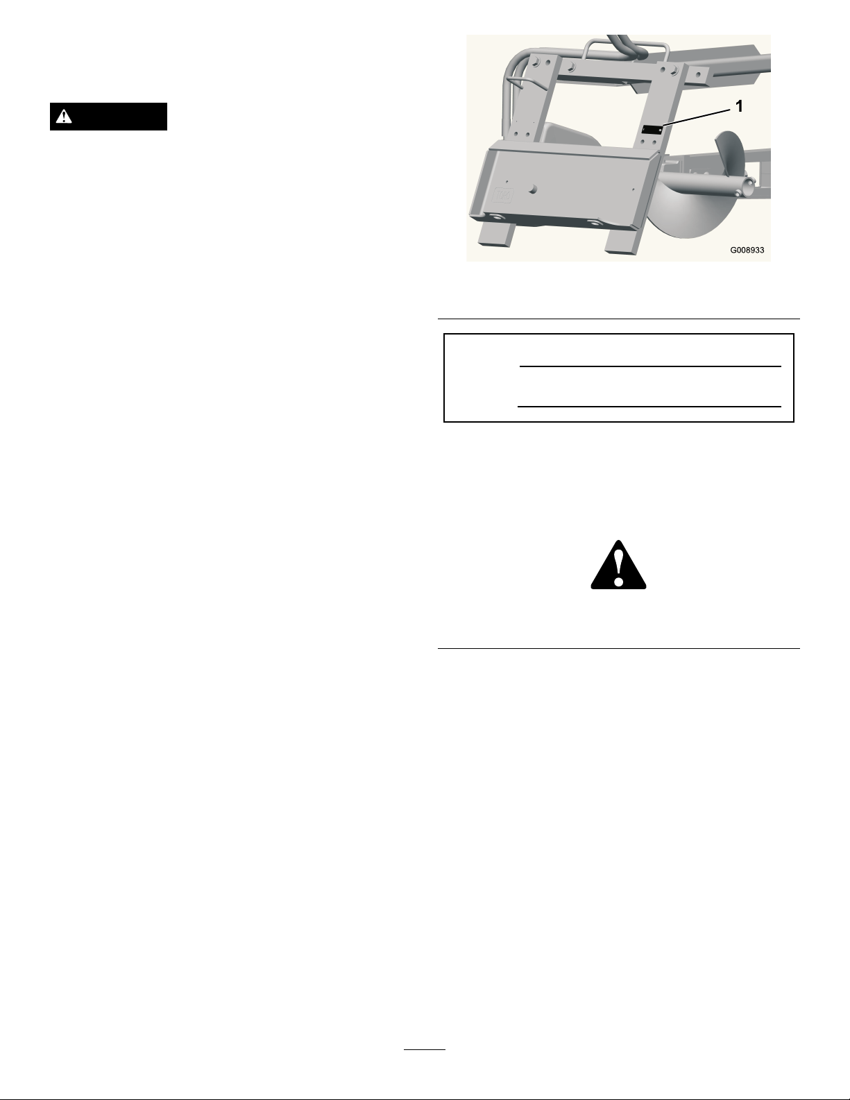
Figure1
1.Modelandserialnumberlocation
Introduction
Thetrencherheadsareattachmentsdesignedforuseon
Torocompactutilityloaderswithavarietyofbooms
andchainstodigtrenchesinsoiltofacilitatetheburying
ofcablingandpiping.Theyarenotintendedforusein
cuttinghardmaterialssuchaswoodorconcrete.
Readthisinformationcarefullytolearnhowtooperate
andmaintainyourproductproperlyandtoavoidinjury
andproductdamage.Youareresponsibleforoperating
theproductproperlyandsafely.
YoumaycontactTorodirectlyatwww .T oro.comfor
productandaccessoryinformation,helpndinga
dealer,ortoregisteryourproduct.
Wheneveryouneedservice,genuineToroparts,or
additionalinformation,contactanAuthorizedService
DealerorToroCustomerServiceandhavethemodel
andserialnumbersofyourproductready .
identiesthelocationofthemodelandserialnumbers
ontheproduct.Writethenumbersinthespace
provided.
Figure1
ModelNo.
SerialNo.
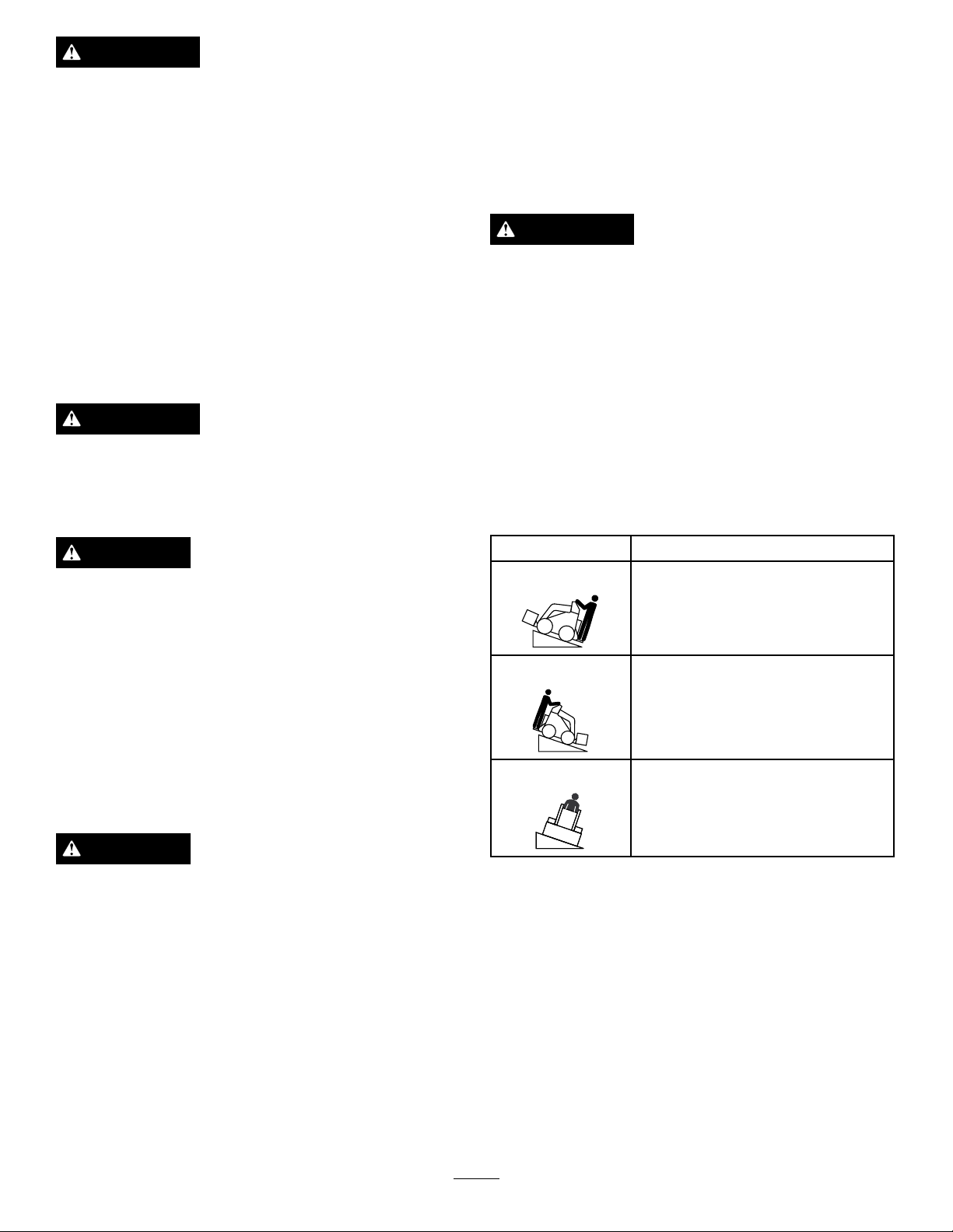
Thismanualidentiespotentialhazardsandhas
safetymessagesidentiedbythesafetyalertsymbol
(Figure2),whichsignalsahazardthatmaycauseserious
injuryordeathifyoudonotfollowtherecommended
precautions.
Figure2
1.Safetyalertsymbol
Thismanualalsouses2wordstohighlightinformation.
Importantcallsattentiontospecialmechanical
informationandNoteemphasizesgeneralinformation
worthyofspecialattention.
©2010—TheT oro®Company
8111LyndaleAvenueSouth
Bloomington,MN55420
Contents
Introduction.................................................................2
Safety...........................................................................3
StabilityRatings....................................................4
SafetyandInstructionalDecals.............................5
Setup............................................................................6
1InstallingtheBoomandDigging
Chain...............................................................6
2InstallingtheSafetyBar......................................6
3InstallingtheSpoilsAuger..................................7
4CheckingtheBearingCaseLubeLevel................7
ProductOverview........................................................8
Contactusatwww.T oro.com.
2
PrintedintheUSA.
AllRightsReserved

Specications.......................................................8
Attachments/Accessories.....................................8
Operation.....................................................................9
DiggingaTrench..................................................9
OffsettingtheTrencher........................................9
TransportingtheTrencheronaTrailer................10
OperatingTips...................................................10
Maintenance...............................................................11
RecommendedMaintenanceSchedule(s)................11
GreasingtheTrencher........................................11
ServicingtheBearingCaseLube.........................11
AdjustingDiggingChainTension.......................12
FlippingaWornBoom.......................................12
ReplacingtheDiggingTeeth...............................13
ReplacingtheDriveSprocket..............................13
Storage.......................................................................14
Troubleshooting.........................................................15
Safety
Improperuseormaintenancebytheoperatoror
ownercanresultininjury.Toreducethepotential
forinjury,complywiththesesafetyinstructionsand
thoseinthetractionunit
payattentiontothesafetyalertsymbol,which
means
safetyinstruction.Failuretocomplywiththe
instructionmayresultinpersonalinjuryordeath.
Caution
,
W ar ning
Operator’ s Man ual
,or
Danger
—personal
DANGER
Theremaybeburiedpower,gas,and/ortelephone
linesintheworkarea.Shockorexplosionmay
occurifyoudigintothem.
Havethepropertyorworkareamarkedforburied
linesanddonotdiginmarkedareas.Contactyour
localmarkingserviceorutilitycompanytohavethe
propertymarked(forexample,intheUnitedStates,
call811forthenationwidemarkingservice).
.Always
DANGER
Themovingteethandaugerwillseverelycuthands,
feet,orotherbodyparts.
•Keephands,feet,andanyotherpartofyour
bodyorclothingawayfrommovingteeth,auger,
orotherparts.
•Beforeadjusting,cleaning,repairing,or
inspectingthetrencher,lowerthetrencherto
theground,stoptheengine,waitforallmoving
partstostop,andremovethekey.
WARNING
Whentheengineisoff,attachmentsintheraised
positioncangraduallylower.Someonenearbymay
bepinnedorinjuredbytheattachmentasitlowers.
Alwayslowertheattachmentlifteachtimeyoushut
offthetractionunit.
WARNING
Whengoingupordownhill,themachinecould
overturniftheheavyendistowardthedownhill
side.Someonemaybepinnedorseriouslyinjured
bythemachineifitoverturns.
Operateupanddownslopeswiththeheavyendof
themachineuphill.Anattachedtrencherwillmake
thefrontendheavy.
3
WARNING
StabilityRatings
Ifyoudonotfullyseattheattachmentlocking
pinsintheattachmentmountplateholes,the
attachmentcouldfalloffofthetractionunitseverely
injuringtheoperatororbystanders.
•Ensurethatyoufullyseattheattachment
lockingpinsthroughtheholesintheattachment
mountplatebeforeliftingtheattachment.
•Ensurethattheattachmentmountplateisfreeof
anydirtordebristhatmayhindertheconnection
ofthetractionunittotheattachment.
•Refertoyourtractionunit
fordetailedinformationonsafelyconnectingan
attachmenttoyourtractionunit.
Operator’ s Man ual
WARNING
Lightningcancausesevereinjuryordeath.If
lightningisseenorthunderisheardinthearea,do
notoperatethemachine;seekshelter.
Todeterminethedegreeofslopeyoucantraversewith
thetrencherinstalledonatractionunit,ndthestability
ratingforthehillpositionyouwanttotravelinthe
appropriatetablebelow,thenndthedegreeofslope
forthesameratingandhillpositionintheStabilityData
sectionofthetractionunitOperator’sManual.
WARNING
Exceedingthemaximumrecommendedslope
cancausethetractionunittotip,crushingyouor
bystanders.
Donotdrivethetractionunitonaslopesteeper
thanthemaximumrecommendedslope,as
determinedinthefollowingtablesandthetraction
Operator’ s Man ual
unit
Important:Ifyouhaveatractionunitotherthana
TXcompactutilityloader,usethecounterweighton
thetractionunitwhenusingthetrencher.Failureto
usethecounterweightwillcausethetractionunitto
becomeunstable.
.
CAUTION
Hydraulicuidescapingunderpressurecan
penetrateskinandcauseinjury.Fluidinjectedinto
theskinmustbesurgicallyremovedwithinafew
hoursbyadoctorfamiliarwiththisformofinjury
organgrenemayresult.
•Keepyourbodyandhandsawayfrompin
holeleaksornozzlesthatejecthighpressure
hydraulicuid.
•Usecardboardorpapertondhydraulicleaks,
neveruseyourhands.
CAUTION
Hydrauliccouplers,hydrauliclines/valves,and
hydraulicuidmaybehotandcanburnyouifyou
touchthem.
•Weargloveswhenoperatingthehydraulic
couplers.
OrientationStabilityRating
FrontUphill
C
RearUphill
D
SideUphill
C
•Allowthetractionunittocoolbeforetouching
hydrauliccomponents.
•Donottouchhydraulicuidspills.
4
SafetyandInstructionalDecals
Safetydecalsandinstructionsareeasilyvisibletotheoperatorandarelocatednearanyareaof
potentialdanger.Replaceanydecalthatisdamagedorlost.
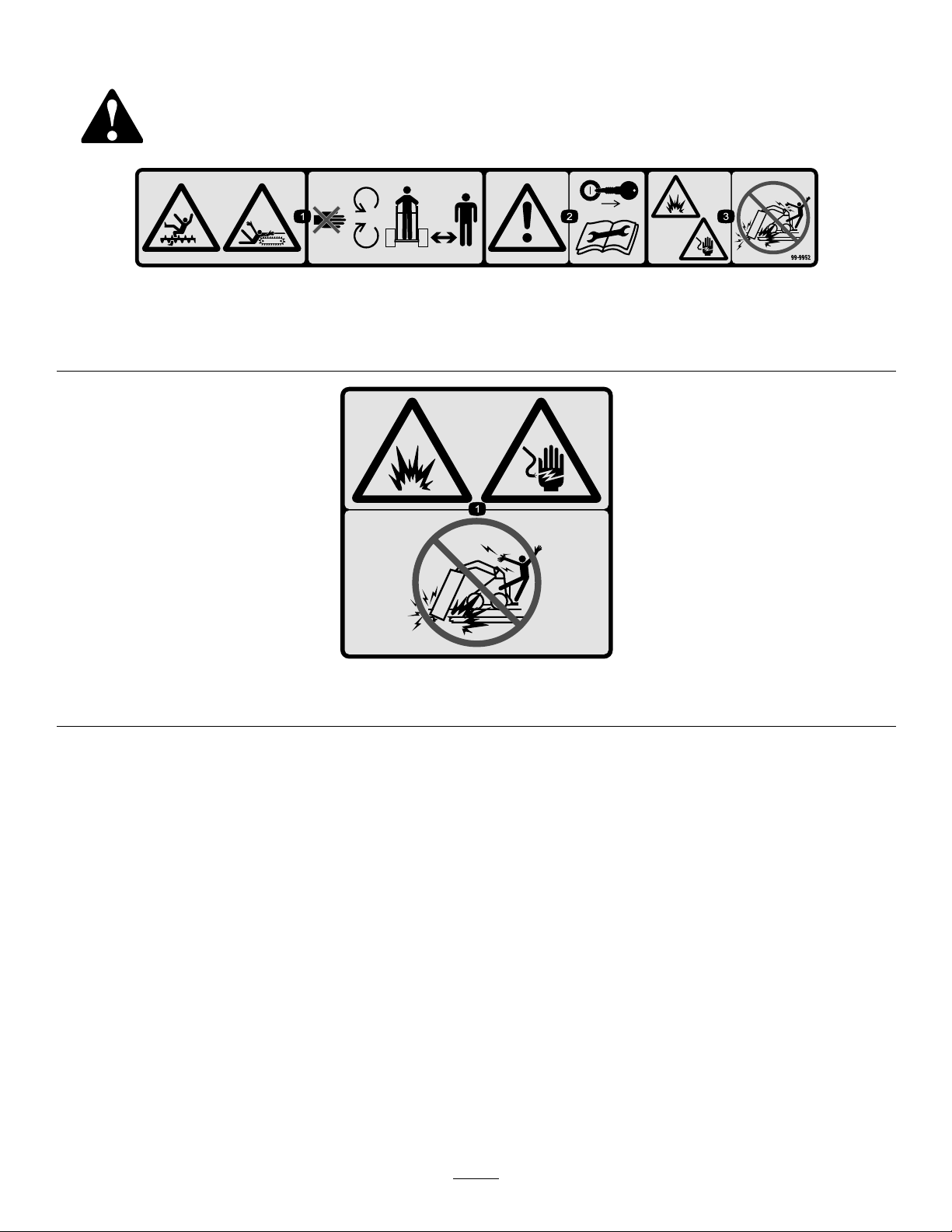
99-9952
1.Cuttinghazard,chainandauger—stayawayfrommovingpartsandkeepbystandersawayfromthemachine.
2.Warning—stoptheengineandremovethekeybeforepreformingandmaintenanceorrepairs.
3.Explosionand/orelectricshockhazard—donotdiginareaswithburiedgasorpowerlines.
99-9953
1.Explosionand/orelectricshockhazard—donotdiginareaswithburiedgasorpowerlines.
5
Setup
G008934
1
2
3
4
5
6
7
8
9
1
7.Installthe2bolts,nuts,anddoublewashersremoved
previouslythroughtheboomandarm,butdonot
tightenthem.
8.Ifthechainisnotconnected,connectthelinksby
pressingorhammeringtheclevispinsuppliedwith
thechainthroughthelinks.
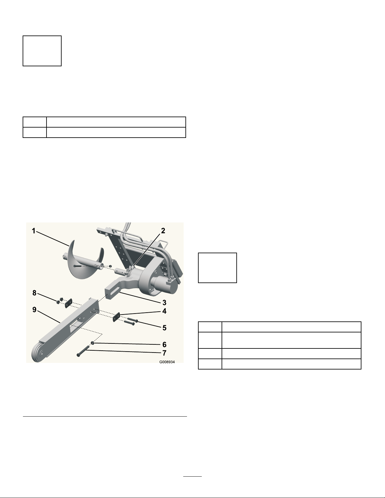
InstallingtheBoomand
DiggingChain
Partsneededforthisprocedure:
1
Boomassembly(soldseparately)
1
Chainassembly(soldseparately)
Procedure
1.Raisethetrencherabout6inches(15cm)offofthe
ground.
2.Stoptheengineandremovethekey.
3.Removetheboltandnutsecuringthespoilsauger
andremovetheauger(
nutforfutureuse.
Figure3).Savetheboltand
Important:T oavoidbendingthechainlinks,
placeblocksunderandbetweenthelinkswhen
hammeringtheclevispinthrough.
9.Securetheclevispinwiththecotterpinsupplied
withthechain.
10.Loopthediggingchainovertheaugerdriveshaftand
ontothedrivesprocket,ensuringthatthedigging
teethpointforwardontheupperspan.
11.Settheupperspanofthechainintoplaceonthe
trencherboom,thenwrapthechainaroundthe
rollerattheendoftheboom.
12.Threadtheadjustmentboltintotheboomandturn
itinuntilthereis1-1/2to2-1/2inches(3.8to6.3
cm)ofslackinthechainonthebottomspan.
13.Threadthejamnutdowntheadjustingboltand
tightenitsecurelyagainsttheboom.
14.Torquethe2boltsandnutssecuringtheboomto
135to165ft-lb(183to223N-m).
1.Spoilsauger
2.Drivesprocket7.Adjustingbolt
3.Armonthedrivehead8.Nuts
4.Doublewasher9.Boom
5.Bolts
4.Removethe2bolts,nuts,anddoublewashersfrom
thesidesoftheboom(Figure3).
5.Loosentheadjustingboltandjamnut(Figure3).
6.Slidetheboomoverthearmonthedrivehead.
Figure3
6.Jamnut
2
InstallingtheSafetyBar
Partsneededforthisprocedure:
1
Safetybar
Safetybarextension(withboomsover2ft(61cm)
1
only)
2
Bolts(withboomsover2ft(61cm)only)
2
Procedure
1.Removethe3bolts,washers,andangenutsfrom
Locknuts(withboomsover2ft(61cm)only)
theupperleftcornerofthetrencherframe(Figure4).
6

123
4
G008935
Figure4
1
2
3
4
5
1.Safetybar
2.Washers4.Flangenuts
2.Usingthefastenersremovedpreviously ,installthe
trenchersafetybarasillustratedinFigure4.
3.Torquetheboltsandnutsto190to230ft-lb(257to
311N-m).
3.Bolts
•6inch(15cm)chainconguration
Usingtheholefarthestfromtheaugerbladein
theendoftheaugerwithtwoholes,connectthe
augertotheinnerholeontheshaft.
•8inch(20cm)chainconguration
Usingtheendoftheaugerwithonehole,
connecttheaugertotheinnerholeontheshaft.
•12inch(25or30cm)chainconguration
Usingtheendoftheaugerwithonehole,
connecttheaugertotheouterholeontheshaft.
4.Ifyouhaveaboomover2ft(61cm),securethe
safetybarextension(suppliedwiththeboom)over
theendofthesafetybarandsecureitusingthe2
boltsandlocknutssuppliedwiththeextension.
3
InstallingtheSpoilsAuger
NoPartsRequired
Procedure
Beforeoperatingthetrencher,installandpositionthe
spoilsaugertoworkcorrectlywiththediggingchain
congurationyouareusing.Failuretopositionthe
spoilsaugercorrectlymaydamagethetrencher.
1.Toinstallandpositiontheauger,usetheboltand
nutremovedfromtheaugerpreviouslytosecureit
inthecorrectholes,asdescribedinthefollowinglist:
Figure5
1.Auger
2.Connecttheseholesfora4inch(10cm)chain
3.Connecttheseholesfora6inch(15cm)chain
4.Connecttheseholesfora8inch(20cm)chain
5.Connecttheseholesfora12inch(30cm)chain
2.Torquetheboltandnutto75ft-lb(101N-m).
Note:RefertoFigure5whenperformingthis
procedure.
•4inch(10cm)chainconguration
Usingtheholeclosesttotheaugerbladeinthe
endoftheaugerwithtwoholes,connectthe
augertotheinnerholeontheshaft.
7
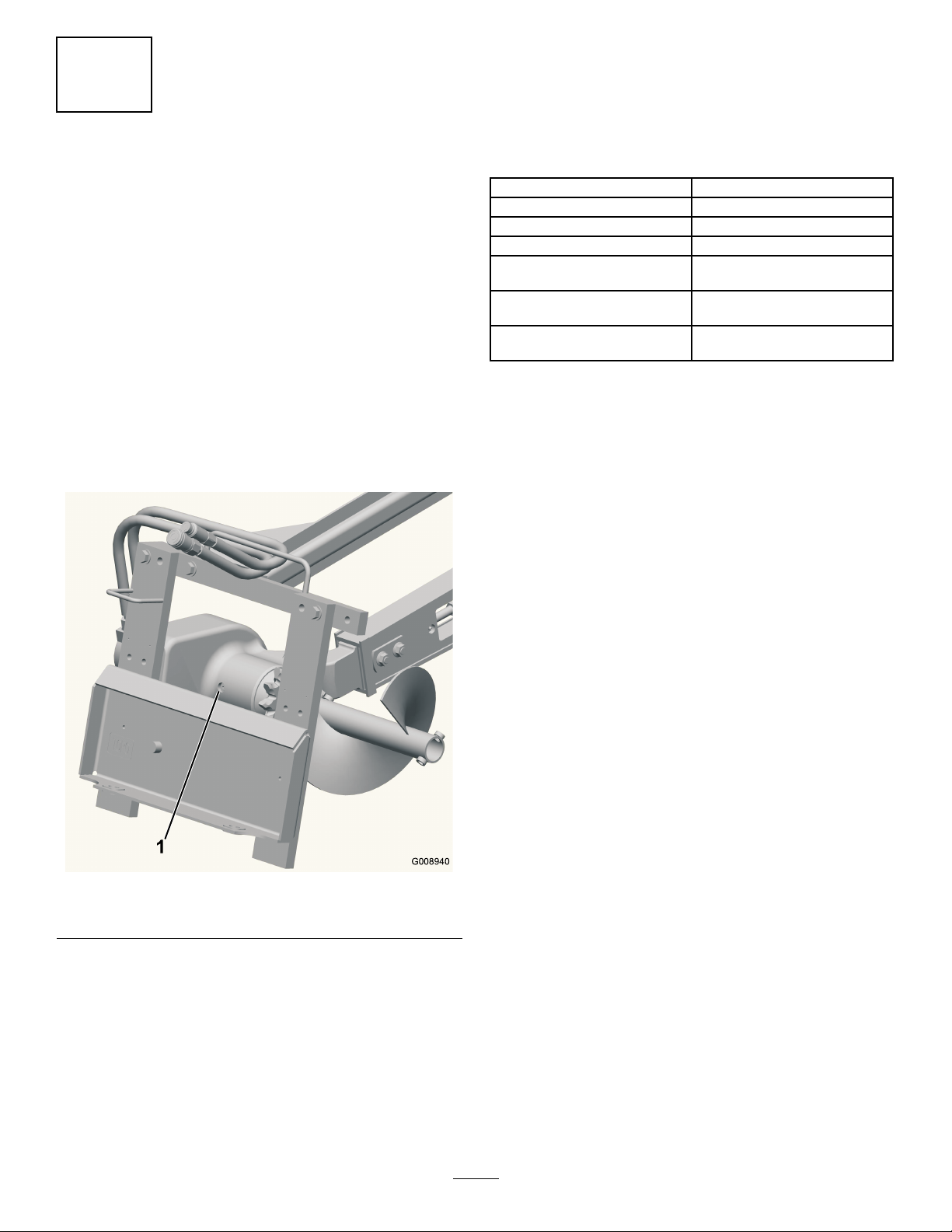
G008940
1
ProductOverview
4
CheckingtheBearingCase
LubeLevel
NoPartsRequired
Procedure
Beforeoperatingthetrencher,checktoensurethatthe
bearingcaseislledwithgearlube.
1.Lowerthetrenchertothegroundonaat,level
surfaceandtiltitsothattheboomisparallelwith
theground.
2.Stoptheengineandremovethekey.
3.Cleantheareaaroundthebearingcasellholeplug
Figure6).
(
Specications
Note:Specicationsanddesignaresubjecttochange
withoutnotice.
Width,with3ft(91cm)boom35inches(89cm)
Length,with3ft(91cm)boom65inches(165cm)
Height,with3ft(91cm)boom24inches(61cm)
Weight,with3ft(91cm)boom390lb(177Kg)
Maximumtrenchdepth,2ft(61
cm)boom
Maximumtrenchdepth,3ft(91
cm)boom
Maximumtrenchdepth,4ft
(122cm)boom
Attachments/Accessories
AselectionofToroapprovedattachmentsand
accessoriesareavailableforusewiththemachineto
enhanceandexpanditscapabilities.Contactyour
AuthorizedServiceDealerorDistributororgoto
www.Toro.comforalistofallapprovedattachments
andaccessories.
24inches(61cm)ata65
degreeboomangle
36inches(91cm)ata65
degreeboomangle
48inches(122cm)ata65
degreeboomangle
Figure6
1.Bearingcasellholeplug
4.Removetheplugfromthebearingcasellhole
(Figure6).
5.Lookinthehole,thelevelshouldbeuptothe
bottomofthehole;ifnotaddgearlubeuntilit
comesoutofthehole.
6.Replacetheplugandtorqueitto15to17ft-lb(20
to23N-m).
8

Operation
G008937
1
2
3
RefertoyourtractionunitOperator’ sManualformore
informationoninstallingandremovingattachments
onyourtractionunit.
Important:Alwaysusethetractionunittoliftand
movetheattachment.
DiggingaTrench
1.Ifyourtractionunithasaspeedselector,setitto
theslow(turtleposition),thenstarttheengine.
WARNING
Hydraulicuidescapingunderpressurecan
penetrateskinandcauseinjury.Fluidinjected
intotheskinmustbesurgicallyremovedwithin
afewhoursbyadoctorfamiliarwiththisform
ofinjuryorgangrenemayresult.
•Keepyourbodyandhandsawayfrompin
holeleaksornozzlesthatejecthighpressure
hydraulicuid.
•Usecardboardorpapertondhydraulic
leaks,neveruseyourhands.
2.Pulltheauxiliaryhydraulicslevertotheoperator
griptoengagethetrencher.
3.Slowlylowerthetrenchertothegroundsothatthe
boomandchainareparalleltotheground.
4.Begininsertingthenoseoftheboomandchain
intothegroundbyslowlyraisingthetrencherafew
inchesoffthegroundwhiletiltingthenosedown
intothegroundgradually.
5.Oncethetrencherboomisinthegroundata45to
60degreeangle,slowlylowerthetrencheruntilthe
spoilsaugerisjustabovetheground.
6.Ensurethatallpartsofthetrencherarefunctioning
correctly.
7.Slowlymovethetractionunitrearwardtoextend
thetrench.
Note:Ifyoumovetoofast,thetrencherwillstall.
Ifitstalls,raiseitslightly ,slowlydriveforward,or
reversethechaindirectionmomentarily .
8.Whennished,raisethetrencherandboomoutof
thetrenchbytiltingtheattachmentrearward,then
stopthetrencherbymovingtheauxiliaryhydraulics
leverintoneutral.
OffsettingtheTrencher
Youcanmovethetrenchertotherightsideofthe
trencherframetoallowyoutotrenchclosetobuildings
andotherobstacles.
2.Removethe6boltssecuringthetrencherheadto
theframe(Figure7).
Figure7
1.Trencherhead(simplied
forillustrativepurposes)
2.Safetybar
3.Movetheframetotheleft,aligningtheholesinthe
rightsideoftheframewiththoseinthehead.
4.Attachtheheadtotheframewiththe6bolts
removedpreviously(
5.Torquetheboltsto190to230ft-lb(257to311
N-m).
6.Removethe3bolts,washers,andangenutsfrom
thesafetybarandremovethebar(
7.Removethe2shortbolts,washers,andangenuts
securingtherightsideoftheupperframeand
movethemtothecorrespondingholesontheleft
(Figure7).
3.Sidehoseguide
Figure7).
Figure7).
1.Lowerthetrenchertotheground,stoptheengine,
anddisconnectthehydrauliclinesfromthetrencher.
8.Installthesafetybaroverthetrencherchainusing
the3bolts,washers,andangenutsremoved
previously(Figure7).
9.Torqueall5boltsandnutsto190to230ft-lb(257
to311N-m).
10.Movethehosesfromthehoseguideontopofthe
9
trenchertothehoseguideontheleftside(Figure7).

TransportingtheTrencheron
aTrailer
Placethetrencheronatrailerortruckcapableof
carryingit.Securelytiethetrenchertothetraileror
truckusingtiestrapsappropriatefortheweightofthe
trencherandforhighwayuse.
OperatingTips
•Cleantheareaoftrash,branchesandrocksbefore
trenchingtopreventequipmentdamage.
•Alwaysbegintrenchingwiththeslowestground
speedpossible.Increasespeedifconditionspermit.
•Alwaysusefullthrottle(maximumenginespeed)
whentrenching.
•Alwaystrenchbackwards(i.e.,inreverse).
•Nevertransportthetrencherwiththeloaderarms
raised.Keepthearmsloweredandthetrencher
tiltedup.
•Whentrenching,thespoilsaugershouldjustclear
theoriginalgroundsurfacetoobtainmaximumsoil
removal.
•Trenchata45to60degreeangleforbestresults.
•Youwillbeabletodigatrenchfasterbycontrolling
thedepthwithperiodicadjustmentsoftheloader
arms.
•Ifyourtractionunithasaspeedselector(present
onsomewheeledtractionunits),setittotheslow
(turtleposition).
•Ifyourtractionunithasaowdivider(present
onsomewheeledtractionunits),adjustitto
approximatelythe10o’clockposition.
•Ifthetrencherbindsinthesoil,pushtheauxiliary
hydraulicsleverfullyforwardtoreversethechain
direction.Oncethechainisloose,pullthelever
rearwardagainandcontinuetrenching.
•Ifyouneedthenishedtrenchtobecleanerthan
whatispossiblewiththetrencher,youcanpurchase
acrumberfromyourdealer.Thecrumbermounts
ontothetrencherandscrapesthetrenchcleanas
yourunthetrencher.
•Toimprovethequalityoftrencheslessthan24
inches(61cm)deep,usea24inch(61cm)boom
onthetrencher.
10
Maintenance
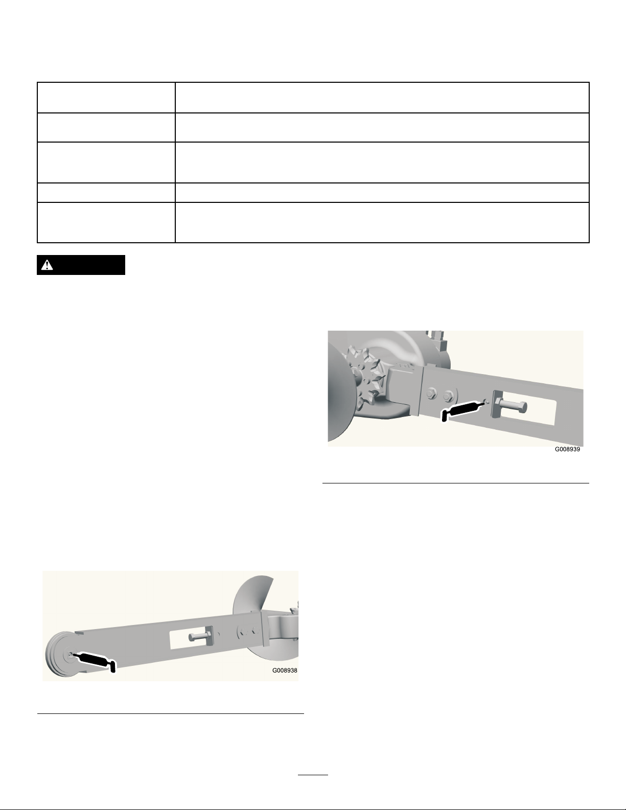
G008938
RecommendedMaintenanceSchedule(s)
MaintenanceService
Interval
Beforeeachuseordaily
Every25hours
Every200hours
Beforestorage
MaintenanceProcedure
•Greasethetrencher.
•Inspectthediggingteethandchainforexcessivewear .
•Checkthegearlubelevel.
•Adjustthediggingchaintension.
•Inspecttheboomforwear.
•Changethegearlube.
•Greasethetrencher.
•Checkthegearlubelevel.
•Paintchippedsurfaces.
CAUTION
Ifyouleavethekeyintheignitionswitch,someonecouldstarttheengine.Accidentalstartingofthe
enginecouldseriouslyinjureyouorotherbystanders.
Removethekeyfromtheignitionswitchbeforeyoudoanymaintenance.
GreasingtheTrencher
ServiceInterval:Beforeeachuseordaily
Beforestorage
Grease2ttings,asshowninFigure8andFigure9,
everydayandimmediatelyaftereverywashing.
GreaseType:General-purposegrease
1.Stoptheengineandremovethekey.
2.Cleanthegreasettingswitharag.
3.Connectagreaseguntoeachtting.
4.Pumpgreaseintothettingsuntilgreasebeginsto
oozeoutofthebearings.
5.Wipeupanyexcessgrease.
Figure8
Figure9
ServicingtheBearingCase
Lube
ServiceInterval:Every25hours
Every200hours
Beforestorage
Gearlubetype:SAE90-140APIserviceGL-4orGL-5
Rellcapacity:1pint(1/2l).
CheckingtheBearingCaseLube
1.Lowerthetrenchertothegroundonaat,level
surfaceandtiltitsothattheboomisparallelwith
theground.
2.Stoptheengineandremovethekey.
3.Cleantheareaaroundthebearingcasellholeplug
(
Figure10).
11

G008940
1
Figure10
1.Bearingcasellholeplug
4.Removetheplugfromthebearingcasellhole
(Figure10).
AdjustingDiggingChain
Tension
ServiceInterval:Every25hours
Withthetrencherparalleltotheground,ensurethat
thereare1-1/2to2-1/2inches(3.8to6.3cm)between
thebottomoftheboomandthetopofthebottom
chainspan.Ifnot,adjustthechainusingthefollowing
procedure:
Important:Donotovertightenthechain.Excess
chaintensionmaydamagedrivecomponents.
1.Loosenthe2boltsandnutssecuringtheboomto
thetrencherarm(
2.Loosenthejamnutsecuringtheadjustmentbolt
Figure3).
(
3.Turntheadjustmentboltinoroutasneededto
achievethedesiredtension.
4.Tightenthejamnut.
5.Torquethe2boltsandnutssecuringtheboomto
135to165ft-lb(183to223N-m).
Figure3).
5.Lookinthehole,thelevelshouldbeuptothe
bottomofthehole;ifnotaddgearlubeuntilit
comesoutofthehole.
6.Replacetheplugandtorqueitto15to17ft-lb(20
to23N-m).
ChangingtheGearLube
1.Cleantheareaaroundthebearingcasellholeplug
(Figure10).
2.Removetheplugfromthebearingcasellhole
(Figure10).
3.Liftthetrencheruntiltheboomisvertical,draining
thelubethroughthellholeandintoapan.
4.Returnthetrenchertotheground.
5.Fillthebearingcasewithgearlubeuntilitcomes
outofthellhole.
6.Replacetheplugandtorqueitto15to17ft-lb(20
to23N-m).
FlippingaWornBoom
ServiceInterval:Every25hours
Inspectthebottomoftheboomforwear,ifitisworn,
completethefollowing:
Note:Ifyouhavealreadyippedtheboomonce,
replacetheboomwhenbothsidesareworn.
1.Removethe2boltsandnutssecuringtheboomto
thetrencherarm(Figure3).
2.Loosenthejamnutontheadjustingboltinthe
boom(
3.Loosentheadjustingboltuntilyoucanremovethe
chainfromtheboom(Figure3).
4.Removethechainfromthedrivesprocket.
5.Removetheboom,ipitoversothebottom
becomesthetop(orifyouhavealreadyippedit
once,replaceit),andinstalltheboomagain.
6.Replacethenuts,bolts,andwasherssecuringthe
boom.
Figure3).
7.Installthechainoverthedrivesprocketandfront
roller.
8.AdjustthechaintensionasdescribedinAdjusting
theDiggingChainTension.
12

ReplacingtheDiggingTeeth
G008941
123
ServiceInterval:Beforeeachuseordaily
Duetothehighamountofwearplacedonthedigging
teeth,youwillneedtoreplacethemperiodically.
Toreplaceasingletooth,removetheboltssecuringthe
toothtoremoveit,theninstallanewtoothinthesame
position.Torquetheboltssecuringtheteethto27to33
ft-lb(37to45N-m).
ReplacingtheDriveSprocket
Overtime,thedrivesprocketwillwear,especiallywhen
usedinsandyorclaysoils.Whenthishappens,the
diggingchainwillbegintoslip.Ifthechainslips,replace
thedrivesprocket,asfollows:
1.Raisethetrencherafewinchesabovetheground.
2.Stoptheengineandremovethekey.
3.Removethespoilsauger(Fig.8).
Important:Thearrowonthesprocketface
shouldbevisiblefromtherightsideofthe
trencherandshouldpointinaclockwise
direction;ifnot,turnthesprocketaround.
12.Threadthe6boltsintothesprocketngertight(Fig.
8).
13.Slowlybegintighteningtheboltsprogressingaround
thesprocketuntilallboltsaretorquedto95to115
ft-lb(129to155N-m).
Important:Tighteneachboltonlyhalfway
rst,workingyourwayaroundthesixbolts,
thenreturntoeachboltinturnandtorquethem
tothespecicationsgiveninstep13.
14.Loopthechainovertheaugerdriveshaftandonto
thedrivesprocket,ensuringthattheteethpoint
forwardontheupperspan.
15.Settheupperspanofthechainintoplaceonthe
trencherboom,thenwrapthechainaroundthe
rollerattheendoftheboom.
16.Threadtheadjustmentboltintotheboomandturn
itinuntilthereis1-1/2to2-1/2inches(3.8to6.3
cm)ofslackinthechainonthebottomspan.
Figure11
1.Spoilsauger
2.Drivesprocket
3.Bolts
4.Loosenthe2boltsandnutssecuringtheboomto
thetrencherarm(Fig.2).
5.Loosenthejamnutontheadjustingboltinthe
boom(Fig.2).
6.Loosentheadjustingboltuntilyoucanremovethe
chainfromtheboom(Fig.2).
7.Removethechainfromthedrivesprocket.
8.Removethe6boltssecuringthedrivesprocket(Fig.
8).
17.Threadthejamnutdowntheadjustingboltand
tightenitsecurelyagainsttheboom.
18.Torquethe2boltsandnutssecuringtheboomto
135to165ft-lb(183to223N-m).
19.Installthespoilsauger;refertoInstallingtheSpoils
Auger.
9.Removeanddiscardthedrivesprocket(Fig.8).
10.Cleanthesprocketmountingsurfaceonthetrencher.
11.Slidethenewsprocketontotheshaftasillustrated
inFigure8.
13

Storage
1.Beforelongtermstorage,brushthedirtfromthe
attachment.
2.Checktheconditionofthediggingchain.Adjustand
lubricatethechain.Replaceanywornordamaged
teeth.
3.Checkandtightenallbolts,nuts,andscrews.Repair
orreplaceanypartthatisdamagedorworn.
4.Ensurethatallhydrauliccouplersareconnected
togethertopreventcontaminationofthehydraulic
system.
5.Paintallscratchedorbaremetalsurfaces.Paintis
availablefromyourAuthorizedServiceDealer.
6.Storethetrencherinaclean,drygarageorstorage
area.Coverthetrenchertoprotectitandkeepit
clean.
14

Troubleshooting
Problem
Thechaindoesnotturn.
Thetrencherdoesnotdigfastenough.
PossibleCauseCorrectiveAction
1.Ahydrauliccouplerisnotcompletely
connected.
2.Ahydrauliccouplerisdamaged.
3.Thereisanobstructioninahydraulic
hose
4.Anauxiliaryvalveonthetractionunit
isnotopening.
5.Theboomendbearingfailed.
6.Thediggingchainistootight.6.Adjustthediggingchain.
7.Thereissandbuildupintoothrootof
thedrivesprocket.
8.Hydraulicmotororchaindrivefailure8.ContactyourAuthorizedService
1.Wornteeth1.Replaceanywornteeth.
2.Wrongsettingonowdividerand
speedlever(applicablewheeledunits
only)
3.Thereisarestrictioninaquickcoupler
orhose.
4.Thehydraulicsystemistoohot.
5.Thereliefvalveissetbelow
specications.
1.Checkandtightenallcouplers.
2.Check/replacecouplers
3.Findandremovetheobstruction.
4.Repairthevalve.
5.Replacethebearing.
7.Raisethetrencherandrunthechain
backwards,thenreducethechain
tension.
Dealer.
2.Settheowdividertothe10:00
positionandthespeedlevertothe
turtleposition.
3.Checkthehosesandcouplersand
repairanyproblemsfound.
4.Shutdownandallowthesystemtocool.
5.ContactyourAuthorizedService
Dealer.
Thechainturnsinthewrongdirection
Thebearingcaselubeiscontaminated.
1.Theauxiliaryvalveleverisinthewrong
position.
2.Thehydraulichosesarereversed.2.Disconnecthosesandswitchpositions.
1.Thellplugisleaking.1.Lookformoisturearoundthellplug.
2.O-ringfailureonthemotor.2.ContactyourAuthorizedService
3.Sealfailure.3.ContactyourAuthorizedService
1.Movetheauxiliaryvalvelevertothe
rearwardposition.
Ifpresent,changetheoil,andreplace
theplugandtheplugo-ring.
Dealer.
Dealer.
15

ToroCompactUtilityEquipmentWarranty
AOne-YearLimitedWarranty
CUEProducts
ConditionsandProductsCovered
TheToro®Companyanditsafliate,T oroWarrantyCompany,pursuant
toanagreementbetweenthem,jointlywarrantyourT oroCompactUtility
Equipment(“Product”)tobefreefromdefectsinmaterialsorworkmanship.
Thefollowingtimeperiodsapplyfromthedateofpurchase:
ProductsWarrantyPeriod
Loaders,TrenchersandAttachments1yearor1000operating
hours,whicheveroccursrst
KohlerEngines3years
AllotherEngines2years
Whereawarrantableconditionexists,wewillrepairtheProductatnocost
toyouincludingdiagnosis,labor,andparts.
InstructionsforObtainingWarrantyService
IfyouthinkthatyourT oroProductcontainsadefectinmaterialsor
workmanship,followthisprocedure:
1.ContactanyAuthorizedT oroCompactUtilityEquipment(CUE)
ServiceDealertoarrangeserviceattheirdealership.T olocatea
dealerconvenienttoyou,accessourwebsiteatwww.T oro.com.
YoumayalsocallourT oroCustomerCareDepartmenttollfree
at888-865-5676(U.S.customers)or888-865-5691(Canadian
customers).
2.Bringtheproductandyourproofofpurchase(salesreceipt)tothe
ServiceDealer.
3.IfforanyreasonyouaredissatisedwiththeServiceDealer’s
analysisorwiththeassistanceprovided,contactusat:
LCBCustomerCareDepartment
ToroW arrantyCompany
811 1LyndaleAvenueSouth
Bloomington,MN55420-1196
TollFree:888-865-5676(U.S.customers)
TollFree:888-865-5691(Canadacustomers)
OwnerResponsibilities
YoumustmaintainyourT oroProductbyfollowingthemaintenance
proceduresdescribedintheOperator’sManual.Suchroutine
maintenance,whetherperformedbyadealerorbyyou,isatyourexpense.
Partsscheduledforreplacementasrequiredmaintenance(“Maintenance
Parts”),arewarrantedfortheperiodoftimeuptothescheduled
replacementtimeforthatpart.Failuretoperformrequiredmaintenance
andadjustmentscanbegroundsfordisallowingawarrantyclaim.
ItemsandConditionsNotCovered
Notallproductfailuresormalfunctionsthatoccurduringthewarranty
periodaredefectsinmaterialsorworkmanship.Thisexpresswarranty
doesnotcoverthefollowing:
•Productfailureswhichresultfromtheuseofnon-Tororeplacement
parts,orfrominstallationanduseofadd-on,modied,orunapproved
accessories
•Productfailureswhichresultfromfailuretoperformrequired
maintenanceand/oradjustments
•ProductfailureswhichresultfromoperatingtheProductinan
abusive,negligentorrecklessmanner
•Partssubjecttoconsumptionthroughuseunlessfoundtobe
defective.Examplesofpartswhichareconsumed,orusedup,during
normalProductoperationinclude,butarenotlimitedto,diggingteeth,
tines,sparkplugs,tires,tracks,lters,chains,etc.
•Failurescausedbyoutsideinuence.Itemsconsideredtobeoutside
inuenceinclude,butarenotlimitedto,weather,storagepractices,
contamination,useofunapprovedcoolants,lubricants,additives,or
chemicals,etc.
•Normal“wearandtear”items.Normal“wearandtear”includes,butis
notlimitedto,wornpaintedsurfaces,scratcheddecalsorwindows,
etc.
•Anycomponentcoveredbyaseparatemanufacturer’swarranty
•Pickupanddeliverycharges
GeneralConditions
RepairbyanAuthorizedT oroCompactUtilityEquipment(CUE)Service
Dealerisyoursoleremedyunderthiswarranty.
NeitherTheToro®CompanynorToroWarrantyCompanyisliable
forindirect,incidentalorconsequentialdamagesinconnectionwith
theuseoftheToroProductscoveredbythiswarranty,including
anycostorexpenseofprovidingsubstituteequipmentorservice
duringreasonableperiodsofmalfunctionornon-usepending
completionofrepairsunderthiswarranty.Allimpliedwarranties
ofmerchantabilityandtnessforusearelimitedtotheduration
ofthisexpresswarranty .Somestatesdonotallowexclusionsof
incidentalorconsequentialdamages,orlimitationsonhowlong
animpliedwarrantylasts,sotheaboveexclusionsandlimitations
maynotapplytoyou.
Thiswarrantygivesyouspeciclegalrights,andyoumayalsohaveother
rightswhichvaryfromstatetostate.
ExceptfortheenginewarrantycoverageandtheEmissionswarranty
referencedbelow,ifapplicable,thereisnootherexpresswarranty.The
EmissionsControlSystemonyourProductmaybecoveredbyaseparate
warrantymeetingrequirementsestablishedbytheU.S.Environmental
ProtectionAgency(EPA)ortheCaliforniaAirResourcesBoard(CARB).
ThehourlimitationssetforthabovedonotapplytotheEmissions
ControlSystemWarranty .RefertotheCaliforniaEmissionControl
WarrantyStatementsuppliedwithyourProductorcontainedintheengine
manufacturer’sdocumentationfordetails.
CountriesOtherthantheUnitedStatesorCanada
CustomerswhohavepurchasedT oroproductsexportedfromtheUnitedStatesorCanadashouldcontacttheirT oroDistributor(Dealer)toobtain
guaranteepoliciesforyourcountry ,province,orstate.IfforanyreasonyouaredissatisedwithyourDistributor’sserviceorhavedifcultyobtaining
guaranteeinformation,contacttheToroimporter.Ifallotherremediesfail,youmaycontactusatT oroWarrantyCompany .
374-0261RevA
 Loading...