

Page 1
Snowthrower
Sitework Systems Attachment
Model No. 22456—990001 & Up
Form No. 3321-607
Operator ’s Manual
English (CE)
Page 2

Contents
Introduction 2. . . . . . . . . . . . . . . . . . . . . . . . . . . . . . . .
Safety 2. . . . . . . . . . . . . . . . . . . . . . . . . . . . . . . . . . . . .
General Snowthrower Safety 3. . . . . . . . . . . . . . . .
Toro Snowthrower Safety 4. . . . . . . . . . . . . . . . . .
Safety Decals 5. . . . . . . . . . . . . . . . . . . . . . . . . . . .
Specifications 5. . . . . . . . . . . . . . . . . . . . . . . . . . . . . . .
Stability Ratings 6. . . . . . . . . . . . . . . . . . . . . . . . . .
Installation 6. . . . . . . . . . . . . . . . . . . . . . . . . . . . . . . . .
Loose Parts 6. . . . . . . . . . . . . . . . . . . . . . . . . . . . . .
Installing the Discharge Chute 7. . . . . . . . . . . . . . .
Installing the Cable Guide 7. . . . . . . . . . . . . . . . . .
Installing the Snowthrower on the Traction Unit 7
Removing the Snowthrower from the
Traction Unit 7. . . . . . . . . . . . . . . . . . . . . . . . . . .
Side Plate Template for Marking the
Hole Location 8. . . . . . . . . . . . . . . . . . . . . . . . . .
Operation 9. . . . . . . . . . . . . . . . . . . . . . . . . . . . . . . . . .
Tips for Throwing Snow 9. . . . . . . . . . . . . . . . . . .
Maintenance 10. . . . . . . . . . . . . . . . . . . . . . . . . . . . . . . .
Service Interval Chart 10. . . . . . . . . . . . . . . . . . . . .
Checking the Auger Gear Box Oil 10. . . . . . . . . . . .
Checking/Adjusting the Discharge Chute 10. . . . . .
Adjusting the Skids 11. . . . . . . . . . . . . . . . . . . . . . .
Replacing the Scraper Blade 11. . . . . . . . . . . . . . . .
Storage 11. . . . . . . . . . . . . . . . . . . . . . . . . . . . . . . . .
Troubleshooting 12. . . . . . . . . . . . . . . . . . . . . . . . . . . . .
Page
The warning system in this manual identifies potential
hazards and has special safety messages that help you and
others avoid personal injury, even death. DANGER,
WARNING and CAUTION are signal words used to
identify the level of hazard. However, regardless of the
hazard, be extremely careful.
DANGER signals an extreme hazard that will cause
serious injury or death if the recommended precautions
are not followed.
WARNING signals a hazard that may cause serious injury
or death if the recommended precautions are not followed.
CAUTION signals a hazard that may cause minor or
moderate injury if the recommended precautions are not
followed.
Two other words are also used to highlight information.
“Important” calls attention to special mechanical
information and “Note” emphasizes general information
worthy of special attention.
The left and right side of the machine is determined by
standing in the normal operator’s position.
Safety
Improper use or maintenance by the operator or owner
can result in injury. To reduce the potential for injury,
comply with the safety instructions in the traction unit
operator ’s manual and always pay attention to the
safety alert symbol, which means CAUTION,
WARNING, or DANGER—“personal safety
instruction.” Failure to comply with the instruction
may result in personal injury or death.
Introduction
We want you to be completely satisfied with your new
product, so feel free to contact your local Authorized
Service Dealer for help with service, genuine replacement
parts, or other information you may require.
Whenever you contact your Authorized Service Dealer or
the factory, always know the model and serial numbers of
your product. These numbers will help the Service Dealer
or Service Representative provide exact information about
your specific product. You will find the model and serial
number on a plate located on the product.
Model No:
Serial No.
The Toro Company – 1999
8111 Lyndale Ave. South
Bloomington, MN 55420–1196
2
All Rights Reserved
Printed in the USA
Page 3
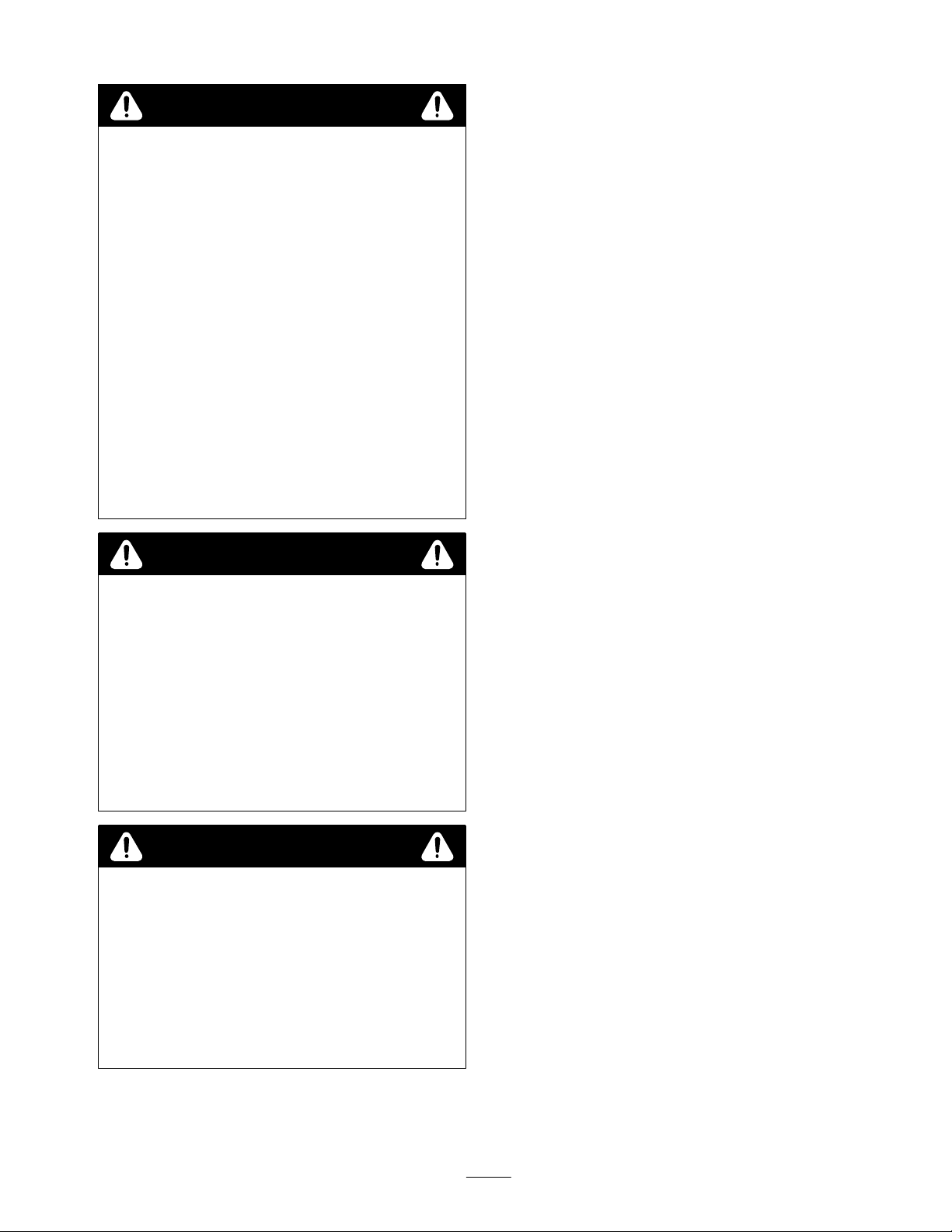
DANGER
POTENTIAL HAZARD
• The rotating impeller/auger can cut off fingers,
hands, or other body parts.
WHAT CAN HAPPEN
• Contact with the rotating impeller/auger can
cause severe injury or death.
HOW TO AVOID THE HAZARD
• Stay away from the discharge and auger
openings while operating the snowthrower.
• Keep your hands, feet, and any other part of
your body or clothing away from concealed,
moving, or rotating parts.
• Use a stick, not your hand, to remove
obstructions from the discharge chute or auger
housing.
• Before adjusting, cleaning, repairing, and
inspecting the snowthrower and before
unclogging the discharge chute, stop the engine
and wait for all moving parts to stop. Remove
the key.
WARNING
General Snowthrower Safety
The following instructions have been adapted from the
ANSI/OPEI and ISO standards.
Preparation
• Thoroughly inspect the area where the equipment is to
be used and remove all doormats, sleds, boards, wires,
and other foreign objects.
• Do not operate the equipment without wearing
adequate winter outer garments. Wear footwear that
will improve footing on slippery surfaces.
• Adjust the auger housing height to clear gravel or
crushed rock surface.
• Never attempt to make any adjustments while the
engine is running, except when specifically
recommended by Toro.
• Let engine and machine adjust to outdoor temperatures
before starting to clear snow.
• The operation of any powered machine can result in
foreign objects being thrown into the eyes. Always
wear safety glasses or eye shields during operation or
while performing an adjustment or repair.
POTENTIAL HAZARD
• Stones and other foreign objects may be picked
up and thrown by the rotor blades.
WHAT CAN HAPPEN
• Thrown objects can cause serious personal
injury to operator or bystanders.
HOW TO AVOID THE HAZARD
• Keep the work area free of all objects that
could be thrown by the rotor blades.
• Keep all children and pets away from area of
operation.
WARNING
POTENTIAL HAZARD
• When the engine is off, attachments in the
raised position can gradually lower.
WHAT CAN HAPPEN
• Someone nearby may be pinned or injured by
the attachment as it lowers.
HOW TO AVOID THE HAZARD
• Always lower the attachment lift each time you
shut off the traction unit.
Operation
• Do not put hands or feet near or under rotating parts.
Keep clear of the discharge opening at all times.
• Exercise extreme caution when operating on or
crossing gravel drives, walks, or roads. Stay alert for
hidden hazards or traffic. Do not carry passengers.
• After striking a foreign object, stop the engine, cycle
the auxiliary hydraulics lever, disconnect the hydraulic
lines, thoroughly inspect the snowthrower for any
damage, and repair the damage before restarting and
operating the snowthrower.
• If the unit should start to vibrate abnormally, stop the
engine and check immediately for the cause. Vibration
is generally a warning of trouble.
• Stop the engine whenever you leave the operating
position, before unclogging the auger/impeller housing
or discharge chute, and when making any repairs,
adjustments, or inspections.
• When cleaning, repairing, or inspecting, stop the
engine, make certain the auger/impeller and all
moving parts have stopped, cycle the auxiliary
hydraulics lever, and disconnect the hydraulic lines.
• Do not clear snow across the face of slopes. Exercise
extreme caution when changing direction on slopes.
Do not attempt to clear steep slopes.
3
Page 4

• Never operate the snowthrower without proper guards,
plates, or other safety protective devices in place.
• Never operate the snowthrower near glass enclosures,
automobiles, window wells, drop-offs, and the like
without proper adjustment of the snow discharge
angle. Keep children and pets away.
• Do not overload the machine capacity by attempting to
clear snow at too fast a rate.
• Never operate the machine at high transport speeds on
slippery surfaces. Look behind and use care when
moving in reverse.
• Never direct discharge at bystanders or allow anyone
in front of the unit.
• Disengage power to the auger/impeller when the
snowthrower is transported or not in use.
• Never operate the snowthrower without good visibility
or light.
operating the snowthrower. Keep your face hands,
feet, and any other part of your body or clothing
away from concealed, moving, or rotating parts.
• Before adjusting, cleaning, repairing, and inspecting
the snowthrower, and before unclogging the discharge
chute, stop the engine, remove the key, and wait for
all moving parts to stop. Also, cycle the auxiliary
hydraulics lever and disconnect the hydraulic lines.
• Use a stick, not your hands to remove obstructions
from the discharge chute.
• Before leaving the operator ’s position, stop the engine,
remove the key, and wait for all moving parts to stop.
• Do not wear loose fitting clothing that could possibly
get caught in moving parts.
• If a shield, safely device, or decal is damaged,
illegible, or lost, repair or replace it before beginning
operation. Also, tighten any loose fasteners.
• Do not use the snowthrower on a roof.
Maintenance and Storage
• Check fasteners at frequent intervals for proper
tightness to be sure the equipment is in safe working
condition.
• Always refer to the operator’s manual for important
details if the snowthrower is to be stored for an
extended period.
• Maintain or replace safety and instruction labels, as
necessary.
• Run the machine a few minutes after throwing snow to
prevent freeze-up of the auger/impeller.
Toro Snowthrower Safety
The following list contains safety information specific to
Toro products or other safety information that you must
know that is not included in the ANSI or ISO standards.
• The rotating auger/impeller or rotor blades can cut
off or injure fingers or hands. Stay in the operator’s
position and away from the discharge opening while
• Perform only those maintenance instructions described
in this manual. Before performing any maintenance,
service, or adjustment, stop the engine, remove the
key, cycle the auxiliary hydraulics lever, and
disconnect the hydraulic lines. If major repairs are
ever needed, contact your Authorized Toro Service
Dealer.
• To ensure the best performance and safety, purchase
only genuine Toro replacement parts and accessories
to keep the Toro all Toro. Do not use “Will Fit”
replacement parts and accessories as they could
cause a safety hazard.
• When using the snowthrower in a raised position, stay
away from overhead power lines and drive the traction
unit only on level surfaces.
• Always transport the snowthrower in a lowered
position.
• Use the snowthrower only to remove snow. Other
materials may damage the snowthrower and cause a
hazard.
• Do not tilt the snowthrower so that it discharges
towards the operator or bystanders.
4
Page 5

Safety Decals
4
1
4
6
9
# 93–7310
3
5
2
7
6
8
# 93–7311
Figure 1
1. Cutting hazard—rotating
auger
2. Keep bystanders away
3. Do not place hands or feet
into areas with moving parts
4. Cutting hazard—rotating
impeller
5. Thrown object hazard
6. Safety alert symbol
7. Remove the key and read
the operator’s manual before
servicing
Specifications
Note: Specifications and design are subject to change without notice.
Width 47.75 inches (121.3 cm)
Length 43.2 inches (109.7 cm)
# 63–3510
3
# 93–7309
8. Read the operator’s manual
9. Discharge chute rotation
Height 50.4 inches (128 cm)
Weight 335 lbs (152 Kg)
Clearing width 44 inches (111.7 cm)
Auger diameter 16 inches (40.6 cm)
Impeller diameter 13.5 inches (34.3 cm)
Auger speed 125 rpm @ 8.5 gpm
Impeller speed 1125 rpm @ 8.5 gpm
Hydraulic motor displacement 1.58 cu. in. (25.9 cc)
5
Page 6

Stability Ratings
To determine the degree of slope you can traverse with the
snowthrower installed on a traction unit, find the stability
rating for the hill position you want to travel in the table
below, then find the degree of slope for the same rating
and hill position in the Stability Data section of the
traction unit operator’s manual.
Note: On traction units with a rear operator platform, the
snowthrower is rated for use without the counterweight. If
you use the counterweight with the snowthrower, the
traction unit will be less stable in the front and side uphill
positions.
WARNING
Orientation Stability Rating
Front Uphill
C
Rear Uphill
C
Side Uphill
B
Installation
Loose Parts
Description Qty Use
POTENTIAL HAZARD
• Exceeding the maximum recommended slope
can cause the traction unit to tip.
WHAT CAN HAPPEN
• If the traction unit tips, you or bystanders could
be crushed.
HOW TO AVOID THE HAZARD
• Do not drive the traction unit on a slope steeper
than the maximum recommended slope, as
determined in the previous table and the
traction unit operator’s manual.
Snowthrower housing
Discharge chute assembly
Deflector shield
Carriage bolt
Washer
Lock nut
Cable guide 1 Install on the loader arm crossbar to guide the
Snowthrower 1 Install the snowthrower on the traction unit
Chute control bracket
Knob
Handle clamp
Washer, large
Washer, small
1
1
1
Install the discharge chute
3
3
3
control cable.
1
2
Install the chute control bracket on the traction
1
unit
1
1
6
Page 7

Installing the Discharge Chute
Install the deflector shield and the discharge chute
assembly onto the snowthrower housing with three
carriage bolts (heads to inside), washers, and lock nuts
(Fig. 2).
1
2
3
4
5
m–4543
Figure 2
1. Discharge chute
2. Carriage bolt
3. Washer
4. Lock nut
5. Deflector shield
Installing the Cable Guide
2. Locate the hole in the side plate of the frame (Fig. 4)
that is located just behind and to the left of the left
handle. If there is no hole, complete the following:
A. Copy page 8, cut out the template, and align it
with the upper left side plate of the traction unit
(the arrow on the template should point up).
Note: The template is designed to fit on the outside of the
side plate.
B. Mark the hole location on the side plate at the
center of the cross hairs on the template.
C. Drill a 3/8 to 1/2 inch (1 to 1.25 cm) hole through
the frame at the marked location.
3. Place the chute control bracket between the left handle
and the side plate (Fig. 4).
4. Secure the bracket to the frame with a knob and the
large washer (Fig. 4).
5. Insert the handle clamp into the slot in the chute
control bracket, wrapping it around the handle, then
secure it with a knob (Fig. 4).
1. If your traction unit has a bolt installed in the
underside of the loader arm cross bar, between the
right loader arm and the hydraulic hoses, remove the
bolt.
2. Place the cable guide over the loader arm cross bar on
the far right side (Fig. 3).
3. Insert the clamp into the slot in the cable guide, then
secure it with a knob (Fig. 3).
1
2
5
4
3
m–4545
Figure 3
1. Cable guide
2. Loader arm cross bar
3. Clamp
4. Slot
5. Knob
Installing the Snowthrower on
the Traction Unit
1. Connect the snowthrower to the traction unit mount
plate and connect the hydraulic lines. Refer to your
traction unit operator ’s manual for instructions.
m–4158
Figure 4
1. Chute control bracket
2. Upper left side plate
3. Knob
4. Left handle
5. Large washer
6. Handle clamp
6. Route the chute control cable through the cable guide.
Removing the Snowthrower
from the Traction Unit
1. Start the engine and lower the attachment to the
ground or onto a trailer, then stop the engine.
2. Remove the knobs, washer, and handle clamp from the
chute control bracket and remove the bracket.
3. Install the handle clamp, washer, and knobs on the
chute control bracket for safe keeping.
4. Remove the chute control cable from the cable guide.
5. Disconnect the hydraulic lines and remove the
snowthrower from the mount plate. Refer to your
traction unit operator ’s manual for instructions.
7
Page 8

Side Plate Template for Marking the Hole Location
This page may be copied for installation purposes.
8
Page 9

Operation
DANGER
POTENTIAL HAZARD
• The rotating impeller/auger can cut off fingers,
hands, or other body parts.
WHAT CAN HAPPEN
• Contact with the rotating impeller/auger can
cause severe injury or death.
HOW TO AVOID THE HAZARD
• Stay away from the discharge and auger
openings while operating the snowthrower.
• Keep your hands, feet, and any other part of
your body or clothing away from concealed,
moving, or rotating parts.
• Use a stick, not your hand, to remove
obstructions from the discharge chute or auger
housing.
• Before adjusting, cleaning, repairing, and
inspecting the snowthrower and before
unclogging the discharge chute, stop the engine
and wait for all moving parts to stop. Remove
the key.
Note: Always use the traction unit to lift and move the
attachment.
2
1
1290a
Figure 5
1. Discharge chute 2. Chute deflector
• Remove snow as soon as possible after it falls. This
produces the best snow removal results.
• Adjust the skids to match the type of surface being
cleaned; refer to Adjusting Skids.
• The snowthrower is designed to clean snow down to
the contact surface, but there are times when the front
of the snowthrower may tend to ride up. If this
happens, reduce forward speed.
• Discharge snow downwind whenever possible, and
overlap each pass to ensure complete snow removal. If
wheels slip, reduce forward speed.
Tips for Throwing Snow
• Always use full throttle (maximum engine speed).
• If your traction unit has a speed selector, use the slow
position (turtle).
• If your traction unit has a flow divider, set it as
appropriate for the snow conditions (i.e., vary the
setting from 10 o’clock for heavy snow to 12 o’clock
for lighter snow).
• The discharge chute can be rotated 180° side to side.
The direction is controlled by turning the chute control
crank in the chute control bracket.
• The chute deflector, on top of the discharge chute, can
be moved up and down to control the height and
distance snow is thrown (Fig. 5).
• Run the snowthrower for a few minutes after clearing
snow so moving parts do not freeze.
• Do not overload the snowthrower by clearing snow at
too fast a rate. If the engine slows down, reduce
forward speed or adjust the flow divider (where
applicable) to supply more power to the snowthrower.
• In some snow and cold weather conditions, some
controls and moving parts may freeze. Therefore,
when any control becomes hard to operate, stop the
machine and wait for all moving parts to stop; then
check all parts for freeze up. Do not use excessive
force when trying to operate frozen controls. Free
all controls and moving parts before operating.
9
Page 10

Maintenance
Service Interval Chart
Initial
Service Operation
Auger gearbox–check oil X X
Discharge chute–check and adjust X X
Skids–adjust as required X X
Scraper blade–check\replace X X
Use25Hours50Hours
100
Hours
200
Hours
CAUTION
POTENTIAL HAZARD
• If you leave the key in the ignition switch, someone could start the engine.
WHAT CAN HAPPEN
• Accidental starting of the engine could seriously injure you or other bystanders.
HOW TO AVOID THE HAZARD
• Remove the key from the ignition switch and pull the wire(s) off the spark plug(s) before you
do any maintenance. Also push the wire(s) aside so it does not accidentally contact the spark
plug(s).
Checking the Auger Gear Box
Checking/Adjusting the
Storage
Service
Oil
Check level of oil in auger gear box every 50 hours.
1. With the snowthrower lowered and on a level surface,
remove the pipe plug from the auger gear box (Fig. 6)
by placing the open end of a 3/8” drive socket
extension over the plug and using a 3/8” open end
wrench on the square end of the extension.
2. Check the level of oil in the gear box. The oil must be
at the point of overflowing in the filler opening.
3. If the oil level is low, add SAE 90 EP GL-4
transmission oil to the gear box.
4. Install the pipe plug in the gear box.
m–2362
Figure 6
1. Pipe plug
Discharge Chute
Check the operation of the discharge chute every 25 hours
to ensure that the chute rotates smoothly when the chute
control crank is turned. If it does not rotate smoothly,
adjust the worm gear as follows:
1. Loosen the worm bracket mounting screws (Fig. 7),
firmly pushing the worm gear against the teeth in the
retaining ring.
Figure 7
1. Worm bracket 2. Worm gear
m–2359
10
Page 11

2. While holding the bracket in place, tighten the
mounting screws.
Adjusting the Skids
The distance between the scraper blade and the ground is
controlled by skids on each side of the housing. The
height can be adjusted so the scraper blade will not catch
on uneven surfaces
1. Lower the snowthrower until it is 1 to 2 inches above a
level surface, then stop the engine.
2. Remove the nuts and bolts securing the skids to the
housing (Fig. 8).
3. Position the skids equally on both sides, to obtain a
level scraping action, and secure the skids with the
nuts and bolts (Fig. 8).
Note: On smooth, paved surfaces, the scraper blade can be
close to the surface On uneven, gravel or crushed rock
surfaces, adjust the skids to raise the scraper, to prevent
catching or picking up rocks.
1. Raise the snowthrower a foot off of the ground and
stop the engine.
2. Remove the nuts, washers, carriage bolts, and scraper
blade (Fig. 9).
3. Replace the scraper blade and secure the new blade
with the previously removed hardware (Fig. 9).
3
2
1
4
m–1281
Figure 9
1. Nut
2. Washer
3. Carriage bolt
4. Scraper blade
m–2822
Figure 8
1. Skid
2. Housing
3. Nut
IMPORTANT: The scraper should be higher above the
pavement if the pavement surfaces on which the
snowthrower will be used are cracked, rough, or
uneven.
Replacing the Scraper Blade
Storage
1. Before long term storage, wash the snowthrower with
mild detergent and water to remove dirt and grime.
2. Check the condition of the scraper blade; refer to
Replacing Scraper Blade, page 11.
3. Check the auger gear box oil level; refer to Checking
the Auger Gear Box Oil.
4. Check and tighten all bolts, nuts, and screws. Repair or
replace any part that is damaged or defective.
5. Paint all scratched or bare metal surfaces. Paint is
available from your Authorized Service Dealer.
6. Store the snowthrower in a clean, dry garage or storage
area. Cover the snowthrower to protect it and keep it
clean.
The scraper blade contacts the ground preventing damage
to the snowthrower housing. Periodically inspect the
scraper blade for wear. When the scraper becomes worn,
before the working surface contacts the housing, replace
the scraper blade.
11
Page 12

Troubleshooting
PROBLEM POSSIBLE CAUSES CORRECTIVE ACTION
Snowthrower does not operate.
1. Hydraulic coupler not
completely connected
2. Damaged hydraulic coupler 2. Check couplers and replace
3. An obstruction in a hydraulic
hose
4. Auxiliary valve on the traction
unit is not opening.
1. Check and tighten all couplers.
any that are damaged.
3. Find and remove the
obstruction.
4. Repair the valve.
12
 Loading...