

Page 1
Tiller
Sitework Systems Attachment
Model No. 22445 – 890001 & Up
FORM NO. 3322–129
Operator’s Manual
English (CE)
Page 2
Contents
Page
Introduction 2.
Safety 2
Safety Decals3. . . . . . . . . . . . . . . . . . . . . . . . . . . . .
Specifications 3
Stability Ratings4. . . . . . . . . . . . . . . . . . . . . . . . . . .
Installation 4
Installing the T
Connecting the Hydraulic Hoses4. . . . . . . . . . . . . .
Removing the T
Operation 5
T
ips for T
Maintenance 6
Service Interval Chart6. . . . . . . . . . . . . . . . . . . . . .
Greasing and Lubrication6. . . . . . . . . . . . . . . . . . . .
Adjusting T
T
iller T
Storage 7
Troubleshooting 8
. . . . . . . . . . . . . . . . . . . . . . . . . . . . . . . .
. . . . . . . . . . . . . . . . . . . . . . . . . . . . . . . . . . . . . .
. . . . . . . . . . . . . . . . . . . . . . . . . . . . . . . .
. . . . . . . . . . . . . . . . . . . . . . . . . . . . . . . . . .
iller on the T
iller from the T
. . . . . . . . . . . . . . . . . . . . . . . . . . . . . . . . . . .
illing 5
. . . . . . . . . . . . . . . . . . . . . . . . . . . .
. . . . . . . . . . . . . . . . . . . . . . . . . . . . . . . . .
iller Drive Chain T
ine Replacement7. . . . . . . . . . . . . . . . . . . . .
. . . . . . . . . . . . . . . . . . . . . . . . . . . . . . . . . .
. . . . . . . . . . . . . . . . . . . . . . . . . . . . . .
raction Unit4. . . . . . . .
raction Unit5. . . . .
ension 6
. . . . . . . . . .
The
warning system in this manual identifies potential
hazards and has special safety messages that help you and
others avoid personal injury
W
ARNING and CAUTION are signal words used to
identify the level of hazard. However
hazard, be extremely careful.
DANGER
serious injury or death if the recommended precautions
are not followed.
WARNING
or death if the recommended precautions are not followed.
CAUTION
moderate injury if the recommended precautions are not
followed.
wo other words are also used to highlight information.
T
“Important” calls attention to special mechanical
information and “Note” emphasizes general information
worthy of special attention.
The left and right side of the machine is determined by
sitting on the seat in the normal operator’s position.
signals an extreme hazard that will cause
signals a hazard that may cause serious injury
signals a hazard that may cause minor or
, even death. DANGER,
, regardless of the
Safety
Introduction
W
e want you to be completely satisfied with your new
product, so feel free to contact your local Authorized
Service Dealer for help with service, genuine replacement
parts, or other information you may require.
Whenever you contact your Authorized Service Dealer or
the factory
your product. These numbers will help the Service Dealer
or Service Representative provide exact information about
your specific product. Y
number on a plate located on the product.
For your convenience, write the product model and serial
numbers in the space below
, always know the model and serial numbers of
ou will find the model and serial
.
Model No:
Serial No.
Improper use or maintenance by the operator or owner can
result in injury
with these safety instructions and those in the traction unit
operator’
symbol, which means CAUTION, W
DANGER—“personal safety instruction.” Failure to
comply with the instruction may result in personal injury
or death.
. T
o reduce the potential for injury
s manual. Always pay attention to the safety alert
ARNING, or
, comply
DANGER
POTENTIAL HAZARD
•
Contact with r
WHA
T CAN HAPPEN
•
Rotating tines can cut hands, feet or other body
parts.
HOW T
•
•
• Befor
O AVOID THE HAZARD
Keep away fr
operating the tiller
Keep your hands, feet, and any other part of
your body or clothing away fr
parts.
e adjusting, cleaning, repairing and
inspecting the tiller
arms to the gr
Remove the key
otating tines may cause injury
om the r
ound and stop the engine.
otating tines while
.
om r
otating
, lower the tiller and loader
.
.
The T
8111 Lyndale Ave. South
Bloomington, MN 55420–1196
oro Company
– 1999
2
All Rights Reserved
Printed in the USA
Page 3
WARNING
WARNING
POTENTIAL HAZARD
• Ther
WHA
•
HOW T
•
e may be buried power
telephone lines in the ar
T CAN HAPPEN
Shock or explosion may occur
O AVOID THE HAZARD
Have the pr
for buried lines.
operty or ar
, gas, and/or
ea needing tilling.
ea to be tilled marked
.
WARNING
POTENTIAL HAZARD
• T
ines can thr
WHA
T CAN HAPPEN
•
The operator or bystander could be injur
flying debris.
HOW T
•
•
O AVOID THE HAZARD
Run the tiller so that debris is thr
fr
om the traction unit.
Keep all bystanders away fr
ow dirt, debris, and small r
own away
om the work ar
ocks.
ed by
ea.
POTENTIAL HAZARD
•
When the engine is off, attachments in the
raised position can gradually lower
WHA
T CAN HAPPEN
•
Someone nearby may be pinned or injur
the attachment as it lowers.
HOW T
•
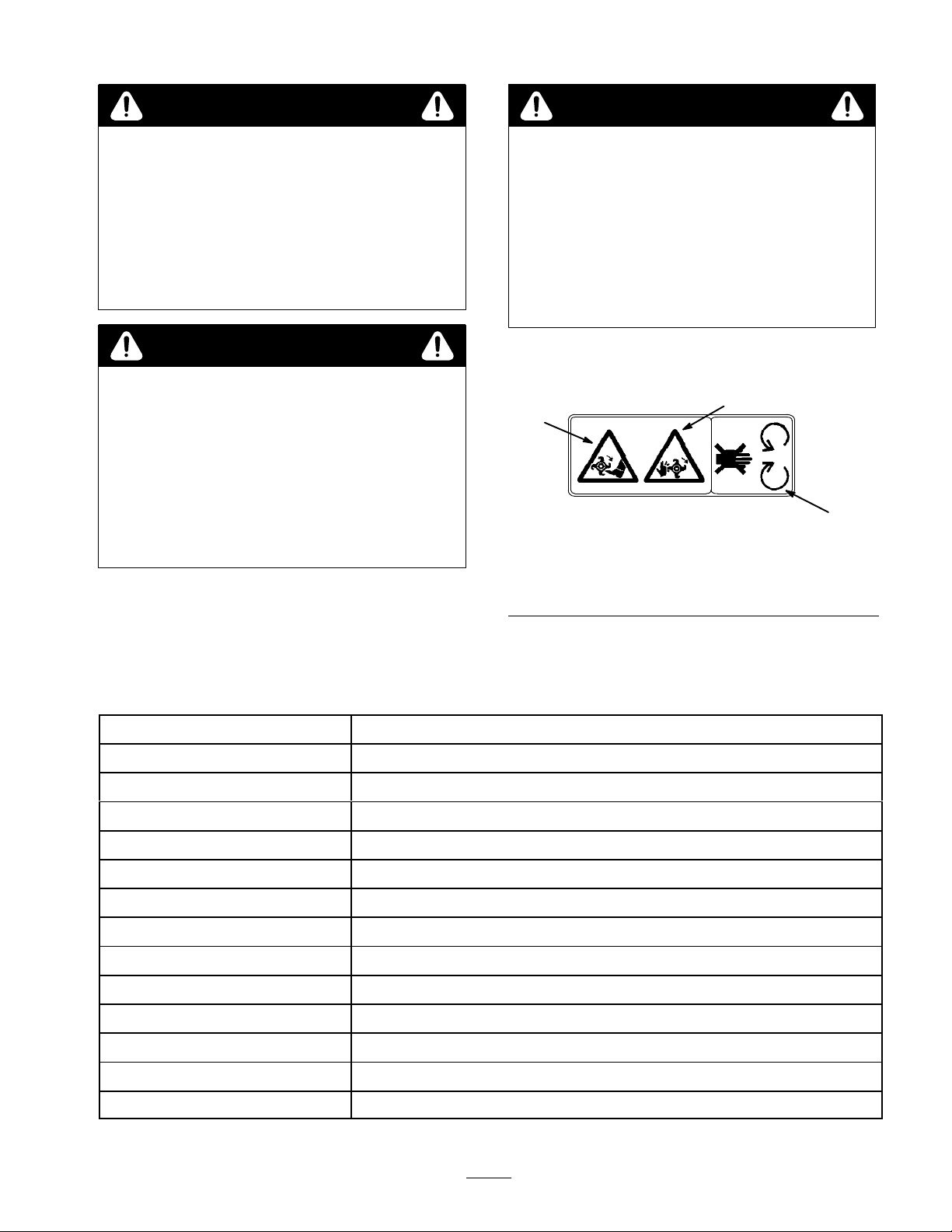
Safety
1
1. Cutting
2.
O AVOID THE HAZARD
Always lower the loader arms befor
off the traction unit.
Decals
2
#
93–7321
Figure 1
hazard–foot
Cutting hazard–hand
3.
Keep away from moving
parts
.
ed by
e you shut
3
Specifications
Overall
Overall length
Overall height
T
T
T
T
T
T
Number of tines
Shaft diameter
Drive
Hydraulic motor displacement
Weight
width
illing width
ine diameter
ine speed (max)
ine speed (recommended)
ine thickness
ine width
44.0 inches (1
20.0 inches (51 cm)
26.0 inches (66 cm)
40.0 inches (102 cm)
19.0 inches (48 cm)
245 rpm @ 3600 engine rpm (flow divider @ 9 o’clock position)
225 rpm @ 3600 engine rpm (flow divider @ 10 o’clock position)
.25 inches (.63 cm)
2.5 inches (6.4 cm)
36
1.50 inches (3.8 cm)
Chain ANSI 60 reduction ratio 1.8:1
6.20 cu. in. (102 cc)
363 lbs (165 kg)
12 cm)
3
Page 4

Stability
To
determine the degree of slope you can traverse with the
tiller installed on a traction unit, find the stability rating
for the hill position you want to travel in the table below
then find the degree of slope for the same rating and hill
position in the Stability Data section of the traction unit
operator’
Orientation
Front Uphill
Ratings
s manual.
Stability Rating
C
Rear Uphill
C
Side Uphill
B
1.
Position the tiller on a level surface with enough space
behind it to accommodate the traction unit.
2.
Move pump control lever to slow (turtle) position.
,
3.
Start the engine.
4.
Slowly push the attachment tilt lever forward to tilt the
attachment mount plate forward.
5.
Position mount plate into the upper lip of the
attachment receiver plate (Fig. 2).
1
2
1. Mount
Figure
plate
2
2.
Receiver plate
m–4055
Note:
The tiller is rated for use without the counterweight.
If you use the counterweight with the tiller
unit will be less stable in the front and side uphill
positions.
, the traction
WARNING
POTENTIAL HAZARD
•
Exceeding the maximum slope can cause the
traction unit to tip.
WHA
T CAN HAPPEN
•
If the traction unit tips, you or bystanders could
be crushed.
HOW T
•
O AVOID THE HAZARD
Do not drive the the traction unit on a slope
steeper that the maximum slope.
Installation
Installing
the Tiller on the
6. Raise
IMPORTANT
enough to clear the gr
all the way back.
7.
8.
1. Quick
the loader arms while tilting back the mount
plate at the same time.
: The attachment should be raised
ound and the mount plate tilted
Stop the engine.
Engage the quick attach pins (Fig. 3).
1
Figure
attach pins (shown in engaged position)
m–4056
3
T
raction Unit
IMPORTANT:
the traction unit, ensur
of any dirt or debris.
Befor
e connecting any attachments to
e that the mount plates ar
e fr
ee
Connecting
Hoses
1. Stop
4
the engine.
the Hydraulic
Page 5

2.
Move the auxiliary hydraulic lever forward, backward,
and back to neutral to relieve hydraulic pressure at the
hydraulic couplers.
7.
Start the engine, tilt the mount plate forward and back
the traction unit away from the tiller
.
IMPORTANT
cleaned fr
3.
Remove protective covers from hydraulic couplers on
the traction unit. Connect covers together to prevent
contamination during operation.
4.
Slide the collars back on the hydraulic couplers and
connect the attachment couplers to the traction unit
couplers.
Ensure that the connections are secure by pulling on
5.
the hoses.
: Ensur
om hydraulic couplers.
e that all for
eign matter is
WARNING
POTENTIAL HAZARD
•
Hydraulic fluid escaping under pr
penetrate skin and cause injury
WHA
T CAN HAPPEN
•
Fluid accidentally injected into the skin must be
surgically r
doctor familiar with this form of injury
gangr
HOW T
•
Keep body and hands away from pin hole leaks
or nozzles that eject high pr
fluid.
Use cardboard or paper to find hydraulic leaks,
•
never use your hands.
emoved within a few hours by a
ene may r
O AVOID THE HAZARD
esult.
.
essur
essur
e can
, or
e hydraulic
Operation
Tips
• Clean
•
•
• T
• A
•
•
•
for T
the area of trash, branches, and rocks before
tilling to prevent equipment damage.
Always begin tilling with the slowest ground speed
possible. Increase speed if conditions permit.
Always use full throttle (maximum engine speed).
ill in long, straight passes. Do not make turns while
the tiller is in the ground, as equipment damage may
result.
void excessive tilling of the soil, as finely tilled soil
will not absorb moisture easily and puddles of water or
run-of
f may occur
When tilling hard packed, very dry
the tiller so only the very top of the soil is penetrated.
On succeeding passes the depth may be lowered.
Run the tiller so that the dirt is thrown away from you.
If a rock or other obstruction gets into the tiller tines,
reverse the rotation direction to dislodge it.
illing
.
, or vir
gin soil, raise
Removing
T
raction Unit
1. Start
2.
3.
4.
5.
IMPORTANT
to pr
storage.
6.
engine and lower the tiller to the ground or onto a
trailer.
Stop the engine.
Move the auxiliary hydraulic lever forward, backward,
and back to neutral to relieve hydraulic pressure at the
hydraulic couplers.
Disengage the quick attach pins by turning them to the
outside.
Slide the collars back on the hydraulic couplers and
disconnect them.
event hydraulic system contamination during
Install the protective covers onto the hydraulic
couplers on the traction unit.
the T
: Connect the attachment hoses together
iller from the
5
Page 6

Maintenance
Service
Service
Shaft bearing–lubricate
Chain tension–adjust and lubricate
Tines–check X
T
ine bolts–check and tighten
Chipped surfaces–paint
Interval Chart
Operation
POTENTIAL
•
If you leave the key in the ignition switch, someone could start the engine.
WHA
T CAN HAPPEN
•
Accidental starting of the engine could seriously injur
HOW T
•
Remove the key fr
HAZARD
O AVOID THE HAZARD
om the ignition switch befor
Each
Use5Hours25Hours
X X
initial X
X
CAUTION
e you or other bystanders.
e you do any maintenance.
Storage
Service
X
Notes
Replace as required
Replace as required
Greasing
and Lubrication
Service Interval/Specification
Grease
the 2 tiller shaft fittings every 25 operating hours.
Grease immediately after every washing.
Grease T
ype: General-purpose grease.
How to Grease
1. Lower
2.
3.
4.
5.
6. W
the loader arms and stop the engine. Remove
the key
.
Clean the grease fittings with a rag.
Scrape any paint of
Connect a grease gun to each fitting.
Pump grease into the fittings until grease begins to
ooze out of the bearings.
ipe up any excess grease.
f the front of the fittings.
Lubricating Tiller Drive Chain
Lubricate
operation and every 25 operating hours thereafter
tiller drive chain after the initial 5 hours of
Lubricant T
1.
Lower the loader arms and stop the engine. Remove
the key
Remove the chain drive cover (Fig, 4).
2.
3.
Apply a commercial chain lube onto the chain spans.
4.
Install the chain drive cover
ype: Commercial chain lube.
.
.
Adjusting Tiller Drive Chain
Tension
Adjust
the tiller drive chain after the initial 5 hours of
operation and every 25 operating hours thereafter
should be 1/2–3/4 inch slack in the chain, measured
mid–way between the sprockets.
1.
Lower the loader arms and stop the engine. Remove
the key
.
Remove the chain drive cover (Fig, 4).
2.
3.
Loosen the 2 hydraulic motor
(Fig, 4).
4.
Using the adjuster bolt, move the hydraulic motor
.
upward to tighten the chain (Fig, 4).
, mount plate bolts
. There
6
Page 7

ines should be installed as illustrated in Figure 5 with 2
T
left hand tines and 2 right hand tines on each hub.
2
3
1
2
1. Chain
2.
Hydraulic motor
plate bolt
5. After
Figure
drive cover
, mount
proper chain tension is attained, tighten the
4
3.
Adjuster bolt
adjuster bolt and hydraulic motor mount plate bolts
(Fig, 4).
Note:
When proper adjustment can no longer be attained
from the adjuster bolt or repeated chain failures occur
replace chain.
6.
Install the chain drive cover
.
m–4372
,
2
1
2
Figure
1. Left
hand tine
The
cutting edges of the tines should face toward the rear
of the tiller
orque the tine mounting bolts to 70 ±7 in–lb.
T
.
5
2.
Right hand tine
Storage
1.
Before long term storage wash the tiller with mild
deter
gent and water to remove dirt and grime.
2.
Check the condition of the drive chain. Adjust and
lubricate the chain.
3.
Grease all fittings.
4.
Check and tighten all bolts, nuts, and screws. Repair or
replace any part or tines that are damaged or worn.
5.
Paint all scratched or bare metal surfaces. Paint is
available from your Authorized Service Dealer
1
m–4414
.
Tiller Tine Replacement
Check
and replace tines when they become worn or dull.
W
orn or dull tines will degrade the performance of the
tiller.
Store the tiller in a clean, dry garage or storage area.
6.
Cover the tiller to protect it and keep it clean.
7
Page 8

Troubleshooting
PROBLEM POSSIBLE
T
iller does not operate.
CAUSES
1.
Hydraulic coupler not
completely connected
2.
Defective hydraulic coupler
3.
An obstruction in a hydraulic
hose
4.
Auxiliary valve on the traction
unit is not opening.
5.
An obstruction in the tiller
(e.g., rock or root)
6.
Broken drive chain
7.
Loose drive chain
8.
Defective hydraulic valve
9.
Defective drive motor
CORRECTIVE ACTION
1.
Check and tighten all couplers.
2.
Check couplers and replace
any that are defective.
3.
Find and remove the
obstruction.
4.
Repair the valve.
5.
Find and remove the
obstruction.
6.
Repair or replace the chain.
7.
Adjust the chain tension.
8.
Replace or repair the defective
valve.
9.
Replace or repair the drive
motor.
8
 Loading...