

Page 1
FORM NO. 3321–604
Breaker
Attachment
Model No. 22441– 990001 & Up
Operator’s Manual
IMPORTANT: Read this manual carefully. It contains information about your
safety and the safety of others. Also become familiar with the controls and
their proper use before you operate the product.
Page 2

Introduction
We want you to be completely satisfied with your
new product, so feel free to contact your local
Authorized Service Dealer for help with service,
genuine replacement parts, or other information you
may require.
Whenever you contact your Authorized Service
Dealer or the factory, always know the model and
serial numbers of your product. These numbers will
help the Service Dealer or Service Representative
provide exact information about your specific
product. You will find the model and serial number
on a plate located on the breaker frame.
For your convenience, write the product model and
serial numbers in the space below.
Model No:
Serial No.
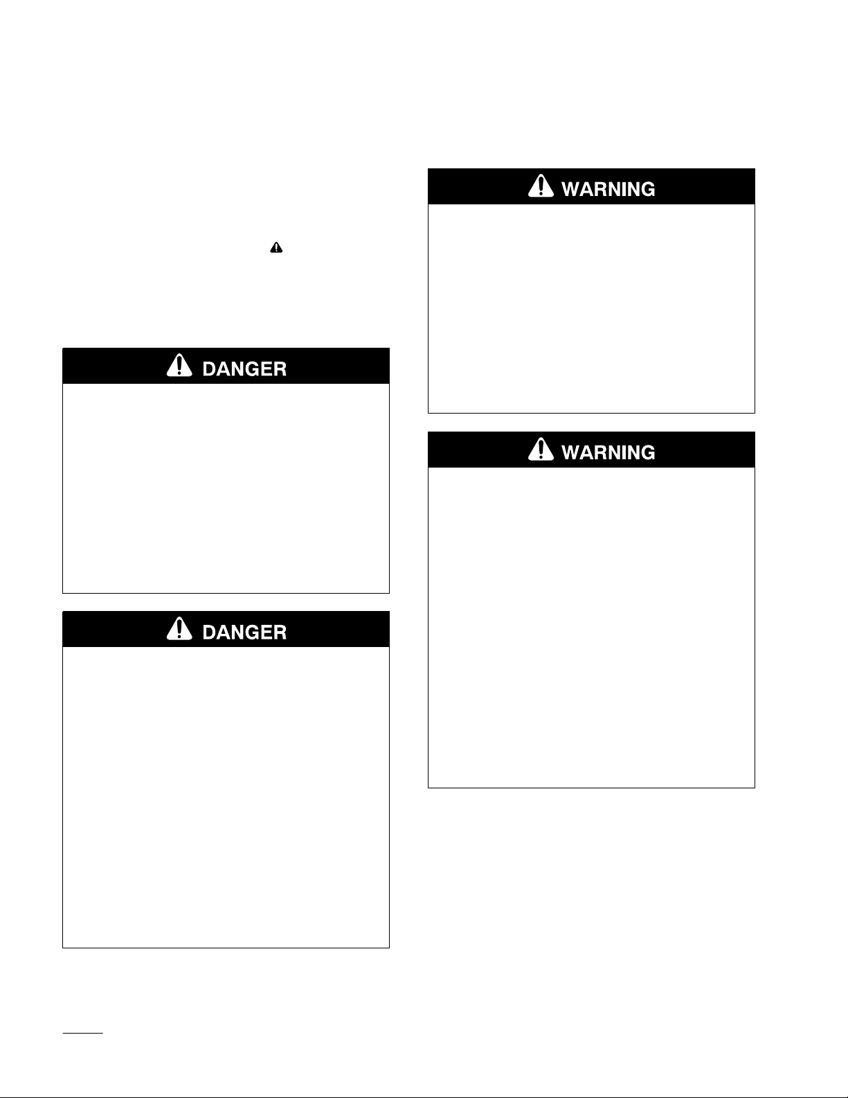
The warning system in this manual identifies
potential hazards and has special safety messages that
help you and others avoid personal injury, even death.
DANGER, WARNING and CAUTION are signal
words used to identify the level of hazard. However,
regardless of the hazard, be extremely careful.
DANGER signals an extreme hazard that will cause
serious injury or death if the recommended
precautions are not followed.
WARNING signals a hazard that may cause serious
injury or death if the recommended precautions are
not followed.
CAUTION signals a hazard that may cause minor or
moderate injury if the recommended precautions are
not followed.
Two other words are also used to highlight
information. “Important” calls attention to special
mechanical information and “Note” emphasizes
general information worthy of special attention.
The left and right side of the machine is determined
by standing in the normal operator’s position.
Printed in USA
Page 3

Contents
Page
Safety 2.
Specifications 4
Installation 5
. . . . . . . . . . . . . . . . . . . . . . . . . . . . . . . .
Safety and Instruction Decals 3
. . . . . . . . . . . . . . . . . . . . . . . . . . .
General Specifications: 4
. . . . . . . . . . . . . . . . . . . . . . . . . . . . .
Loose Parts 5
Installing the Breaker on the Traction Unit 5
Installing the Bit 6
Connecting the Hydraulic Hoses7. . . . . . . .
Removing the Breaker from the
Traction Unit 7
. . . . . . . . . . . . . . . . . . . . . . . . .
. . . . . . . . . . . . . . . . . . . . .
. . . . . . . . . . . . . . . . . . . . . .
. . . . . . . . . .
. . . . . . . . . . . . . . .
Page
Operation 8
Maintenance 10
Troubleshooting 12
. . . . . . . . . . . . . . . . . . . . . . . . . . . . . .
Operating Tips 8
Breaking a Vertical Surface 9
. . . . . . . . . . . . . . . . . . . . . . . . . . . .
Service Interval Chart 10
Greasing the Bit 10
Storage 11
. . . . . . . . . . . . . . . . . . . . . . . . . . . .
. . . . . . . . . . . . . . . . . . . . . .
. . . . . . . . . . . .
. . . . . . . . . . . . . . . .
. . . . . . . . . . . . . . . . . . . . .
. . . . . . . . . . . . . . . . . . . . . . . . .
1
Page 4
Safety
Improper use or maintenance by the operator or
owner can result in injury. To reduce the potential
for injury, comply with the safety instructions in
the traction unit operator’s manual and always
pay attention to the safety alert
means CAUTION, WARNING, or
DANGER—“personal safety instruction.” Failure
to comply with the instruction may result in
personal injury or death.
symbol, which
POTENTIAL HAZARD
• When the engine is off, attachments in the
raised position can gradually lower.
WHAT CAN HAPPEN
• Someone nearby may be pinned or injured
by the attachment as it lowers.
POTENTIAL HAZARD
• There may be buried power, gas, and/or
telephone lines in the work area.
WHAT CAN HAPPEN
• Shock or explosion may occur.
HOW TO AV
OID THE HAZARD
• Have the property or area to be broken
marked for buried lines and do not break
in marked areas.
POTENTIAL HAZARD
• Contact with moving breaker may cause
injury.
WHAT CAN HAPPEN
• Moving breaker can crush hands, feet or
other body parts.
HOW TO AV
OID THE HAZARD
• Always lower the attachment lift each time
you shut off the traction unit.
POTENTIAL HAZARD
• During operation, the breaker thr
pieces of broken material and dust.
WHAT CAN HAPPEN
ows small
• Flying debris may damage eyes.
• Inhaling the dust can damage lungs.
HOW TO AV
OID THE HAZARD
• The operator and all bystanders must wear
safety glasses, goggles, or a face shield
during operation of the breaker.
• The operator and all bystanders must wear
a face mask or other filter over mouths and
noses during operation of the breaker.
• Keep bystanders at least 25 feet away from
the beaker during operation.
HOW TO AV
OID THE HAZARD
• Keep your hands, feet, and any other part
of your body or clothing away from moving
parts.
• Before adjusting, cleaning, repairing, and
inspecting the breaker, lower it to the
ground, stop the engine, remove the key,
and wait for all moving parts to stop.
2
Page 5
POTENTIAL HAZARD
• The breaker is very loud during operation.
WHAT CAN HAPPEN
• Over time, your hearing may be impaired if
unprotected.
Safety
HOW TO AV
OID THE HAZARD
• Wear hearing protection during operation.
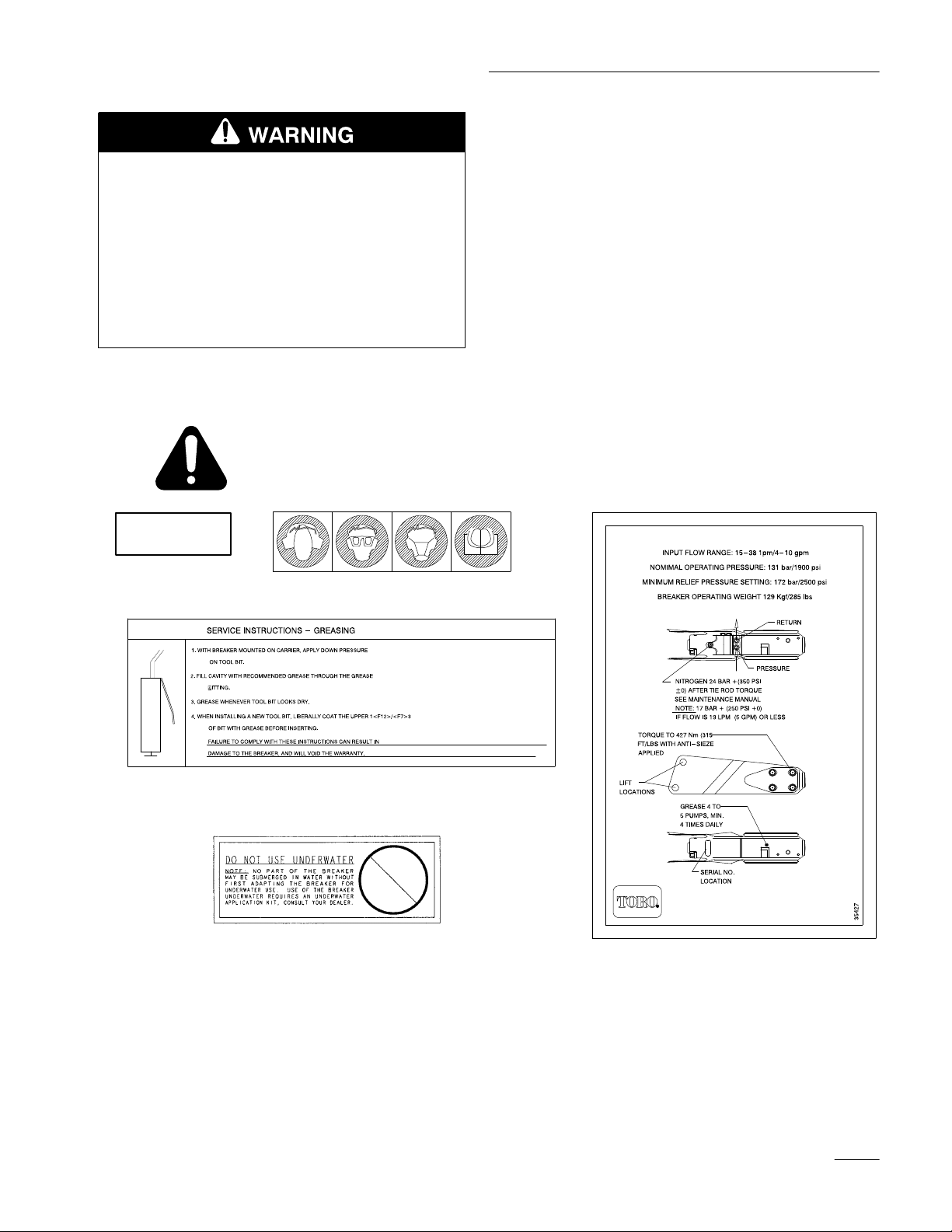
Safety
and Instruction Decals
Safety decals and instructions are easily visible to the operator and are located near
any area of potential danger. Replace any decal that is damaged or lost.
(Part No. 2771
1)
(Part No. 28886)
(Part No. 26068)
(Part No. 35487)
(Part No. 35427)
3
Page 6

Specifications
General
Overall width 24.5 inches (62 cm)
Overall length 49.0 inches (125 cm)
Overall height 13.0 inches (33 cm)
Weight (with bit) 285 lbs (129 Kg)
Bit working length 11.0 inches (27.9 cm)
Bit diameter 1.75 inches (4.4 cm)
Impact ener
Blows per minute 1200
Flow range 4 to 10 gpm (15 to 38 lpm)
Specifications:
gy class
175 ft·lbs (237 J)
4
Page 7

Installation
Loose
DESCRIPTION QTY. USE
Breaker
Bit–concrete
contact your T
Installing
T
raction Unit
Parts
breaker (other bits are available;
oro dealer for more information)
IMPORTANT: The Hydraulic Relief kit must
be installed on some traction units prior to
using the breaker or serious damage may
occur to the hydraulic system. Failure to
install the relief kit will void the warranty of
your traction unit. To determine if your
traction unit needs a Hydraulic Relief Kit,
contact your authorized Toro dealer.
the Breaker on the
IMPORTANT: Before installing the breaker,
ensure that the mount plates are free of any
dirt or debris.
1
1
Assemble the breaker
2. Move pump control lever to slow (turtle)
position.
3. Start the engine.
4. Slowly push the attachment tilt lever forward to
tilt the attachment mount plate forward.
5. Position mount plate into the upper lip of the
attachments receiver plate (Fig. 1).
2
1
1. Position the breaker on a level surface with
enough space behind it to accommodate the
traction unit.
Figure 1
1. Mount
6. Raise the loader arms while tilting back the
plate
mount plate at the same time.
IMPORTANT: The attachment should be
raised enough to clear the ground and the
mount plate tilted all the way back.
2.
Receiver plate
m–4055
5
Page 8

Installation
7. Stop the engine.
8. Engage the attachment lock pins (Fig. 2).
1
1
3
4
Figure 2
1. Attachment
Installing
lock pins (shown in engaged position)
the Bit
1. Raise the horizontal breaker so it is about 6
inches off of the ground.
2. Stop the engine and remove the key.
3. Using a hammer and punch, drive the bit
retaining pin 3/4 of the way out of the breaker
housing (Fig. 3). It will require a blow of
considerable force to drive the pin from its
seating in the breaker.
m–4056
2
m–4248
Figure 3
1. Retaining
2. Bit
pin
3. Notch
4.
Grease here
4. Remove the plastic spacer.
5. Smear grease completely over the top six inches
of the bit (Fig. 3).
6. Slide the bit into the breaker with the notch in
the bit facing the right side of the breaker
(Fig. 3).
7. Insert the bit retaining pin into the breaker and
drive it into place with a hammer (Fig. 3).
8. Grease the bit before use. For detailed
instructions on when and how to grease the bit,
refer to Greasing the Bit, page 10.
Note: To change bits, repeat the above
procedure. When changing bits the
current bit will be removed instead of
the plastic spacer
6
.
Page 9

Installation
Connecting
the Hydraulic
Hoses
1. Stop the engine.
2. Move the auxiliary hydraulics lever forward,
backward, and back to neutral to relieve pressure
at the hydraulic couplers.
IMPORTANT: Ensure that all foreign matter
is cleaned from the hydraulic connections
before making connections.
3. Remove the protective covers from the hydraulic
couplers on the traction unit. Connect the covers
together to prevent contamination during
operation.
4. Ensure that the hydraulic hoses on the breaker
are routed through the loop on the top of the
mount plate.
5. Slide the collar back on the hydraulic coupler
and connect the attachment couplers to the
machine couplers.
5. Slide the collar back on the hydraulic couplers
and disconnect them.
IMPORTANT: Connect the attachment hoses
together to prevent hydraulic system
contamination during storage.
POTENTIAL HAZARD
• Hydraulic fluid escaping under pressure
can penetrate skin and cause injury.
WHAT CAN HAPPEN
• Fluid accidentally injected into the skin
must be surgically removed within a few
hours by a doctor familiar with this form of
injury or gangrene may result.
HOW TO AV
OID THE HAZARD
• Keep body and hands away from pin hole
leaks or nozzles that eject high pressure
hydraulic fluid.
• Use cardboard or paper to find hydraulic
leaks, never use your hands.
6. Confirm that the connection is secure by pulling
on the hoses.
Removing
T
raction Unit
1. Start the engine and lower the breaker to the
ground or onto a trailer.
2. Stop the engine.
3. Disengage the attachment lock pins by turning
them to the outside.
4. Move the auxiliary hydraulics lever forward,
backward, and back to neutral to relieve pressure
at the hydraulic couplers.
the Breaker from the
6. Install the protective covers onto the hydraulic
couplers on the traction unit.
7. Start the engine, tilt the mount plate forward,
and back the traction unit away from the breaker.
7
Page 10

Operation
Operating Tips
• Always use full throttle (maximum engine
speed) when breaking.
• Use low range (turtle position) on the speed
selector for best performance and smoothest
operation.
• Adjust the flow divider valve to approximately
the 10 o’clock position.
• Place the bit within 6 to 18 inches of the edge of
the material to be broken with the breaker angled
slightly towards the edge (Fig. 4).
• When breaking, always apply downward
pressure with the loader arms until the front
wheels raise off of the ground a few inches
(Fig. 4). Maintain this pressure as the bit works
its way into the material being broken.
• Do not move the auxiliary hydraulics lever to
engage the breaker unless the bit is on the
ground and downward pressure is applied.
• Do not bind the bit in the material being cut.
Binding of the bit can cause the bit to bend or
wear out prematurely. Ensure that all force
applied to the breaker is inline with the bit, not
side to side or front to back. This will require
frequent adjustments in the positioning of the
traction unit.
• Listen to the sound of the breaker when is is
operating. The sound will be different when
there is adequate downward pressure than when
not enough pressure is being applied.
m–4249
Figure 4
• If the bit is positioned too far from the edge of
the material the energy may be absorbed by the
material without breaking it. If the material has
not cracked after 15 to 20 seconds, stop the
breaker and move the bit to a different location.
IMPORTANT: Continuous penetration in the
same location for long periods of time will
create high temperatures at the tip of the bit.
This could cause the bit to lose its temper and
mushroom under impact, destroying the bit.
• Many materials do not respond well to continued
hammering in one place. Move the the breaker
each time that it penetrates the material without
breaking it. When you move the breaker to a
new location, move it in a line parallel to the
edge of the material, about 3 inches from the
previous hole. This will score the material and if
done repeatedly, break off a large piece of the
material (Fig. 5).
8
Page 11

m–4250
Operation
1
2
1
Figure 5
IMPORTANT: Never pry with the bit.
• If you are breaking rebar reinforced concrete, use
a chisel bit in the breaker to cut through the
rebars in the concrete. The rebar can also be cut
with a torch.
IMPORTANT: Do not use the breaker in or
under water.
Breaking
a V
ertical Surface
Converting the Breaker
1. Tilt the breaker as far forward as possible and
lower it until the tip is resting on the ground.
2. Remove the click pin securing the front
mounting pin (Fig. 6).
2
Figure 6
1. Click
pin
2.
Front mounting pin
Operating Tips for Vertical Surfaces
• Position the bit on the vertical surface in the
same manner as you would position it on a
horizontal surface.
• Maintain pressure on the bit by driving the
traction unit forward into the vertical surface
while operating the breaker.
m–4251
3. Drive the front mounting pin out of the breaker
(Fig. 6).
4. Lower the loader arms until the holes in the
breaker align with the upper holes in the mount
(Fig. 6).
5. Drive the front mounting pin through the upper
holes and secure it with the click pin (Fig. 6).
9
Page 12

Maintenance
Service
Service
Grease the bit
Inspect and tighten all fasteners
Inspect the mounting pins, holes, lower bushing
(above the bit), bit retaining pin, and roll pins for
looseness or wear
Check for hydraulic leaks at all fittings and hoses.
Chipped surfaces—paint
Interval Chart
Operation
.
POTENTIAL HAZARD
• If you leave the key in the ignition switch, someone could start the engine.
WHAT CAN HAPPEN
• Accidental starting of the engine could seriously injure you or other bystanders.
Each
Use
X X
X X
X X
X X
Storage
Service
X
Notes
Grease before each use and then
every 1 to 2 operating hours
Reseat or replace as necessary
Repair leaky fittings and/or replace
leaky hoses.
.
HOW TO AV
OID THE HAZARD
• Remove the key from the ignition switch before you do any maintenance.
Greasing
the Bit
Service Interval/Specification
Grease the bit before each use and then after every 1
to 2 hours of operation. Grease it immediately after
washing.
Grease Type: General-purpose grease, certified NGLI
number 1 or 2.
How to Grease
1. Tilt the breaker so that it is vertical, then lower it
to the ground so that the bit is pushed up into the
breaker as far as possible.
IMPORTANT: Failure to push the bit up into
the breaker before greasing will allow the
grease to fill the space between the top of the
bit and the breaker piston. When you next
use the breaker, the piston will pr
grease and cause seal damage.
2. Stop the engine and remove the key.
essurize this
10
Page 13

3. Clean the grease fitting with a rag.
Maintenance
POTENTIAL HAZARD
• Hydraulic fluid escaping under pressure
can penetrate skin and cause injury.
WHAT CAN HAPPEN
• Fluid accidentally injected into the skin
must be surgically removed within a few
hours by a doctor familiar with this form of
injury or gangrene may result.
m–4152
Figure 7
4. Connect a grease gun to the fitting.
5. Pump grease into the fitting until either grease
begins to ooze out of the lower bushing and
retaining pin or it becomes difficult to pump the
grease gun.
6. Wipe up any excess grease.
Storage
1. Before long term storage, wash the machine with
mild detergent and water to remove dirt and
grime from the entire machine.
HOW TO AV
OID THE HAZARD
• Keep body and hands away from pin hole
leaks or nozzles that eject high pressure
hydraulic fluid.
• Use cardboard or paper to find hydraulic
leaks, never use your hands.
6. Ensure that all hydraulic couplers are connected
together to prevent contamination of the
hydraulic system.
7. Paint all scratched or bare metal surfaces. Paint
is available from your Authorized Service
Dealer.
8. Store the breaker in a vertical position in a
clean, dry garage or storage area. Cover it to
protect it and keep it clean.
IMPORTANT: If the breaker will be stored
for more than a month, it must be stored
vertically to avoid damaging o–rings and
seals inside the breaker.
2. Grease the bit.
3. Check and tighten all bolts, nuts, and screws.
4. Inspect all mounting pins, holes, the lower
bushing, roll pins, and the bit retaining pin.
Repair or replace any part that is damaged or
worn.
5. Inspect all hydraulic fittings and hoses for leaks.
Repair or replace any fittings or hoses that leak.
11
Page 14

Troubleshooting
PROBLEM
The breaker does not operate.
POSSIBLE CAUSES
1.
Hydraulic coupler not
completely connected
2.
Damaged hydraulic coupler
3.
An obstruction in a hydraulic
hose
4.
Auxiliary valve on the traction
unit is not opening.
5.
Low nitrogen level in the
breaker
CORRECTIVE ACTION
1.
Check and tighten all
couplers.
2.
Check couplers and replace
any that are damaged.
3.
Find and remove the
obstruction.
4.
Repair the valve.
5.
Refer to you authorized T
dealer.
oro
12
Page 15

Page 16

 Loading...