

Page 1
Form No. 3323-274
Tree
Forks
Sitework Systems Attachment
Model No. 22438—890001 & Up
Operator’s Manual
English (CE)
Page 2
Contents
Page
Introduction 2.
Safety 2
Safety Decals3. . . . . . . . . . . . . . . . . . . . . . . . . . . . .
Specifications 4
Stability Ratings4. . . . . . . . . . . . . . . . . . . . . . . . . . .
Operation 5
T
ree Fork Operation5. . . . . . . . . . . . . . . . . . . . . . . .
Operating T
T
ree Fork Controls5. . . . . . . . . . . . . . . . . . . . . . . . .
Maintenance 5
Service Interval Chart5. . . . . . . . . . . . . . . . . . . . . .
Storage 6
Troubleshooting 6
. . . . . . . . . . . . . . . . . . . . . . . . . . . . . . . .
. . . . . . . . . . . . . . . . . . . . . . . . . . . . . . . . . . . . . .
. . . . . . . . . . . . . . . . . . . . . . . . . . . . . . . .
. . . . . . . . . . . . . . . . . . . . . . . . . . . . . . . . . . .
ips 5
. . . . . . . . . . . . . . . . . . . . . . . . . . . .
. . . . . . . . . . . . . . . . . . . . . . . . . . . . . . . . .
. . . . . . . . . . . . . . . . . . . . . . . . . . . . . . . . . .
. . . . . . . . . . . . . . . . . . . . . . . . . . . . . .
Introduction
W
e want you to be completely satisfied with your new
product, so feel free to contact your local Authorized
Service Dealer for help with service, genuine replacement
parts, or other information you may require.
Whenever you contact your Authorized Service Dealer or
the factory
your product. These numbers will help the Service Dealer
or Service Representative provide exact information about
your specific product. Y
number on a plate located on the back of the tree fork
frame.
For your convenience, write the product model and serial
numbers in the space below
, always know the model and serial numbers of
ou will find the model and serial
.
Model No:
DANGER
serious injury or death if the recommended precautions
are not followed.
WARNING
or death if the recommended precautions are not followed.
CAUTION
moderate injury if the recommended precautions are not
followed.
wo other words are also used to highlight information.
T
“Important” calls attention to special mechanical
information and “Note” emphasizes general information
worthy of special attention.
The left and right side of the machine is determined by
standing in the normal operator’s position.
signals an extreme hazard that will cause
signals a hazard that may cause serious injury
signals a hazard that may cause minor or
Safety
Impr
oper use or maintenance by the operator or owner
can r
esult in injury
comply with the safety instructions in the traction unit
Operator’
safety alert
W
ARNING, or DANGER—“personal safety
instruction.” Failur
may r
POTENTIAL HAZARD
• Ther
WHA
•
HOW T
•
s Manual and always pay attention to the
esult in personal injury or death.
e may be buried power
telephone lines in the work ar
T CAN HAPPEN
Shock or explosion may occur
O AVOID THE HAZARD
Have the pr
buried lines and don’t dig in marked ar
. T
o r
educe the potential for injury
symbol, which means CAUTION,
e to comply with the instruction
DANGER
, gas, and/or
ea.
.
operty or work ar
ea marked for
eas.
,
Serial No.
The
warning system in this manual identifies potential
hazards and has special safety messages that help you and
others avoid personal injury
W
ARNING and CAUTION are signal words used to
identify the level of hazard. However
hazard, be extremely careful.
, even death. DANGER,
, regardless of the
The Toro Company – 1999
8111 Lyndale Ave. South
Bloomington, MN 55420–1196
2
All Rights Reserved
Printed in the USA
Page 3
DANGER
CAUTION
POTENTIAL HAZARD
• Ther
WHA
•
HOW T
•
e may be overhead power lines in the work
area.
T CAN HAPPEN
Shock may occur if a power line is touched by a
tr
ee or other object that is being transported.
O AVOID THE HAZARD
Survey and mark the ar
overhead power lines, and do not transport
tr
ees or tall objects under the power lines.
ea wher
e ther
e ar
WARNING
POTENTIAL HAZARD
•
When the engine is off, attachments in the
raised position can gradually lower
WHA
T CAN HAPPEN
•
Someone nearby may be pinned or injur
the attachment as it lowers.
HOW T
•
O AVOID THE HAZARD
Always lower the attachment lift each time you
shut off the traction unit.
.
ed by
POTENTIAL HAZARD
•
If you step off of the platform with the load
raised, the machine could tip forward.
WHA
T CAN HAPPEN
•
Someone nearby may be pinned or injur
HOW T
•
e
O AVOID THE HAZARD
Lower the fork befor
platform.
e stepping off or the
ed.
CAUTION
POTENTIAL HAZARD
•
If the attachment is not kept level while lifting,
the load could be inadvertently dumped on the
operator.
WHA
T CAN HAPPEN
•
The operator could be injured when the fork is
unloaded.
HOW T
•
•
O AVOID THE HAZARD
When lifting the attachment, tilt it forward to
keep it level and pr
backwards.
Carry the load level and low to the gr
event it fr
om spilling
ound.
WARNING
POTENTIAL HAZARD
•
When going up or down hill, the machine could
overturn if the heavy end is toward the
downhill side.
WHA
T CAN HAPPEN
•
Someone may be pinned or seriously injured by
the machine if it overturns.
HOW T
•
O AVOID THE HAZARD
Operate up and down slopes with the heavy end
of the machine uphill. An empty fork will make
the r
ear end heavy and a loaded fork will make
the fr
ont end heavy
.
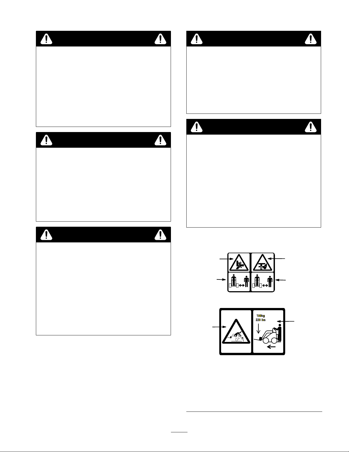
Safety
1. Pinching/crushing
hazard—hand
2. Pinching/crushing
hazard—foot
3. Keep
Decals
1
3
4
bystanders away
#
100–4650
# 100–4650
Figure 1
2
3
4.
Machine rollover–
exceeding rated load
capacity can cause
instability
5.
Maximum load capacity
5
3
Page 4

Specifications
Note:
Specifications and design are subject to change
without notice.
Overall
Overall length
Overall height
Weight
Fork length
Fork specifications
width
Length
Height
Width
Thickness
Cross section
Movement range
Left fork
Right fork
24.5 inches (62 cm)
45 inches (1
12.5 inches (32 cm)
169 lbs (77 Kg)
43 inches (109 cm)
43 inches (109 cm)
3 inches (7.6 cm)
3 inches (7.6 cm)
0.25 inches (0.6 cm)
Triangular
47 degrees
Stationary
14 cm)
WARNING
POTENTIAL HAZARD
•
Exceeding the maximum r
can cause the traction unit to tip.
WHA
T CAN HAPPEN
•
If the traction unit tips, you or bystanders could
be crushed.
HOW T
•
O AVOID THE HAZARD
Do not drive the traction unit on a slope steeper
than the maximum r
determined in the following tables and the
traction unit operator’s manual.
Stability without a Load
Orientation
Front Uphill
ecommended slope
ecommended slope, as
Stability Rating
Hydraulic cylinder
Rod diameter
Stroke
Bore diameter
Cylinder force
Pivot pin diameter
Maximum load
Stability
To
determine the degree of slope you can traverse with the
fork installed on a traction unit, find the stability rating for
the hill position you want to travel in the appropriate
table, then find the degree of slope for the same rating and
hill position in the Stability Data section of the traction
unit operator’s manual.
IMPORTANT
operator’
on the platform while using the fork, or the traction
unit will become unstable.
Ratings
: If your traction unit has a r
s platform, the counterweight must be used
1.125 inches (3 cm)
3 inches (7.6 cm)
2 inches (5 cm)
8,425 lbs (4,275 Kg) at
3,000 psi (20,685 kPa)
1 inches (2.5 cm)
220 lbs (100 Kg)
ear
Rear Uphill
Side Uphill
Stability with a Load
Orientation
Front Uphill
D
B
B
Stability Rating
C
4
Rear Uphill
C
Side Uphill
B
Page 5

Operation
Note:
Refer to your traction unit operator’s manual for
complete instructions on installing/removing attachments
onto/from the traction unit and connecting/disconnecting
hydraulic hoses.
Note:
Always use the traction unit to lift and move the
attachment.
•
Never attempt to lift more that the rated capacity of
the traction unit.
•
When transporting a load, keep the fork as close to the
ground as possible.
• T
o ease the placement of a tree into a hole, pick up the
tree near the top of the ball or container
The fork can also be used to lift, transport, and
•
position small boulders and rocks.
.
Tree
The
and container grown trees and shrubs. Y
the fork to move rocks under 220 lbs (100 Kg).
T
tree ball or container
position the tree between the forks. Gently angle the forks
inward until they contact the tree ball or container
the loader arms to lift the tree.
Fork Operation
tree fork is an excellent tool for transporting balled
ou can also use
o pick up a tree, angle the forks to a width larger than the
. Drive the traction unit forward to
. Raise
Operating Tips
• Position
to maximize lifting capability
the tree as close as possible to the fork frame
.
Maintenance
Service
Service
Interval Chart
Operation
Each
Use5Hours25Hours
Tree
1. If
2.
3.
Fork Controls
your traction unit has a speed selector and a flow
divider
, move the speed selector to the fast (rabbit)
position and the flow divider to the 10 to 1
position.
Pull the auxiliary hydraulics valve to the operator grip
to open the forks.
Push the auxiliary hydraulics valve away from the
operator grip to close the forks.
200
Hours
Storage
Service
1 o’clock
Notes
Hydraulic hoses—inspect
Chipped surfaces—paint
POTENTIAL
•
If you leave the key in the ignition switch, someone could start the engine.
WHA
T CAN HAPPEN
•
Accidental starting of the engine could seriously injur
HOW T
•
Remove the key fr
HAZARD
O AVOID THE HAZARD
CAUTION
om the ignition switch befor
X X
e you or other bystanders.
e you do any maintenance.
5
Replace if damaged
X
Page 6

Storage
1.
Before long term storage, wash the attachment with
mild deter
2.
Check and tighten all bolts, nuts, and screws. Repair or
replace any part that is damaged or worn.
gent and water to remove dirt and grime.
Troubleshooting
3.
Ensure that all hydraulic couplers are connected
together to prevent contamination of the hydraulic
system.
Paint all scratched or bare metal surfaces. Paint is
4.
available from your Authorized Service Dealer
Store the attachment in a clean, dry garage or storage
5.
area. Cover it to protect it and keep it clean.
.
PROBLEM POSSIBLE
Fork does not open and close.
CAUSES
1.
Hydraulic coupler not
completely connected
2.
Defective hydraulic coupler
3.
An obstruction in a hydraulic
hose
4.
Auxiliary valve on the traction
unit is not opening.
5.
Defective hydraulic cylinder(s)
CORRECTIVE ACTION
1.
Check and tighten all couplers.
2.
Check couplers and replace
any that are defective.
3.
Find and remove the
obstruction.
4.
Repair the valve.
5.
Replace or repair any defective
cylinders.
6
Page 7

7
Page 8

 Loading...