

Page 1
Form No. 3323–284
Over–the–Tire Tracks
Model 22457 and 22431
IMPORTANT:
all pr
ecautions listed ther
Loose
DESCRIPTION QTY. USE
Pivot
pin
Hex set–screw
Wheel spacers
Lug nuts (20 provided with the wheel spacers
and 20 on the traction unit)
Over–the–tire track assembly
Bolt
Locknut
Befor
Parts
e using this pr
e.
oduct, r
ead the safety section in your traction unit operator’s manual, and follow
2
2
4
40
2
4
4
Install on loader arm hydraulic cylinders
Install on wheels
Install on traction unit
Installation
Instructions
Installation
IMPORTANT:
the Sitework Systems or turf tread tir
over any other type of tir
machine.
Installing Pivot Pins
Model
22457 Only
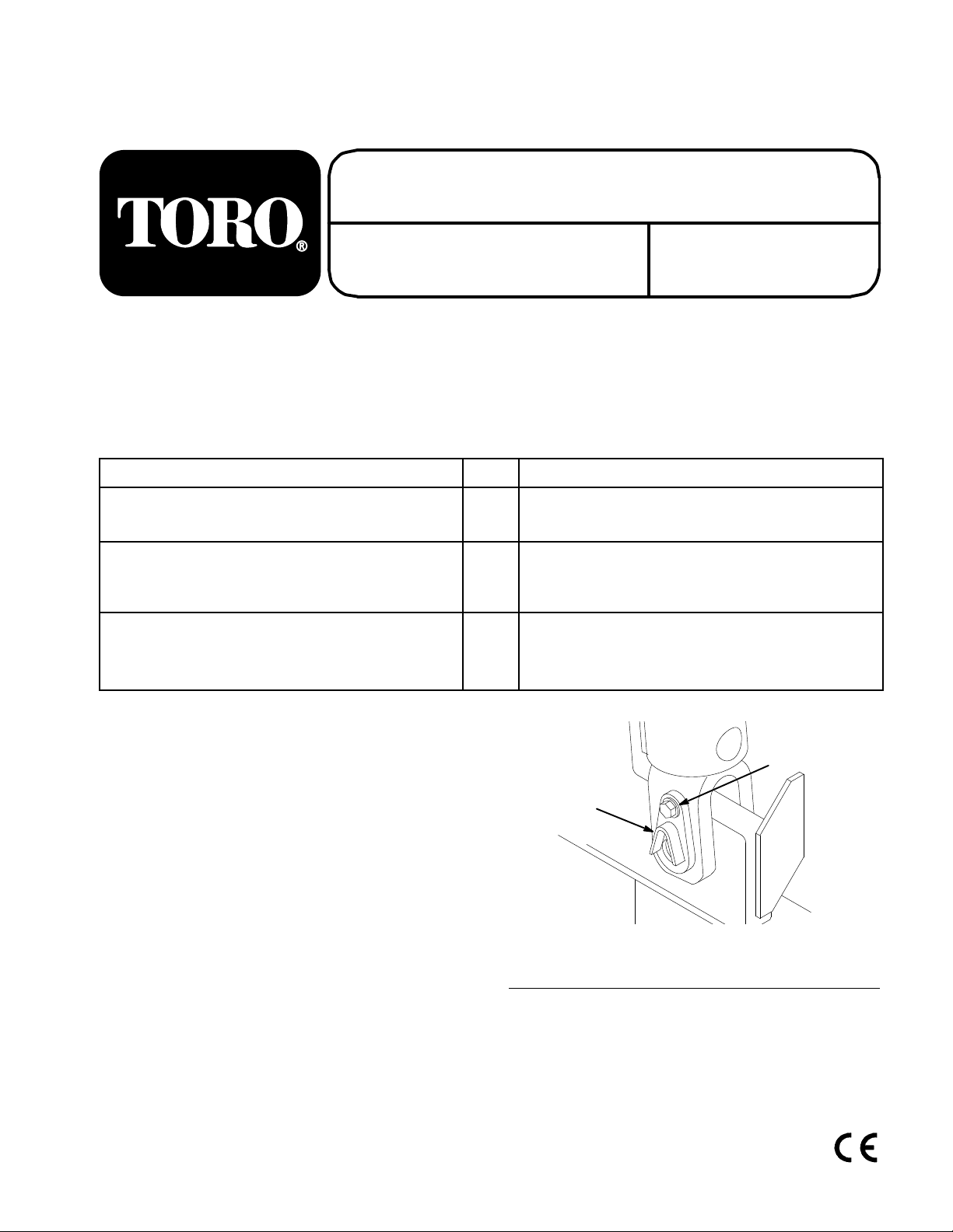
1.
Lower the loader arms as low as possible.
2. T
urn the traction unit of
Remove the existing pivot pin from the bottom of a
3.
loader arm hydraulic cylinder (Fig. 1). Retain the bolt
for later use.
The T
8111 Lyndale Ave. South
Bloomington, MN 55420–1196
The tracks must only be installed over
es. Installation
oro Company
e may r
– 1999
esult in damage to the
f and remove the key
.
1
1. Pivot
4. Remove
pin
the grease fitting from the center of the pivot
pin and discard the pin.
Figure
2
m–3933
1
2. Bolt
All Rights Reserved
Printed in the USA
Page 2
Installation Instructions
5.
Install the new pivot pin using the bolt removed in step
3 (Fig. 2).
3
4
1
2
3
1. Pivot
2. Bolt
pin
6. Thread
Figure
the grease fitting removed from the old pivot
2
Hex set–screw
3.
pin into the opening in the face of the new pivot pin.
7.
Connect a grease gun to the fitting. Pump grease into
the fitting until grease begins to ooze out of the
bearing.
ipe up any excess grease.
8. W
9.
Remove the grease fitting and replace it with the hex
set-screw (Fig. 2).
10.
Repeat steps 3 through 9 for the other loader arm
hydraulic cylinder
Store the grease fittings for future use (refer to
11.
.
Greasing Pivot Pins, page 3).
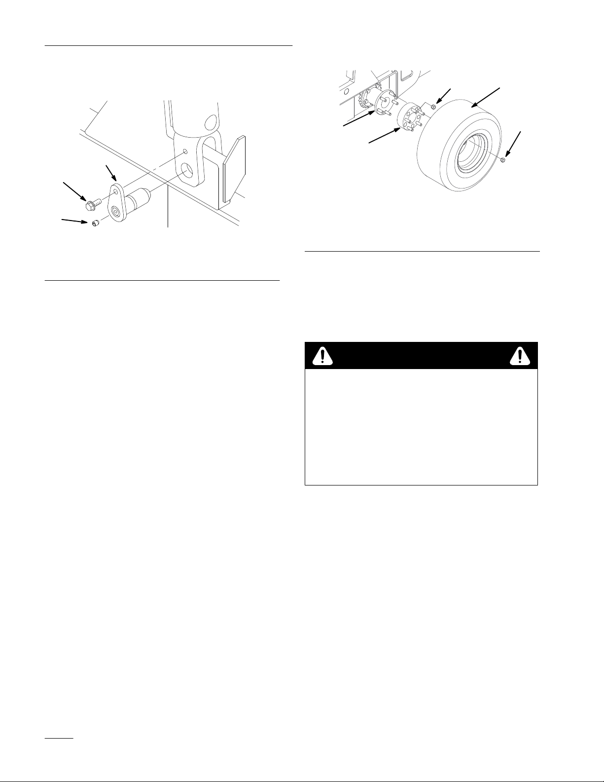
Installing Wheel Spacers
1. Put
the traction unit up on blocks and remove the
wheels.
Slide the wheel spacers onto the studs on the wheel
2.
hub and secure them with lug nuts
(Fig. 3). T
3.
Install the wheels on the studs on the wheel spacers
and secure them with lug nuts (Fig. 3). T
nuts to 55 ft-lbs (75 N·m).
orque the lug nuts to 55 in–lbs (75 N·cm).
orque the lug
m–3935
2
1
Figure
1. Wheel
2.
4. Return
5.
spacer
Wheel hub
the traction unit to the ground.
After the first 8 hours of operation, torque the lug nuts
3
3.
Lug nut
4. Wheel
again to 55 ft-lbs (75 N·m).
Installing the Tracks
CAUTION
POTENTIAL
•
Some ar
moving parts that can pinch.
WHA
T CAN HAPPEN
• Y
ou could be cut or pinched while handling the
tracks.
HOW T
• W
ear leather gloves while handling the tracks.
1.
Lay one track on a level surface.
2.
Drive the traction unit onto the track until both wheels
on one side are centered in the track.
3.
Pull the front and rear of the track up and over the tires
and secure them with a ratchet and straps (Fig. 4).
4.
Connect the track by installing (2) bolts and (2)
locknuts through the connector links on both sides of
the track (Fig. 4).
HAZARD
eas of the tracks have sharp edges and
O AVOID THE HAZARD
3
m–3900
2
Page 3

Installation Instructions
5
2
4
3
Figure
1. Track
2. Bolt
3. Locknut
5. Remove
6.
Repeat steps 1 through 4 for the other side of the
the ratchet and straps.
4
4. Connector
5.
Rachet and straps
link
traction unit.
7.
Drive the traction unit for a few minutes to loosen the
tracks.
Lay a long, straight bar across the top of each track.
8.
There should be 1 to 3 in. (25 to 76 cm) of slack in the
top span of the track below the bar (Fig. 5).
1
m–3899
Remove the bolts and nuts from the connector links
2.
and lay the track flat.
3.
Drive slowly of
4.
Place the bolts and nuts in the holes in the connector
f of the track.
for storage.
5.
Repeat steps 1 through 4 for the other track.
Operating Tips
WARNING
POTENTIAL
•
The moving tracks can pinch hands or feet.
WHA
T CAN HAPPEN
•
Injury or amputation could r
HOW T
•
Keep clear of the tracks during operation.
A
void operating on asphalt or concrete surfaces as damage
may occur to the surface, as well as excessive wear on the
tracks.
HAZARD
esult.
O AVOID THE HAZARD
Maintenance
1
Figure
1. 1
to 3 in. (25 to 76 cm)
9. If
there is too much or too little slack in the track,
5
adjust the track tension; refer to Adjusting T
ension, page 4.
T
Removing the Tracks
1. Stop
the traction unit so that one set of the bolted
connector links on a track is in the middle of the top
span.
rack
m–3898
Greasing Pivot Pins
Model
22457 Only
Grease the pivot pins on the hydraulic cylinders as
instructed in the traction unit Operator’s Manual. T
grease the pivot pins installed with the tracks, complete
the following procedure:
1.
Lower the loader arms as far as possible.
2. T
urn the traction unit of
Clean the face of each pivot pin with a rag.
3.
4.
Remove the hex set–screws from the center of the
f and remove the key
pivot pins.
5.
Thread the grease fittings removed from the old pivot
pins during installation into the openings vacated by
the set–screws.
6.
Connect a grease gun to each fitting. Pump grease
into the fittings until it begins to ooze out of the
bearings.
ipe up any excess grease.
7. W
8.
Remove the grease fittings and replace them with the
hex set–screws.
o
.
3
Page 4

Installation Instructions
Adjusting Track Tension
Check
the tension of the tracks every 25 operating hours
by laying a long, straight bar across the top of each track.
There should be 1 to 3 in. (25 to 76 cm) of slack in the top
span of the track below the bar (Fig. 5). If the track needs
adjustment, complete the following procedure:
Note:
When you adjust the traction drive chain (if you
traction unit has traction drive chains), the track may also
need to be adjusted.
1.
Park the traction unit so that one set of the bolted
connector links is in the middle of the top span.
2.
Remove the bolts from the connector and reconnect
them through the inner holes of the track section to
tighten the track (Fig. 6).
Note: T
o loosen the track you can move a connector
installed in an inner hole to the outer hole.
2
4
3
1. Track
2. Bolt
3. Check
Figure
the track tension and repeat steps 1 and 2 for
6
3. Locknut
4. Connector
link
one of the other adjustable track sections if additional
tensioning is required.
m–3899
1
Storage
1.
Before long term storage, wash the tracks with mild
deter
gent and water to remove dirt and grime.
2.
Check the condition of the tracks and tighten all bolts
and nuts. Repair or replace any part that is damaged or
worn.
Store the tracks in a clean, dry garage or storage area.
3.
Cover them to protect them and keep them clean.
4
 Loading...