

FormNo.3395-258RevB
StumpGrinder
CompactUtilityLoaders
ModelNo.22429—SerialNo.315000001andUp
Registeratwww.T oro.com.
OriginalInstructions(EN)
*3395-258*B

WARNING
CALIFORNIA
Proposition65Warning
Thisproductcontainsachemicalorchemicals
knowntotheStateofCaliforniatocausecancer,
birthdefects,orreproductiveharm.
Useofthisproductmaycauseexposureto
chemicalsknowntotheStateofCalifornia
tocausecancer,birthdefects,orother
reproductiveharm.
ThisproductcomplieswithallrelevantEuropeandirectives.
Fordetails,pleaseseetheDeclarationofIncorporation(DOI)
atthebackofthispublication.
Introduction
ThismachineisdesignedforuseonTorocompactutility
loaderstogrindandremovetreestumpsandsurfaceroots.It
isnotintendedtocutrockoranyothermaterialotherthan
woodandthesoilaroundastump.
Readthisinformationcarefullytolearnhowtooperateand
maintainyourproductproperlyandtoavoidinjuryand
productdamage.Youareresponsibleforoperatingthe
productproperlyandsafely.
g013652
Figure1
1.Modelandserialnumberlocation
ModelNo.
SerialNo.
Thismanualidentiespotentialhazardsandhassafety
messagesidentiedbythesafetyalertsymbol(Figure2),
whichsignalsahazardthatmaycauseseriousinjuryordeath
ifyoudonotfollowtherecommendedprecautions.
YoumaycontactTorodirectlyatwww .Toro.comforproduct
safetyandoperationtrainingmaterials,accessoryinformation,
helpndingadealer,ortoregisteryourproduct.
Wheneveryouneedservice,genuineT oroparts,oradditional
information,contactanAuthorizedServiceDealerorToro
CustomerServiceandhavethemodelandserialnumbersof
yourproductready.Figure1identiesthelocationofthe
modelandserialnumbersontheproduct.Writethenumbers
inthespaceprovided.
g000502
Figure2
1.Safetyalertsymbol
Thismanualuses2wordstohighlightinformation.
Importantcallsattentiontospecialmechanicalinformation
andNoteemphasizesgeneralinformationworthyofspecial
attention.
©2016—TheToro®Company
8111LyndaleAvenueSouth
Bloomington,MN55420
Contactusatwww.Toro.com.
2
PrintedintheUSA.
AllRightsReserved

Contents
Safety
Safety...........................................................................3
StabilityRatings.......................................................5
SafetyandInstructionalDecals.................................5
Setup............................................................................6
1AssemblingtheOperatorShield..............................6
2InstallingtheChipGuard.......................................8
ProductOverview..........................................................8
Specications.........................................................8
Attachments/Accessories.........................................8
Operation.....................................................................9
GrindingStumps.....................................................9
GrindingRoots......................................................10
TransportingtheStumpGrinderonaTrailer..............10
OperatingTips......................................................10
Maintenance.................................................................11
RecommendedMaintenanceSchedule(s)......................11
GreasingtheMachine.............................................11
ReplacingtheTeeth................................................12
Storage........................................................................12
Troubleshooting...........................................................13
Improperuseormaintenancebytheoperatororowner
canresultininjury.Toreducethepotentialforinjury,
complywiththesesafetyinstructionsandthoseinthe
tractionunit
thesafetyalertsymbol,whichmeans
or
Danger
complywiththeinstructionmayresultinpersonalinjury
ordeath.
Operator's Man ual
—personalsafetyinstruction.Failureto
.Alwayspayattentionto
Caution
,
W ar ning
DANGER
Theremaybeburiedpower,gas,and/ortelephone
linesintheworkarea.Shockorexplosionmay
occurifyoudigintothem.
Havethepropertyorworkareamarkedforburied
linesanddonotdiginmarkedareas.Contactyour
localmarkingserviceorutilitycompanytohavethe
propertymarked(forexample,intheUnitedStates,
call811forthenationwidemarkingservice).
DANGER
,
Thestumpgrinderissolelydesignedandtestedfor
usegrindingstumpslessthan91cm(36inch)tall.
Anyotherusesmaycauseahazardoussituation
resultingininjuryordeathtoyouorbystanders.
Onlyusethestumpgrinderforgrindingstumps
lessthan91cm(36inch)tall.
WARNING
Whentheengineisoff,attachmentsintheraised
positioncangraduallylower.Someonenearbymay
bepinnedorinjuredbytheattachmentasitlowers.
Alwayslowertheattachmentlifteachtimeyoushut
offthetractionunit.
WARNING
Duringoperation,debriswillyinalldirections
andcancauseinjurytoeyesandotherexposed
bodyparts.
•Neveroperatethestumpgrinderwithoutthe
shieldinstalledonthetractionunitandthechip
guardonthegrinder.
•Wearpersonalprotectivegearduringoperation.
•Keepallbystandersatleast9m(30feet)away
fromtheworkarea.
3

WARNING
CAUTION
Whengoingupordownhill,themachinecould
overturniftheheavyendistowardthedownhill
side.Someonemaybepinnedorseriouslyinjured
bythemachineifitoverturns.
Operateupanddownslopeswiththeheavyendof
themachineuphill.Thisattachmentwillmakethe
frontendheavy.
WARNING
Ifyoudonotfullyseattheattachmentlocking
pinsintheattachmentmountplateholes,the
attachmentcouldfalloffofthetractionunitseverely
injuringtheoperatororbystanders.
•Ensurethatyoufullyseattheattachment
lockingpinsthroughtheholesintheattachment
mountplatebeforeliftingtheattachment.
•Ensurethattheattachmentmountplateisfreeof
anydirtordebristhatmayhindertheconnection
ofthetractionunittotheattachment.
Hydrauliccouplers,hydrauliclines/valves,and
hydraulicuidmaybehotandcanburnyouifyou
touchthem.
•Weargloveswhenoperatingthehydraulic
couplers.
•Allowthetractionunittocoolbeforetouching
hydrauliccomponents.
•Donottouchhydraulicuidspills.
•Refertoyourtractionunit
fordetailedinformationonsafelyconnectingan
attachmenttoyourtractionunit.
Operator’ s Man ual
WARNING
Lightningcancausesevereinjuryordeath.If
lightningisseenorthunderisheardinthearea,do
notoperatethemachine;seekshelter.
CAUTION
Hydraulicuidescapingunderpressurecan
penetrateskinandcauseinjury.Fluidinjectedinto
theskinmustbesurgicallyremovedwithinafew
hoursbyadoctorfamiliarwiththisformofinjury
organgrenemayresult.
•Keepyourbodyandhandsawayfrompin
holeleaksornozzlesthatejecthighpressure
hydraulicuid.
•Usecardboardorpapertondhydraulicleaks,
neveruseyourhands.
4
StabilityRatings
Todeterminethedegreeofslopeyoucantraversewith
thestumpgrinderinstalledonatractionunit,ndthe
stabilityratingforthehillpositionyouwanttotravelinthe
appropriatetablebelow ,thenndthedegreeofslopeforthe
sameratingandhillpositionintheStabilityDatasectionof
thetractionunitOperator’ sManual.
WARNING
Exceedingthemaximumrecommendedslope
cancausethetractionunittotip,crushingyouor
bystanders.
Donotdrivethetractionunitonaslopesteeper
thanthemaximumrecommendedslope,as
determinedinthefollowingtablesandthetraction
Operator's Man ual
unit
Important:IfyouhaveatractionunitotherthanaTX
compactutilityloader,donotusethecounterweight
.
SafetyandInstructionalDecals
onthetractionunitwhenusingthestumpgrinder.If
youusethecounterweight,thetractionunitwillbeless
stableinthefrontandsideuphillpositions.
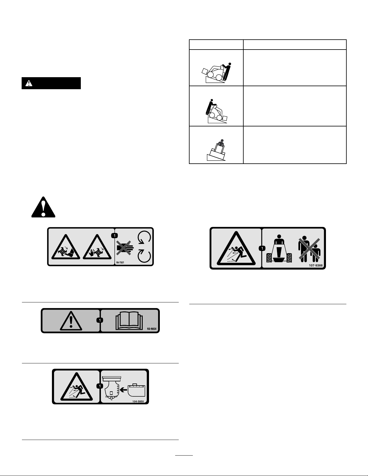
OrientationStabilityRating
FrontUphill
D
RearUphill
C
SideUphill
C
Safetydecalsandinstructionsareeasilyvisibletotheoperatorandarelocatednearanyareaofpotential
danger.Replaceanydecalthatisdamagedorlost.
93-7321
1.Cutting/dismembermenthazardofhandsandfeet,rotating
knives/blades—stayawayfrommovingparts.
93-9854
1.Warning—readtheOperator’sManual.
decal93-7321
107-9366
1.Thrownobjecthazard—keepbystandersasafedistance
fromthemachine.
decal93-9854
decal107-9366
104-5850
1.Thrownobjecthazard—donotoperatewithoutthechip
guardproperlyinstalled.
decal104-5850
5

Setup
g013653
1
2
3
4
LooseParts
Usethechartbelowtoverifythatallpartshavebeenshipped.
ProcedureDescription
1
2
1
AssemblingtheOperator Shield
Rightshieldbracket1
Leftshieldbracket
Self-tappingscrew(5/16x3/4inch)
Shieldsupport
Shield
Bolt(1/4x1-1/2inch)
Washer6
Locknut(1/4inch)
TXbracketmountingtemplate1
Chipguard
Guardpin
Hairpincotter1
Qty.
Use
1
4
2
1
6
6
1
1
Assembletheoperatorshield.
Installthechipguard.
Partsneededforthisprocedure:
1Rightshieldbracket
1
Leftshieldbracket
4
Self-tappingscrew(5/16x3/4inch)
2
Shieldsupport
1
Shield
6
Bolt(1/4x1-1/2inch)
6Washer
6
Locknut(1/4inch)
1TXbracketmountingtemplate
InstallingtheShieldBracketona200
or300SeriesTractionUnit
1.Insertthetabontheshieldbracketintotheliftpoint
holeonthetractionunit,withtheholeinthebracket
aligningwiththesmallholeinthetractionunitframe
(Figure3).
Note:Thereisarightandleftbracket.Ensurethat
youinstallthecorrectbracketoneachside.Thetab
shouldbeintheliftpointholeandthebracketshould
beontheoutsideoftheframe(Figure3).
Figure3
1.Shieldbracket
2.Lift-pointhole4.Self-tappingscrew
2.Securethebrackettotheframewithaself-tapping
screw(Figure3).
3.Repeatsteps1and2fortheothersideofthetraction
unit.
3.Tab
InstallingtheShieldBracketonaTX
TractionUnit
1.Measureinfromtheedgesoftheframeasillustrated
inFigure4andmarkthelocationsoftheholesfor
mountingtheshieldbracket.
Note:Iftheholesexist,skiptostep3.
g013653
6

g013654
0.56 inch
(1.42 cm)
1.8 inch
(4.57 cm)
1.8 inch
(4.57 cm)
1
g013655
1
2
Figure5
g013656
1
2
3
4
5
6
7
1.Self-tappingscrew2.Shieldbracket
4.Securethebrackettotheframewith2self-tapping
screwsasillustratedinFigure5.
5.Repeatsteps1through4fortheothersideofthe
tractionunit.
AssemblingtheShield
g013655
g013654
Figure4
1.Mountingholes
bracketsonthetractionunit(Figure6).
2.Drillahole(5/16inchdiameter)throughtheframe
ateachmarkedlocation.
3.Alignthetabontheshieldbracketwiththefrontedge
oftheframewiththebracketinsideoftheloaderarm
pocket(Figure5).
1.Slidetheshieldsupportsintothepocketsintheshield
Note:Thereisarightandleftbracket.Ensurethat
youinstallthecorrectbracketoneachside.Thetab
shouldbeovertheframeedgeandthebracketshould
beinsidetheloaderarmpocketwiththe2smaller
holesinthebracketlinedupwiththeholesyoudrilled
intheframe(Figure5).
g013656
Figure6
1.Locknut
2.Washer
3.Shield7.Shieldbracket
4.Bolt
5.Skirt
6.Shieldsupport
7

2.Assembletheshieldandexibleskirttotheshield
g013657
1
2
3
4
5
supportsasillustratedinFigure6,using6bolts(1/4x
1-1/2inch),washers,andlocknuts(1/4inch).
Note:Theskirtshoulddrapeovertheengineorhood.
2
InstallingtheChipGuard
Partsneededforthisprocedure:
1
Chipguard
1
Guardpin
1Hairpincotter
ProductOverview
Procedure
Thestumpgrinderhas4setsofmountingholesfor
positioningthechipguard(Figure7).Movetheguardup
(upperholes)whenyouaregrindingclosetothegroundand
down(lowerholes)whenyouarechippingtallstumps.Install
thechipguardasfollows:
1.Positionthemountingtubeontheguardbetween2
holesonthegrinder(Figure7).
Figure7
1.Guardpin
2.Mountingholes5.Hairpincotter
3.Chipguard
4.Mountingtube
g013651
Figure8
1.Chipguard4.Stumpgrindinghead
2.Mountingplate5.Teeth
3.Pivotbolt
Specications
Note:Specicationsanddesignaresubjecttochange
withoutnotice.
Width,withchipguard
Width,withoutchipguard
Length
Height
Weight
Attachments/Accessories
AselectionofToroapprovedattachmentsandaccessoriesis
availableforusewiththemachinetoenhanceandexpand
itscapabilities.ContactyourAuthorizedServiceDealeror
Distributororgotowww .Toro.comforalistofallapproved
g013657
attachmentsandaccessories.
112cm(44inches)
66cm(26inches)
51cm(20inches)
79cm(31inches)
120Kg(265lb)
2.Slidetheguardpinthroughtheholesinthegrinder
andthemountingtube(Figure7).
3.Securethepinwithahairpincotter(Figure7).
8

Operation
WARNING
Duringoperation,debriswillyinalldirections
andcancauseinjurytoeyesandotherexposed
bodyparts.
•Neveroperatethestumpgrinderwithoutthe
shieldinstalledonthetractionunitandthechip
guardonthegrinder.
•Wearpersonalprotectivegearduringoperation.
•Keepallbystandersatleast30feet(9m)away
fromtheworkarea.
RefertoyourtractionunitOperator’sManualformore
informationoninstallingandremovingattachmentsonyour
tractionunit.
Important:Alwaysusethetractionunittoliftandmove
theattachment.
GrindingStumps
5.Swingthegrindertowardyouusingtheattachment
tiltlever,grindingatadepthof0.5to5cm(1/4to
2inches),dependingonthehardnessofthewood
(Figure9).
Note:Ifyoutaketoodeepofacut,thegrinderwill
stall.Ifitstalls,raiseitslightlyandtryagain.
6.Swingthegrinderbackout(Figure9),lowerit0.5to5
cm(1/4to2inches)andrepeatsteps4through6until
youhavegrounddownafewinches.
7.Raisetheloaderarmstotheoriginalheight.
8.Movethegrindertotheright(Figure9).
9.Repeatsteps4through8untilyoureachtherightside
ofthestump.
10.Returnthegrindertotheleftsideofthestump,lower
it,andrepeatsteps3through10untilyouhaveground
thestumpintotheground.
Note:Tocontainthechips,youmayneedtostopthe
grinderandmovethechipguardupasyoumovethe
grinderdown.
11.Whennished,stopthegrinderbymovingtheauxiliary
hydraulicsleverintoneutral.
1.Ifyourtractionunithasaspeedselector,setittothe
Slow(turtle)position.
2.Starttheengine.
3.Pulltheauxiliaryhydraulicslevertotheoperatorgrip
toengagethestumpgrinder.
4.Positionthegrinderontheleftsideandbehindthe
stump(Figure9).
Figure9
g013658
9

GrindingRoots
1.Stopthegrinderandhangitverticallyfromtheloader
armsafewcentimeters(inches)offtheground.
2.Stoptheengineandremovethekey.
3.Loosenthelargeboltonthetopofthegrinder(Figure
10).
TransportingtheStump GrinderonaTrailer
Placetheattachmentonatrailerortruckcapableofcarrying
it.Securelytieittothetrailerortruckusingtiestraps
appropriatefortheweightoftheattachmentandforhighway
use.
Important:Removetheoperator'sshieldbefore
transportingthetractionunittoavoiddamagetothe
shieldofthetractionunit.
OperatingTips
•Alwaysusefullthrottle(maximumenginespeed).
•Nevertransporttheattachmentwiththeloaderarms
raised.Keepthearmsloweredandtheattachmenttilted
up.
•Ifyourtractionunithasaspeedselector(presentonsome
wheeledtractionunits),setittotheslow(turtleposition).
•Ifyourtractionunithasaowdivider(presentonsome
wheeledtractionunits),adjustittoapproximatelythe10
o’clockposition.
Figure10
1.Largebolt—loosen2.Frontbolt—remove
4.Removethefrontboltandnutsecuringthegrinder
(Figure10).
5.Swingthegrinder30degreesclockwise(Figure10).
6.Torquethelargeboltontopofthegrinderto406N-m
(300ft-lb)(Figure10)
7.Installtheboltandnutinthefrontholeandtorque
themto101N-m(75ft-lb)(Figure10).
8.Startthetractionunitandstartthegrinder.
9.Lowerthegrinderintotheroot.
10.Movethegrinderalongthelengthoftherootby
movingthetractionunitovertheroot.
11.Whennished,stopthegrinderbymovingtheauxiliary
hydraulicsleverintoneutral.
12.Loosenthelargeboltonthetopofthegrinder(Figure
10).
13.Removethefrontboltandnutsecuringthegrinder
(Figure10).
14.Swingthegrinder30degreescounter-clockwise(Figure
10).
15.Torquethelargeboltontopofthegrinderto406N-m
(300ft-lb)(Figure10).
16.Installtheboltandnutinthefrontholeandtorque
themto101N-m(75ft-lb)(Figure10).
g013659
10

Maintenance
RecommendedMaintenanceSchedule(s)
MaintenanceService
Interval
Beforeeachuseordaily
Beforestorage
MaintenanceProcedure
•Greasethemachine.
•Checktheconditionoftheteethandrotateorreplaceanythatarewornordamaged.
•Greasethemachine.
•Paintchippedsurfaces.
CAUTION
Ifyouleavethekeyintheignitionswitch,someonecouldstarttheengine.Accidentalstartingofthe
enginecouldseriouslyinjureyouorbystanders.
Removethekeyfromtheignitionswitchbeforeyoudoanymaintenance.
GreasingtheMachine
ServiceInterval:Beforeeachuseordaily
Beforestorage
Grease2ttings,asshowninFigure11,everydayand
immediatelyaftereverywashing.
Figure11
GreaseType:General-purposegrease
1.Stoptheengineandremovethekey.
2.Cleanthegreasettingswitharag.
3.Connectagreaseguntoeachtting.
4.Pumpgreaseintothettingsuntilgreasebeginsto
oozeoutofthebearings.
5.Wipeupanyexcessgrease.
g013660
11

ReplacingtheTeeth
ServiceInterval:Beforeeachuseordaily—Checkthe
conditionoftheteethandrotateor
replaceanythatarewornordamaged.
Duetothehighamountofwearplacedontheteeth,youwill
needtorotateandreplacethemperiodically.
Eachtoothisindexedwiththreepositionssoyoucanrotate
ittwice,exposinganewsharpedgebeforereplacingthe
tooth.Torotateatooth,loosenthenutsecuringthetooth
(Figure12).Pushthetoothforwardandrotateitonethird
ofaturn,bringinganunusededgetotheoutside.Torquethe
nutsecuringthetoothto37to45N-m(27to33ft-lb).
Storage
1.Beforelongtermstorage,brushthedirtfromthe
attachment.
2.Checktheconditionoftheteeth.Turnorreplaceany
wornordamagedteeth.
3.Checkandtightenallbolts,nuts,andscrews.Repairor
replaceanypartthatisdamagedorworn.
4.Ensurethatallhydrauliccouplersareconnected
togethertopreventcontaminationofthehydraulic
system.
5.Paintallscratchedorbaremetalsurfaces.Paintis
availablefromyourAuthorizedServiceDealer.
6.Storetheattachmentinaclean,drygarageorstorage
area.Coverittoprotectitandkeepitclean.
Figure12
(Yourgrinder'sappearancemayvaryfromthatshownin
theillustration)
1.Nut3.Tooth
2.Toothholder
Toreplaceatooth,removethenutsecuringthetoothto
removeit,theninstallanewtoothandnutinthesame
position(Figure12).Torquethenutsecuringthetoothto
37to45N-m(27to33ft-lb).
g013417
12

Troubleshooting
Problem
Cuttingdiskstopsduringcutting.
Thecuttingdiskdoesnotturn.
Thegrinderdoesnotcutfastenough.
PossibleCauseCorrectiveAction
1.Toodeepofacut.1.Raisetheloaderarms13mm(1/2
2.Teethworn,damaged,orbroken.2.Rotateorreplaceanyworn,damaged,
1.Ahydrauliccouplerisnotcompletely
connected.
2.Ahydrauliccouplerisdamaged.
3.Thereisanobstructioninahydraulic
hose.
4.Anauxiliaryvalveonthetractionunit
isnotopening.
5.Hydraulicmotororchaindrivefailure.5.ContactyourAuthorizedService
1.Wornteeth.1.Rotateorreplaceanywornteeth.
2.Wrongsettingonowdividerand
speedlever(applicablewheeledunits
only).
3.Thereisarestrictioninaquickcoupler
orhose.
4.Thehydraulicsystemistoohot.
5.Thereliefvalveissetbelow
specications.
inch).
orbrokenteeth.
1.Checkandtightenallcouplers.
2.Check/replacecouplers.
3.Findandremovetheobstruction.
4.Repairthevalve.
Dealer.
2.Settheowdividertothe10:00
positionandthespeedlevertothe
turtleposition.
3.Checkthehosesandcouplersand
repairanyproblemsfound.
4.Shutdownandallowthesystemto
cool.
5.ContactyourAuthorizedService
Dealer.
Thecuttingdiskturnsinthewrong
direction
1.Theauxiliaryvalveleverisinthewrong
position.
2.Thehydraulichosesarereversed.2.Disconnecthosesandswitchpositions.
1.Movetheauxiliaryvalvelevertothe
rearwardposition.
13

DeclarationofIncorporation
TheT oroCompany,8111LyndaleAvenueSouth,Bloomington,MN,USAdeclaresthatthefollowingunit(s)
conform(s)tothedirectiveslisted,wheninstalledinaccordancewiththeaccompanyinginstructionsontocertain
ToromodelsasindicatedontherelevantDeclarationsofConformity.
ModelNo.
22429315000001andUp
SerialNo.
ProductDescriptionInvoiceDescription
StumpGrinder
STUMPGRINDER
ATT ACHMENTCE
GeneralDescription
StumpGrinder2006/42/EC
Directive
RelevanttechnicaldocumentationhasbeencompiledasrequiredperPartBofAnnexVIIof2006/42/EC.
Wewillundertaketotransmit,inresponsetorequestsbynationalauthorities,relevantinformationonthispartly
completedmachinery.Themethodoftransmissionshallbeelectronictransmittal.
ThismachineryshallnotbeputintoserviceuntilincorporatedintoapprovedToromodelsasindicatedonthe
associatedDeclarationofConformityandinaccordancewithallinstructions,wherebyitcanbedeclaredin
conformitywithallrelevantDirectives.
Certied:EUTechnicalContact:
MarcelDutrieux
ManagerEuropeanProductIntegrity
ToroEuropeNV
Nijverheidsstraat5
2260Oevel
JoeHagerBelgium
Sr.EngineeringManager
811 1LyndaleAve.South
Bloomington,MN55420,USA
February4,2015
Tel.+3216386659

InternationalDistributorList
Distributor:
AgrolancKft
BalamaPrimaEngineeringEquip.HongKong85221552163
B-RayCorporation
CascoSalesCompany
CeresS.A.CostaRica
CSSCTurfEquipment(pvt)Ltd.SriLanka
CyrilJohnston&Co.
CyrilJohnston&Co.RepublicofIreland
EquiverMexico525553995444ParklandProductsLtd.NewZealand6433493760
FemcoS.A.Guatemala
ForGarderOU
G.Y .K.CompanyLtd.
GeomechanikiofAthensGreece
GolfinternationalTurizm
GuandongGoldenStarChina
HakoGroundandGardenSweden
HakoGroundandGarden
HayterLimited(U.K.)
HydroturfInt.CoDubai
HydroturfEgyptLLC
IrrimacPortugal351212388260ToroEuropeNVBelgium3214562960
IrrigationProductsInt'lPvtLtd.India0091442449
JeanHeybroekb.v.Netherlands31306394611VictusEmakPoland48618238369
Country:
Hungary3627539640
Korea82325512076
PuertoRico7877888383
NorthernIreland442890813121
Estonia3723846060
Japan81726325861
Turkey902163365993Riversa
Norway4722907760
UnitedKingdom441279723444
UnitedArabEmirates97143479479T-MarktLogisticsLtd.Hungary3626525500
Egypt2025194308ToroAustraliaAustralia61395807355
PhoneNumber:Distributor:
5062391138
94112746100
442890813121
5024423277
30109350054
862087651338
4635100000
4387
Country:
MaquiverS.A.Colombia
MaruyamaMfg.Co.Inc.
Mountelda.s.CzechRepublic
Mountelda.s.Slovakia
MunditolS.A.
NormaGarden
OslingerTurfEquipmentSA
OyHakoGroundandGarden
Ab
Perfetto
PratoverdeSRL.
Prochaska&Cie
RTCohen2004Ltd.
LelyTurfcare
SolvertS.A.S.
SpyprosStavrinidesLimitedCyprus
SurgeSystemsIndiaLimited
ValtechMorocco21253766
Japan81332522285
Argentina54114821
Russia749541 16120
Ecuador59342396970
Finland35898700733
Poland48618208416
Italy390499128
Austria4312785100
Israel97298617979
Spain
Denmark4566109200
France331308177
India911292299901
Phone
Number:
5712364079
420255704
220
420255704
220
9999
128
34952837500
00
35722434131
3636
EuropeanPrivacyNotice
TheInformationToroCollects
ToroWarrantyCompany(T oro)respectsyourprivacy.Inordertoprocessyourwarrantyclaimandcontactyouintheeventofaproductrecall,weaskyou
tosharecertainpersonalinformationwithus,eitherdirectlyorthroughyourlocalT orocompanyordealer.
TheT orowarrantysystemishostedonserverslocatedwithintheUnitedStateswhereprivacylawmaynotprovidethesameprotectionasapplies
inyourcountry.
BYSHARINGYOURPERSONALINFORMATIONWITHUS,YOUARECONSENTINGTOTHEPROCESSINGOFYOURPERSONALINFORMATION
ASDESCRIBEDINTHISPRIV ACYNOTICE.
TheWayT oroUsesInformation
Toromayuseyourpersonalinformationtoprocesswarrantyclaims,tocontactyouintheeventofaproductrecallandforanyotherpurposewhichwetell
youabout.ToromayshareyourinformationwithT oro'safliates,dealersorotherbusinesspartnersinconnectionwithanyoftheseactivities.Wewillnot
sellyourpersonalinformationtoanyothercompany.Wereservetherighttodisclosepersonalinformationinordertocomplywithapplicablelawsand
withrequestsbytheappropriateauthorities,tooperateoursystemsproperlyorforourownprotectionorthatofotherusers.
RetentionofyourPersonalInformation
Wewillkeepyourpersonalinformationaslongasweneeditforthepurposesforwhichitwasoriginallycollectedorforotherlegitimatepurposes
(suchasregulatorycompliance),orasrequiredbyapplicablelaw .
Toro'sCommitmenttoSecurityofYourPersonalInformation
Wetakereasonableprecautionsinordertoprotectthesecurityofyourpersonalinformation.Wealsotakestepstomaintaintheaccuracyandcurrent
statusofpersonalinformation.
AccessandCorrectionofyourPersonalInformation
Ifyouwouldliketorevieworcorrectyourpersonalinformation,pleasecontactusbyemailatlegal@toro.com.
AustralianConsumerLaw
AustraliancustomerswillnddetailsrelatingtotheAustralianConsumerLaweitherinsidetheboxoratyourlocalToroDealer.
374-0269RevH

TheToroUndergroundWarranty
ALimitedWarranty
Underground
Equipment
ConditionsandProductsCovered
TheToroCompanyanditsafliate,T oroWarrantyCompany,pursuant
toanagreementbetweenthem,jointlywarrantyourToroUnderground
Equipment(“Product”)tobefreefromdefectsinmaterialsorworkmanship.
Whereawarrantableconditionexists,wewillrepairtheProduct
atnocosttoyouincludingdiagnostics,labor,andparts.
ThefollowingwarrantyappliesfromthedatetheProductisdeliveredtothe
originalretailpurchaserorrentalowner.
ProductsWarrantyPeriod
EnginePoweredUnits&FluidMixers
AllSerializedAttachments
RockHammer6months
Engines
1yearor1000operatinghours,
whicheveroccursrst
1year
Throughenginemanufacturers:
2yearsor2000operatinghours,
whicheveroccursrst
InstructionsforObtainingWarrantyService
YouareresponsiblefornotifyingtheUndergroundDealerfromwhomyou
purchasedtheProductassoonasyoubelieveawarrantablecondition
exists.IfyouneedhelplocatingaUndergroundDealer ,orifyouhave
questionsregardingyourwarrantyrightsorresponsibilities,youmay
contactusat:
ToroCustomerCare
ToroWarrantyCompany
811 1LyndaleAvenueSouth
Bloomington,MN55420-1196
TollFreeat855-493-0088(U.S.Customers)
1-952-948-4318(InternationalCustomers)
OwnerResponsibilities
AstheProductowner,youareresponsibleforrequiredmaintenanceand
adjustmentsstatedinyourOperator'sManual.Failuretoperformrequired
maintenanceandadjustmentscanbegroundsfordisallowingawarranty
claim.
ItemsandConditionsNotCovered
Notallproductfailuresormalfunctionsthatoccurduringthewarranty
periodaredefectsinmaterialsorworkmanship.Thiswarrantydoesnot
coverthefollowing:
•Productfailureswhichresultfromtheuseofnon-T ororeplacement
parts,orfrominstallationanduseofadd-on,ormodiednon-Toro
brandedaccessoriesandproducts.Aseparatewarrantymaybe
providedbythemanufactureroftheseitems.
•Productfailureswhichresultfromfailuretoperformrecommended
maintenanceand/oradjustments.Failuretoproperlymaintainyour
ToroproductpertheRecommendedMaintenancelistedinthe
Operator’sManualcanresultinclaimsforwarrantybeingdenied.
•ProductfailureswhichresultfromoperatingtheProductinanabusive,
negligent,orrecklessmanner.
•Partssubjecttoconsumptionthroughuseunlessfoundtobedefective.
Examplesofpartswhichareconsumed,orusedup,duringnormal
Productoperationinclude,butarenotlimitedto:brakes,lters,lights,
bulbs,belts,tracksortires,diggingteeth,diggingbooms,digging,
drive,ortrackchains,trackpads,drivesprockets,idlers,rollers,
blades,cuttingedges,orothergroundengagingcomponents.
•Failurescausedbyoutsideinuence.Conditionsconsideredtobe
outsideinuenceinclude,butarenotlimitedto,weather,storage
practices,contamination,useofunapprovedfuels,coolants,lubricants,
additives,water,orchemicals,etc.
•Failureorperformanceissuesduetotheuseoffuels(e.g.gasoline,
diesel,orbiodiesel)thatdonotconformtotheirrespectiveindustry
standards.
•Normalnoise,vibration,wearandtear ,anddeterioration.
•Normal“wearandtear”includes,butisnotlimitedto,damagetoseats
duetowearorabrasion,wornpaintedsurfaces,scratcheddecals,etc.
•Haulingexpenses,traveltime,mileage,orovertimeassociatedwith
transportingproducttotheauthorizedT orodealer.
Parts
Partsscheduledforreplacementasrequiredmaintenanceinthe
Operator’sManual,arewarrantedfortheperiodoftimeuptothescheduled
replacementtimeforthatpart.Partsreplacedunderthiswarrantyare
coveredforthedurationoftheoriginalproductwarrantyandbecomethe
propertyofT oro.T orowillmakethenaldecisionwhethertorepairany
existingpartorassemblyorreplaceit.Toromayuseremanufacturedparts
forwarrantyrepairs.
MaintenanceisatOwner’sExpense
Enginetune-up,lubrication,cleaningandpolishing,replacementoflters,
coolant,andcompletingrecommendedmaintenancearesomeofthe
normalservicesT oroproductsrequirethatareattheowner’sexpense.
GeneralConditions
RepairbyanAuthorizedToroUndergroundDealerisyoursoleremedy
underthiswarranty.
NeitherTheToroCompanynorToroWarrantyCompanyisliablefor
indirect,incidentalorconsequentialdamagesinconnectionwiththe
useoftheToroProductscoveredbythiswarranty,includingany
costorexpenseofprovidingsubstituteequipmentorserviceduring
reasonableperiodsofmalfunctionornon-usependingcompletion
ofrepairsunderthiswarranty.ExceptfortheEmissionswarranty
referencedbelow,ifapplicable,thereisnootherexpresswarranty.All
impliedwarrantiesofmerchantabilityandtnessforusearelimitedto
thedurationofthisexpresswarranty.
Somestatesdonotallowexclusionsofincidentalorconsequential
damages,orlimitationsonhowlonganimpliedwarrantylasts,sotheabove
exclusionsandlimitationsmaynotapplytoyou.Thiswarrantygivesyou
speciclegalrights,andyoumayalsohaveotherrightswhichvaryfrom
statetostate.
Noteregardingenginewarranty:
TheEmissionsControlSystemonyourProductmaybecoveredby
aseparatewarrantymeetingrequirementsestablishedbytheU.S.
EnvironmentalProtectionAgency(EP A)and/ortheCaliforniaAirResources
Board(CARB).Thehourlimitationssetforthabovedonotapplytothe
EmissionsControlSystemWarranty.RefertotheEngineEmissionControl
WarrantyStatementsuppliedwithyourproductorcontainedintheengine
manufacturer’sdocumentationfordetails.
CountriesOtherthantheUnitedStatesorCanada
CustomerswhohavepurchasedT oroproductsexportedfromtheUnitedStatesorCanadashouldcontacttheirT oroDistributor(Dealer)toobtain
guaranteepoliciesforyourcountry ,province,orstate.IfforanyreasonyouaredissatisedwithyourUndergroundDealer’sserviceorhavedifculty
obtainingguaranteeinformation,contacttheToroimporter.
AustralianConsumerLaw:AustraliancustomerswillnddetailsrelatingtotheAustralianConsumerLaweitherinsidetheboxoratyourlocalT oro
Dealer.
374-0292RevB
 Loading...