

Page 1

Stump Grinder
for Compact Utility Loaders
Model No. 22429—210000001 and Up
Form No. 3353-843 Rev A
Operator’s Manual
Original Instructions (EN)Register your product at www.Toro.com
Page 2
Contents
Page
Introduction 2. . . . . . . . . . . . . . . . . . . . . . . . . . . . . . . .
Safety 2. . . . . . . . . . . . . . . . . . . . . . . . . . . . . . . . . . . . .
Safety Decals 4. . . . . . . . . . . . . . . . . . . . . . . . . . . .
Specifications 5. . . . . . . . . . . . . . . . . . . . . . . . . . . . . . .
Stability Ratings 5. . . . . . . . . . . . . . . . . . . . . . . . . .
Installation 6. . . . . . . . . . . . . . . . . . . . . . . . . . . . . . . . .
Loose Parts 6. . . . . . . . . . . . . . . . . . . . . . . . . . . . . .
Assembling the Operator Shield 6. . . . . . . . . . . . .
Installing the Chip Guard 8. . . . . . . . . . . . . . . . . . .
Operation 8. . . . . . . . . . . . . . . . . . . . . . . . . . . . . . . . . .
Grinding Stumps 9. . . . . . . . . . . . . . . . . . . . . . . . .
Grinding Roots 9. . . . . . . . . . . . . . . . . . . . . . . . . . .
Tips for Grinding 10. . . . . . . . . . . . . . . . . . . . . . . . .
Transporting the Stump Grinder on a Trailer 10. . .
Maintenance 10. . . . . . . . . . . . . . . . . . . . . . . . . . . . . . . .
Recommended Maintenance Schedule 10. . . . . . . .
Greasing the Stump Grinder 11. . . . . . . . . . . . . . . .
Replacing the Teeth 11. . . . . . . . . . . . . . . . . . . . . . .
Storage 11. . . . . . . . . . . . . . . . . . . . . . . . . . . . . . . . .
Troubleshooting 12. . . . . . . . . . . . . . . . . . . . . . . . . . . . .
Introduction
Thank you for purchasing a Toro product.
All of us at Toro want you to be completely satisfied with
your new product, so feel free to contact your local
Authorized Service Dealer for help with service, genuine
replacement parts, or other information you may require.
Whenever you contact your Authorized Service Dealer or
the factory, always know the model and serial numbers of
your product. These numbers will help the Service Dealer
or Service Representative provide exact information about
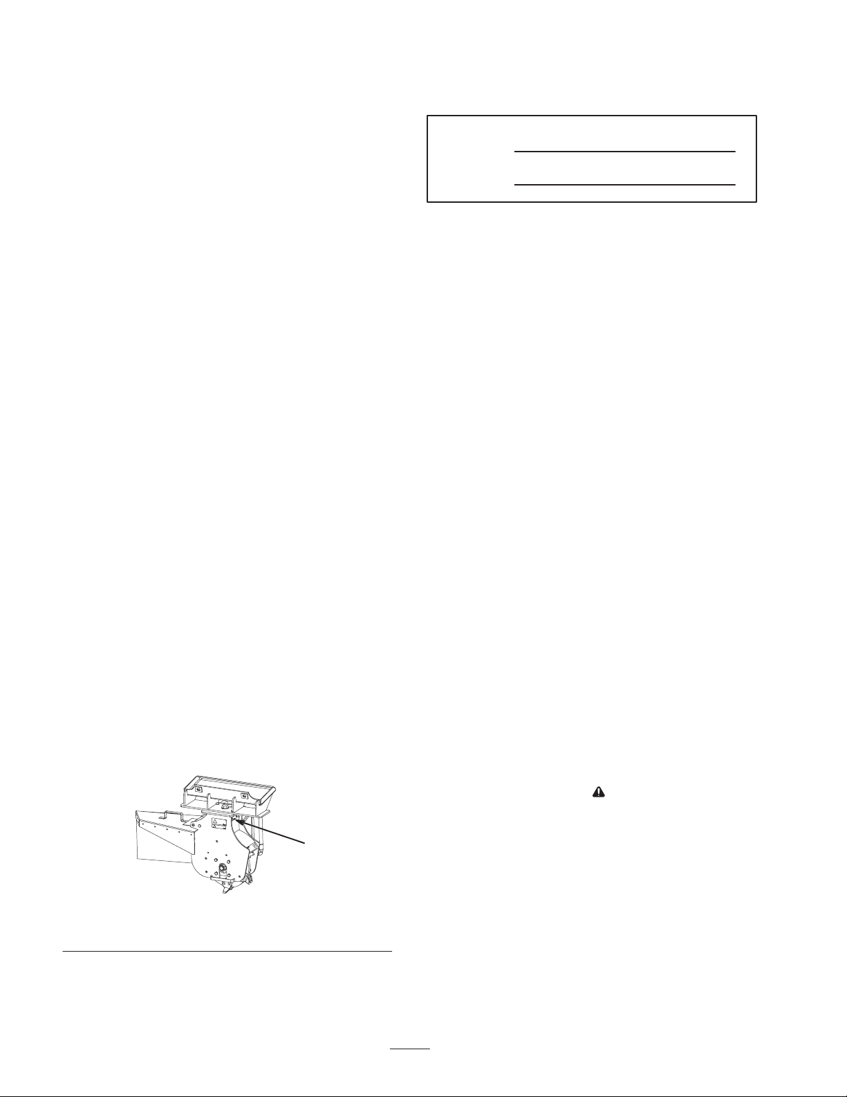
your specific product. You will find the model and serial
number plate at the location shown in Figure 1.
1
For your convenience, write the product model and serial
numbers in the space below.
Model No:
Serial No.
Read this manual carefully to learn how to operate and
maintain your product correctly. Reading this manual will
help you and others avoid personal injury and damage to
the product. Although we design, produce and market
safe, state-of-the-art products, you are responsible for
using the product properly and safely. You are also
responsible for training persons, who you allow to use the
product, about safe operation.
The warning system in this manual identifies potential
hazards and has special safety messages that help you and
others avoid personal injury, even death. Danger,
Warning, and Caution are signal words used to identify
the level of hazard. However, regardless of the hazard, be
extremely careful.
Danger signals an extreme hazard that will cause serious
injury or death if the recommended precautions are not
followed.
Warning signals a hazard that may cause serious injury or
death if the recommended precautions are not followed.
Caution signals a hazard that may cause minor or
moderate injury if the recommended precautions are not
followed.
Two other words are also used to highlight information.
Important calls attention to special mechanical
information, and Note emphasizes general information
worthy of special attention.
Safety
Improper use or maintenance by the operator or owner
can result in injury. To reduce the potential for injury,
comply with these safety instructions and always pay
attention to the safety alert symbol, which means
CAUTION, WARNING, or DANGER—“personal
safety instruction.” Failure to comply with the
instruction may result in personal injury or death.
Figure 1
1. Model and serial number plate
W 2005 by The Toro Company
8111 Lyndale Avenue South
Bloomington, MN 55420-1196
Contact us at www.Toro.com
All Rights Reserved
2
Printed in the USA
Page 3

Danger
Warning
The stump grinder is solely designed and tested
for use grinding stumps less than 36 in. (91 cm)
tall. Any other uses may cause a hazardous
situation resulting in injury or death to you or
bystanders.
Only use the stump grinder for grinding stumps
less than 36 in. (91 m) tall.
Danger
If you grind roots around buried power, gas,
and/or telephone lines, you may cut them causing
shock or explosion.
Have the property or work area marked for
buried lines and do not grind roots in marked
areas.
Danger
The moving teeth will severely cut hands, feet, or
other body parts.
• Keep hands, feet, and any other parts of your
body or clothing away from moving teeth.
• Before adjusting, cleaning, repairing, or
inspecting the stump grinder, lower it to the
ground, stop the engine, wait for all moving
parts to stop, and remove the ignition key.
During operation, debris will fly in all directions
and can cause injury to eyes and other exposed
body parts.
• Never operate the stump grinder without the
shield installed on the traction unit and the chip
guard on the grinder.
• Wear personal protective gear during
operation.
• Keep all bystanders at least 30 feet (9 m) away
from the work area.
Warning
If you do not fully seat the quick attach pins
through the attachment mount plate, the
attachment could fall off of the traction unit,
crushing you or bystanders.
• Ensure that your quick attach pins are fully
seated in the attachment mounting plate.
• Ensure that the attachment mounting plate is
free of any dirt or debris that may hinder the
connection of the traction unit to the
attachment.
• Refer to your traction unit Operator’s Manual
for detailed information on safely connecting an
attachment to your traction unit.
Warning
Warning
The loader arms may lower when in the raised
position after stopping the engine, crushing
anyone under them.
Lower the loader arms before stopping the engine.
Hydraulic fluid escaping under pressure can
penetrate skin and cause injury. Fluid injected
into the skin must be surgically removed within a
few hours by a doctor familiar with this form of
injury or gangrene may result.
• Keep your body and hands away from pin hole
leaks or nozzles that eject high pressure
hydraulic fluid.
• Use cardboard or paper to find hydraulic leaks,
never use your hands.
3
Page 4
Caution
Hydraulic couplers, hydraulic lines/valves, and
hydraulic fluid may be hot. If you contact hot
components you may be burned.
• Wear gloves when operating the hydraulic
couplers.
• Allow the traction unit to cool before touching
hydraulic components.
• Do not touch hydraulic fluid spills.
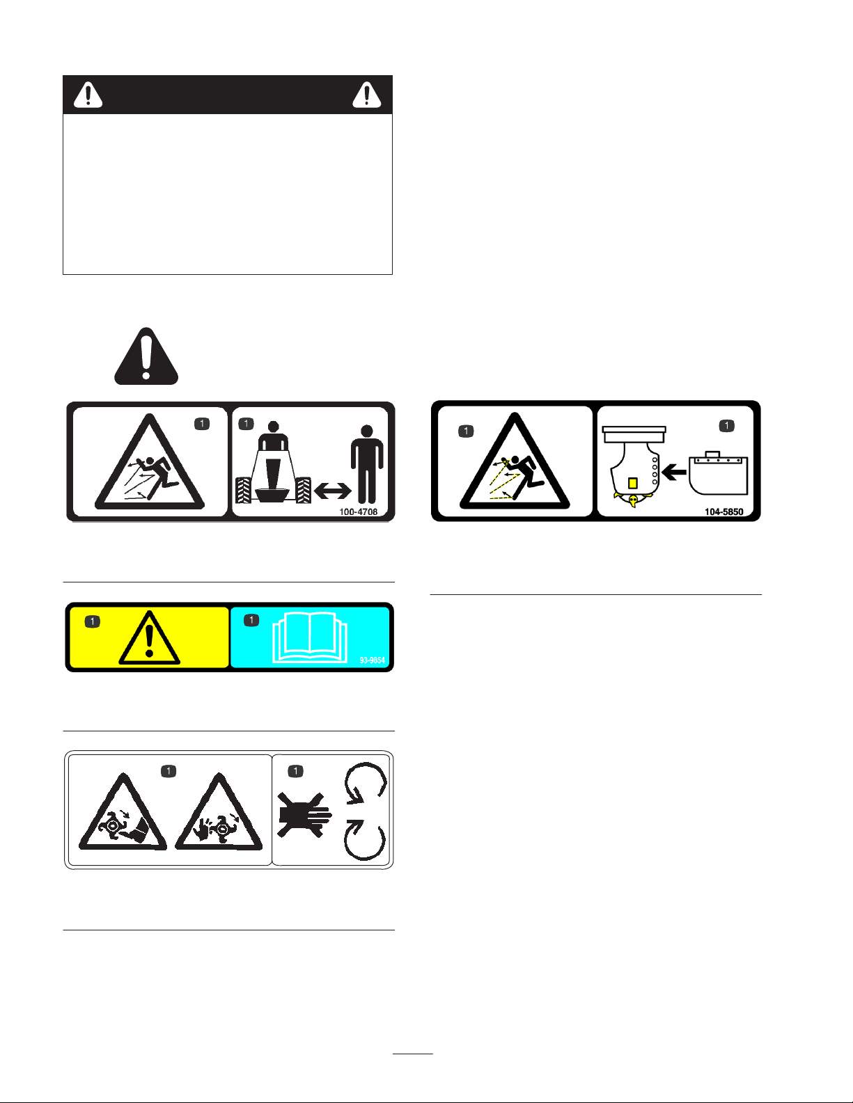
Safety Decals
Safety decals and instructions are easily visible to the operator and are located near any
area of potential danger. Replace any decal that is damaged or lost.
100-4708
1. Thrown object hazard—keep bystanders away
93-9854
1. Warning—read the Operator’s Manual before operating
93-7321
1. Cutting hazard, foot and hand—keep away from moving parts
104-5850
1. Thrown object hazard—do not operate without the chip guard
properly installed
4
Page 5

Specifications
Width with chip guard 44 in. (112 cm)
Width without chip guard 26 in. (66 cm)
Length 20 in. (51 cm)
Height 31 in. (79 cm)
Weight 265 lb. (120 kg)
Stability Ratings
To determine the degree of slope you can traverse with the
stump grinder installed on a traction unit, find the stability
rating for the hill position you want to travel in the
following table, then find the degree of slope for the same
rating and hill position in the Stability Data section of the
traction unit Operator’s Manual.
Orientation Stability Rating
Wheel speed 2000 RPM
Tooth tip speed 148 ft./s (45 m/s)
Number of teeth 12
Wheel diameter without
teeth
Wheel diameter with teeth 17 in. (43 cm)
Maximum height 36 in. (91 cm)
Maximum depth below grade 21 in. (53 cm)
Wheel index 0 or 30 degrees
Chip guard vertical
adjustment
Wheel stopping time Less than 5 seconds
13.4 in. (34 cm)
6 in. (15 cm)
Front Uphill
D
Rear Uphill
C
Side Uphill
C
Warning
If you exceed the maximum slope, the traction
unit could tip, possibly crushing you or
bystanders.
Do not drive the traction unit on a slope steeper
than the maximum recommended slope.
Important If you have a traction unit other than the
TX compact utility loader, do not use the rear
counterweight with the stump grinder. If you use the
counterweight, the traction unit will be less stable in the
front and side uphill positions.
5
Page 6

Installation
Refer to your traction unit Operator’s Manual for complete instructions on installing attachments onto the traction unit and
connecting hydraulic hoses.
Loose Parts
DESCRIPTION QTY. USE
Shield bracket, right
Shield bracket, left
Self-tapping screw, 5/16 x 3/4 in. (200/300
series traction units use only two screws)
Shield support
Shield
Skirt
Bolt, 1/4 x 1-1/2 in.
Washer
Locknut, 1/4 in.
TX bracket mounting template
Stump grinder
Chip guard
Guard pin
Hairpin cotter
Assembling the Operator
Shield
1
1
4
2
1
1
6
6
6
1
1
1
1
1
Assemble the operator shield
Install the chip guard
1
Installing the Shield Bracket on a 200 or
300 Series Traction Unit
1. Insert the tab on the shield bracket into the lift point
hole on the traction unit, with the hole in the bracket
aligning with the small hole in the traction unit frame
(Fig. 2).
Note: There is a right and left bracket. Ensure that
you install the correct bracket on each side. The tab
should be in the lift point hole and the bracket should
be on the outside of the frame (Fig. 2).
2
3
Figure 2
1. Shield bracket
2. Lift point hole
2. Secure the bracket to the frame with a self-tapping
screw (Fig. 2).
3. Repeat steps 1 and 2 for the other side of the traction
unit.
6
3. Tab
4. Self-tapping screw
4
m–5267
Page 7

Installing the Shield Bracket on a TX
Traction Unit
1. Measure in from the edges of the frame as illustrated
in Figure 3 and mark the locations of the holes for
mounting the shield bracket.
Note: If the holes exist, skip to step 3.
1.8 in.
(4.57 cm)
1
0.56 in.
(1.42 cm)
1.8 in.
(4.57 cm)
2
3
m–5277
Figure 4
1. Shield bracket 2. Self-tapping screw
4. Secure the bracket to the frame with 2 self-tapping
screws as illustrated in Figure 4.
5. Repeat steps 1 through 4 for the other side of the
traction unit.
Assembling the Shield
1
Figure 3
1. Mounting holes
2. Drill a hole (5/16 in. dia.) through the frame at each
marked location.
3. Align the tab on the shield bracket with the front edge
of the frame with the bracket inside of the loader arm
pocket (Fig. 4).
Note: There is a right and left bracket. Ensure that
you install the correct bracket on each side. The tab
should be over the frame edge and the bracket should
be inside the loader arm pocket with the 2 smaller
holes in the bracket lined up with the holes you drilled
in the frame (Fig. 4).
1. Slide the shield supports into the pockets in the shield
brackets on the traction unit (Fig. 5).
2. Assemble the shield and flexible skirt to the shield
supports as illustrated in Figure 5, using 6 bolts (1/4 x
1-1/2 in.), washers, and locknuts (1/4 in.).
Note: The skirt should drape over the engine or hood.
7
Page 8

3
7
5
6
5
3
4
4
1
m–5266
Figure 5
1. Shield support
2. Shield bracket
3. Shield
4. Skirt
5. Bolt, 1/4 x 1-1/2 in.
6. Washer
7. Locknut, 1/4 in.
Note: Install or remove the shield as needed by sliding it
into the brackets or pulling it out of the brackets. Do not
remove the brackets from the traction unit. You can
remove the shield easily by flexing it in the center as you
pull it out of the brackets.
Installing the Chip Guard
The stump grinder has 4 sets of mounting holes for
positioning the chip guard (Fig. 6). Move the guard up
(upper holes) when you are grinding close to the ground
and down (lower holes) when you are chipping tall
stumps. Install the chip guard as follows:
1. Position the mounting tube on the guard between two
holes on the grinder (Fig. 6).
2
m–5265
1
2
Figure 6
1. Mounting holes
2. Chip guard
3. Mounting tube
4. Guard pin
5. Hairpin cotter
2. Slide the guard pin through the holes in the grinder
and the mounting tube (Fig. 6).
3. Secure the pin with a hairpin cotter (Fig. 6).
Operation
Warning
During operation, debris will fly in all directions
and can cause injury to eyes and other exposed
body parts.
• Never operate the stump grinder without the
shield installed on the traction unit and the chip
guard on the grinder.
• Wear personal protective gear during
operation.
• Keep all bystanders at least 30 feet (9 m) away
from the work area.
Important Always use the traction unit to lift and
move the attachment.
8
Page 9

Grinding Stumps
1. If your traction unit has a speed selector, set it to the
slow (turtle position).
2. Start the engine.
3. Pull the auxiliary hydraulics lever to the operator grip
to engage the stump grinder.
4. Position the grinder on the left side and behind the
stump (Fig. 7).
5. Swing the grinder toward you using the attachment tilt
lever, grinding at a depth of 1/4 to 2 in. (0.5 to 5 cm),
depending on the hardness of the wood (Fig. 7).
Note: If you take too deep of a cut, the grinder will stall.
If it stalls, raise it slightly and try again.
6. Swing the grinder back out (Fig. 7), lower it 1/4 to 2
in. (0.5 to 5 cm) and repeat steps 4 through 6 until you
have ground down a few inches.
7. Raise the loader arms to the original height.
8. Move the grinder to the right (Fig. 7).
9. Repeat steps 4 through 8 until you reach the right side
of the stump.
m–5275
Figure 7
10. Return the grinder to the left side of the stump, lower
it, and repeat steps 3 through 10 until you have ground
the stump into the ground.
Note: To contain the chips, you may need to stop the
grinder and move the chip guard up as you move the
grinder down.
11. When finished, stop the grinder by moving the
auxiliary hydraulics lever into neutral.
Grinding Roots
1. Stop the grinder and hang it vertically from the loader
arms a few inches off of the ground.
2. Stop the engine and remove the key.
9
Page 10

3. Loosen the large bolt on the top of the grinder (Fig. 8).
2
1
11. When finished, stop the grinder by moving the
auxiliary hydraulics lever into neutral.
12. Loosen the large bolt on the top of the grinder (Fig. 8).
13. Remove the front bolt and nut securing the grinder
(Fig. 8).
14. Swing the grinder 30 degrees counter-clockwise
(Fig. 8).
15. Torque the large bolt on top of the grinder to 300 ft.-lb.
(406 N⋅m) (Fig. 8)
16. Install the bolt and nut in the front hole and torque
them to 75 ft.-lb. (101 N⋅m) (Fig. 8).
Tips for Grinding
• Always use full throttle (maximum engine speed).
m–5273
Figure 8
1. Large bolt—loosen 2. Front bolt—remove
4. Remove the front bolt and nut securing the grinder
(Fig. 8).
5. Swing the grinder 30 degrees clockwise (Fig. 8).
6. Torque the large bolt on top of the grinder to 300 ft.-lb.
(406 N⋅m) (Fig. 8)
7. Install the bolt and nut in the front hole and torque
them to 75 ft.-lb. (101 N⋅m) (Fig. 8).
8. Start the traction unit and start the grinder.
9. Lower the grinder into the root.
10. Move the grinder along the length of the root by
moving the traction unit over the root.
Maintenance
• Never transport the stump grinder with the loader arms
raised. Keep the arms lowered and the grinder tilted
up.
• On 200 and 300 series traction units set the speed
selector to the slow (turtle position) and the flow
divider to approximately the 10 o’clock position.
Transporting the Stump
Grinder on a Trailer
• Place the stump grinder on a trailer or truck capable of
carrying it.
• Securely tie the grinder to the trailer or truck using tie
straps appropriate for the weight of the grinder and for
highway use.
• Remove the operator’s shield from the traction unit
before transporting the traction unit or the shield may
be damaged in transport.
Recommended Maintenance Schedule
Maintenance Service
Interval
8 hours
Storage Service
Maintenance Procedure
• Grease all fittings.
• Check the teeth and replace any that are worn or damaged.
• Ensure that the disk stops within 5 seconds of releasing the auxiliary hydraulics
lever. If not, contact your Authorized Toro Dealer for brake service.
• Grease all fittings.
• Paint chipped surfaces
10
Page 11

Caution
If you leave the key in the ignition switch, someone could accidently start the engine and
seriously injure you or other bystanders.
Remove the key from the ignition and disconnect the wire from the spark plug before you do
any maintenance. Set the wire aside so that it does not accidentally contact the spark plug.
Greasing the Stump Grinder
Grease all pivot joints every 8 operating hours and
immediately after every washing.
Grease Type: General-purpose grease.
1. Clean the grease fittings with a rag.
2. Connect a grease gun to each fitting
(Fig 9).
m–5276
Figure 9
3. Pump grease into the fittings until grease begins to
ooze out of the bearings (approximately 3 pumps).
4. Wipe up any excess grease.
3. Manually rotate the grinding wheel until you can
access the teeth you want to replace (Fig. 10).
3
1
4
2
Figure 10
1. Straight teeth
2. Curved teeth
3. Bolt
4. Disk
m–5274
Replacing the Teeth
Due to the high amount of wear placed on the teeth, you
will need to replace them periodically. There are two
types of teeth, curved and straight. The teeth are mounted
on the wheel in pairs, alternating between curved and
straight. Each pair contains a right and a left version of
the tooth. Always replace the teeth in pairs (2 curved or 2
straight together). Always replace teeth with the same
type of tooth (curved or straight).
In each pair, one tooth has two counter sunk holes through
it; the other has two threaded holes. Mount the teeth
facing the same direction as the teeth you removed.
To replace a pair of teeth, complete the following
procedure:
1. Disconnect the stump grinder from the traction unit.
2. Connect the stump grinder hydraulic connectors
together.
4. Remove the two bolts securing the teeth and discard
the teeth (Fig. 10).
5. Install the new teeth on the disc in the same location
and orientation as the teeth you removed using the
existing mounting bolts (Fig. 10).
Note: The location on the disk for curved teeth is
marked by an indent ground into the disk between the
tooth mounting holes. Straight tooth locations do not
have this indent.
6. Torque the bolts securing the teeth to 240 ft.-lb.
(325 N⋅m).
Storage
1. Before long term storage, brush the dirt from the
attachment. Do not wash it, because washing will
cause rust.
2. Check the condition of the teeth. Replace any worn or
damaged teeth.
11
Page 12

3. Grease all fittings.
gpgg
g
4. Check and tighten all bolts, nuts, and screws. Repair or
replace any part that is damaged or worn.
6. Paint all scratched or bare metal surfaces. Paint is
available from your Authorized Service Dealer.
7. Store the grinder in a clean, dry garage or storage area.
5. Ensure that all hydraulic couplers are connected
together to prevent contamination of the hydraulic
system.
Troubleshooting
Problem Possible Causes Corrective Action
Cutting disk stops during cutting.
Cutting disk does not turn.
1. Too deep of a cut 1. Raise the loader arms 1/2 in.
2. Teeth worn, damaged, or
broken.
1. Hydraulic coupler not
completely connected
2. Damaged hydraulic coupler 2. Check/replace couplers
3. A hydraulic hose is kinked,
pinched, or obstructed
4. Auxiliary valve on the traction
unit is not opening.
5. Hydraulic motor failure 5. Contact Authorized Service
8. Cover the grinder to protect it and keep it clean.
2. Replace any worn, damaged,
or broken teeth.
1. Check and tighten all couplers.
3. Find and remove the kink,
pinch, or obstruction.
4. Repair the valve.
Dealer.
Does not cut fast enough.
Cutting disk turns in the wrong
direction
1. Worn teeth 1. Replace any worn teeth.
2. Wrong setting on flow divider
and speed lever
3. Quick coupler or hose
restriction
4. Hydraulic system too hot 4. Shutdown and allow the
5. Relief valve set below
specifications
1. Auxiliary valve lever in wrong
position
2. Hydraulic hoses reversed 2. Disconnect hoses and switch
2. Set the flow divider to the 10:00
position and the speed lever to
the turtle position.
3. Check hoses and couplers and
repair any problems found.
system to cool.
5. Contact Authorized Service
Dealer.
1. Move auxiliary valve lever to
the rearward position.
connectors.
12
 Loading...