

Page 1
FORM NO. 3322–648
Multi-Purpose
T
ool
Sitework Systems Attachment
Model No. 22423 – 890001 & Up
Operator’s Manual
English (CE)
Page 2
Contents
Page
Introduction 2.
Safety 2
Safety Decals3. . . . . . . . . . . . . . . . . . . . . . . . . . . . .
Specifications 3
Stability Ratings4. . . . . . . . . . . . . . . . . . . . . . . . . . .
Installation 5
Loose Parts5. . . . . . . . . . . . . . . . . . . . . . . . . . . . . . .
Installing the Frame on the T
Installing Accessories onto the Frame6. . . . . . . . . .
Removing the Frame from the T
Operation 7
Boom Jib Operation7. . . . . . . . . . . . . . . . . . . . . . . .
Scarifier/Ripper Operation7. . . . . . . . . . . . . . . . . . .
Hitch Operation7. . . . . . . . . . . . . . . . . . . . . . . . . . .
Maintenance 8
Service Interval Chart8. . . . . . . . . . . . . . . . . . . . . .
Replacing Scarifier T
Storage 8
. . . . . . . . . . . . . . . . . . . . . . . . . . . . . . . .
. . . . . . . . . . . . . . . . . . . . . . . . . . . . . . . . . . . . . .
. . . . . . . . . . . . . . . . . . . . . . . . . . . . . . . .
. . . . . . . . . . . . . . . . . . . . . . . . . . . . . . . . . .
raction Unit5. . . . . . .
raction Unit6. . . . .
. . . . . . . . . . . . . . . . . . . . . . . . . . . . . . . . . . .
. . . . . . . . . . . . . . . . . . . . . . . . . . . . . . . . .
eeth T
ips 8
. . . . . . . . . . . . . . . .
. . . . . . . . . . . . . . . . . . . . . . . . . . . . . . . . . .
Introduction
DANGER
serious injury or death if the recommended precautions
are not followed.
WARNING
or death if the recommended precautions are not followed.
CAUTION
moderate injury if the recommended precautions are not
followed.
wo other words are also used to highlight information.
T
“Important” calls attention to special mechanical
information and “Note” emphasizes general information
worthy of special attention.
The left and right side of the machine is determined by
sitting on the seat in the normal operator’s position.
signals an extreme hazard that will cause
signals a hazard that may cause serious injury
signals a hazard that may cause minor or
Safety
Impr
oper use or maintenance by the operator or owner
can r
esult in injury
comply with these safety instructions and those in the
traction unit operator’s manual. Always pay attention
to the safety alert
W
ARNING, or DANGER—“personal safety
instruction.” Failur
may r
esult in personal injury or death.
. T
o r
educe the potential for injury
symbol, which means CAUTION,
e to comply with the instruction
,
W
e want you to be completely satisfied with your new
product, so feel free to contact your local Authorized
Service Dealer for help with service, genuine replacement
parts, or other information you may require.
Whenever you contact your Dealer or the factory
know the model and serial numbers of your product.
These numbers will help the Dealer or Service
Representative provide information about your product.
Y
ou will find the model and serial number on a plate
located on the back of the frame.
For your convenience, write the product model and serial
numbers in the space below
Model No:
Serial No.
The
warning system in this manual identifies potential
hazards and has special safety messages that help you and
others avoid personal injury
W
ARNING and CAUTION are signal words used to
identify the level of hazard. However
hazard, be extremely careful.
.
, even death. DANGER,
, regardless of the
, always
DANGER
POTENTIAL HAZARD
• Ther
WHA
•
HOW T
•
e may be buried power
telephone lines in the work ar
T CAN HAPPEN
Shock or explosion may occur
O AVOID THE HAZARD
Have the pr
buried lines and do not dig in marked ar
operty or work ar
, gas, and/or
ea.
.
ea marked for
eas.
DANGER
POTENTIAL HAZARD
• Ther
WHA
•
HOW T
•
e may be overhead power lines in the work
area.
T CAN HAPPEN
Shock may occur if a power line is touched by a
tr
ee or other object that is being transported.
O AVOID THE HAZARD
Survey and mark the ar
overhead power line, and do not transport tr
or tall objects under the power lines.
ea wher
e ther
e ar
e
ees
The T
8111 Lyndale Ave. South
Bloomington, MN 55420–1196
oro Company
– 1999
2
All Rights Reserved
Printed in the USA
Page 3
WARNING
CAUTION
POTENTIAL HAZARD
•
When the engine is off, attachments in the
raised position can gradually lower
WHA
T CAN HAPPEN
•
Someone nearby may be pinned or injur
the attachment as it lowers.
HOW T
•
O AVOID THE HAZARD
Always lower the attachment lift each time you
shut off the traction unit.
.
ed by
WARNING
POTENTIAL HAZARD
•
When going up or down hill, the machine could
overturn if the heavy end is toward the
downhill side.
WHA
T CAN HAPPEN
•
Someone may be pinned or seriously injured by
the machine if it overturns.
HOW T
•
O AVOID THE HAZARD
Operate up and down slopes with the heavy end
of the machine uphill. Carrying a load with the
multi–purpose tool will make the fr
heavy.
ont end
POTENTIAL HAZARD
•
If you step off of the platform with the load
raised, the machine could tip forward.
WHA
T CAN HAPPEN
•
Someone nearby may be pinned or injur
HOW T
•
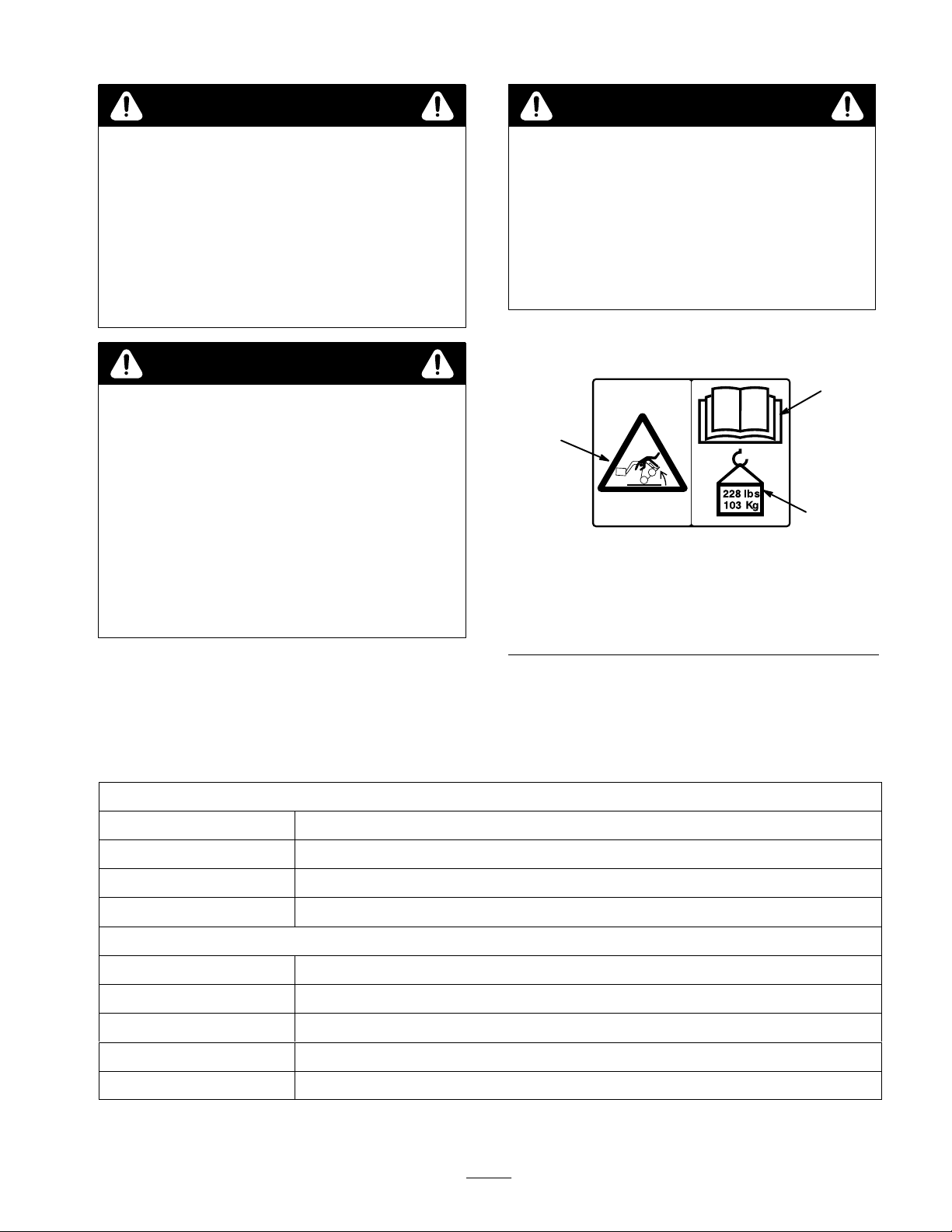
Safety
1. Machine
O AVOID THE HAZARD
Lower the load befor
platform.
Decals
1
roll-over–
exceeding rated load
capacity can cause
instability
e stepping off or the
#
99–9940
Figure 1
2.
Read operator’s manual
3.
Maximum load capacity
ed.
2
3
Specifications
Note:
Specifications and design are subject to change without notice.
Frame
Width 24 inches (61 cm)
Length
Height
Weight
Boom jib (1)
Width
Length
Height
Weight
Chain
4 inches (10 cm)
10 inches (25 cm)
40 lbs (18 Kg)
0.63 inches (1.6 cm)
32.4 inches (82.3 cm)
9.4 inches (23.9 cm)
23.2 lbs (10.5 Kg)
35 links, approximately 2.5 ft (76 cm), with S–hook ends
3
Page 4

Scarifier teeth (3)
Width (with tip)
Width (without tip)
Length
Height 1
W
eight (each)
Tips
Ball hitch (1, ball not included)
(Suitable for mounting balls with 1 inch (2.5 cm) diameter mounting studs)
Width
Length
Height
Weight
Stability
To
determine the degree of slope you can traverse with the
multi-purpose tool installed on a traction unit, find the
stability rating for the hill position you want to travel in
the appropriate table below, then find the degree of slope
for the same rating and hill position in the Stability Data
section of the traction unit operator’s manual.
Ratings
2.0 inches (5.1 cm)
0.63 inches (1.6 cm)
13.0 inches (13.0 cm)
1.7 inches (29.7 cm)
9.0 lbs (4.1 Kg)
Replaceable, cast iron spear points
3.0 inches (7.6 cm)
8.4 inches (21.3 cm)
9.4 inches (23.9 cm)
7.5 lbs (3.4 Kg)
Stability With a Loaded Boom Jib
Orientation
Front Uphill
Stability Rating
C
WARNING
POTENTIAL HAZARD
•
Exceeding the maximum slope can cause the
traction unit to tip.
WHA
T CAN HAPPEN
•
If the traction unit tips, you or bystanders could
be crushed.
HOW T
•
O AVOID THE HAZARD
Do not drive the the traction unit on a slope
steeper that the maximum slope.
Rear Uphill
D
Side Uphill
C
IMPORTANT:
jib installed is rated for use with the counterweight.
Do not use the boom jib without the counterweight or
the traction unit will become unstable.
The multi-purpose tool with the boom
4
Page 5

Stability With an Unloaded Boom Jib
Stability With the Scarifier Teeth
Orientation
Front Uphill
Stability Rating
E
Rear Uphill
B
Side Uphill
B
IMPORTANT:
jib installed is rated for use with the counterweight.
Do not use the boom jib without the counterweight or
the traction unit will become unstable.
The multi-purpose tool with the boom
Orientation
Front Uphill
Stability Rating
D
Rear Uphill
B
Side Uphill
C
Note:
The multi-purpose tool with the scarifier teeth
installed is rated for use without the counterweight. If you
use the counterweight, the traction unit will be less stable
in the front and side uphill positions.
Stability With the Hitch
Never
attempt to move a trailer on any slope. Because of
this, there are no stability ratings for the hitch. Always
use the counterweight when pulling trailers.
Installation
Loose
DESCRIPTION QTY. USE
Frame 1 Install
Boom jib
Lifting chain
Scarifier teeth
Hitch 1
Clevis pin
Hairpin cotter
Installing
T
raction Unit
Parts
the Frame on the
on traction unit
1
1
3
3
3
Install on frame
Install on frame
Install on frame
Secure boom jib, scarifier teeth, and hitch to
the frame
1.
Ensure that the frame is positioned on a level surface
with enough space behind it to accommodate the
traction unit.
IMPORTANT:
plates ar
e fr
ee of any dirt or debris.
Befor
e installing, ensur
e that the mount
2.
Move pump control lever to slow (turtle) position.
Start engine.
5
Page 6

3.
Slowly push the attachment tilt lever forward to tilt the
mount plate forward.
4.
Position mount plate into the upper lip of the receiver
plate on the frame (Fig. 2).
1
2
1
3
2
Figure
1. Mount
5. Raise
IMPORTANT
enough to clear the gr
be tilted all the way back.
6.
7.
1. Quick
plate
the loader arms while tilting back the mount
plate at the same time.
: The attachment should be raised
ound and the mount plate should
Stop the engine.
Engage the quick attach pins (Fig. 3).
1
Figure
attach pins (shown in engaged position)
2
2.
Receiver plate
m–4056
3
m–4055
4
Figure
1. Frame
2. Accessory
4. Repeat
Removing
T
raction Unit
1. Start
2.
3.
4.
steps 1 through 3 for the remaining accessory
positions if needed.
the Frame from the
the engine and lower the frame to the ground or
onto a trailer
Stop the engine.
Disengage the quick attach pins by turning them to the
outside.
Start the engine, tilt the mount plate forward, and back
the traction unit away from the frame.
.
4
3. Clevis
4.
Hairpin cotter”
pin
m–3929
Installing
Accessories onto the
Frame
All
accessories (scarifier teeth, boom jib, and hitch) are
installed into the slots in the frame in the same way
boom jib and hitch should always be installed in the
center position. The scarifier teeth can be installed in any
or all of the three positions (up to 3 teeth may be installed
at one time). Figure 4 illustrates a scarifier tooth being
installed.
Slide the slot on top of the accessory onto the top bar
1.
of one of the three accessory positions (Fig. 4).
2.
Swing the bottom of the accessory into the frame and
secure it with a clevis pin (Fig, 4).
3.
Secure the pin with a hairpin cotter (Fig. 4).
. The
6
Page 7

Operation
Scarifier/Ripper
Operation
The multi-purpose tool can be used in 3 dif
operating modes, as follows:
•
Boom jib (Fig. 5)
•
Scarifier/ripper (Fig. 6)
•
Hitch (Fig. 7)
Boom
Jib Operation
Figure
5
ferent
m–3943
m–3941
Figure
With
the scarifier teeth installed, the multi-purpose tool
can be used to loosen hard packed ground. Lower the
teeth to the ground by lowering the attachment arms and
tilting the attachment plate forward. Move the traction
unit slowly backward while lowering the teeth into the
ground. Several shallow passes may be necessary to
thoroughly break up the ground.
The teeth can also be used to hook and tear out bushes and
roots. It is also useful for raking up debris and brush.
6
With
the boom jib installed, the multi-purpose tool can be
used to lift and transport various items, such as balled
trees. Secure the item being lifted as close as possible to
the boom jib frame using the provided lifting chain.
Always use the lifting chain provided to secure items to
the boom jib.
Never lift more than the rated lift capacity of the traction
unit. When transporting a load, keep it as close to the
ground as possible.
The counterweight attachment is required when using the
boom jib.
WARNING
POTENTIAL HAZARD
•
Pulling tr
the chain.
WHA
•
The chain could break and snap back, causing
serious injury
HOW T
•
Do not attempt to pull tr
large objects with the boom jib.
ee stumps and other items can weaken
T CAN HAPPEN
.
O AVOID THE HAZARD
ee stumps and other
Hitch
With
used to move trailers. Y
proper size for your trailer
without a ball to tow trailers with hitches that require a
pin for attachment.
Never attach a trailer to the hitch that has a tongue weight
greater than the rated lift capacity of the traction unit.
Never try to move a trailer on a slope.
Operation
Figure
the hitch installed, the multi-purpose tool can be
ou can install a ball hitch of
7
, or you can use the hitch
m–3942
The counterweight attachment is required when using the
hitch to move trailers.
7
Page 8

When crossing on or near a public road or street, always
follow traf
pertaining to slow moving vehicles. The traction unit and
accessories are not designed for use on public roads or
streets.
fic laws and regulations, especially those
Maintenance
WARNING
POTENTIAL HAZARD
•
Pulling trailers or other objects using a r
chain or cable can cause the r
cable to br
WHA
T CAN HAPPEN
•
The r
back, causing serious injury
HOW T
•
Do not attempt to pull trailers or other objects
with a r
eak under tension.
ope, chain, or cable could break and snap
O AVOID THE HAZARD
ope, chain, or cable.
ope, chain, or
.
ope,
Service
Service
Scarifier teeth tips–inspect
Chipped surfaces—paint
Replacing
Inspect
damage or wear
follows:
Remove the roll pin securing the tip to the end of the
1.
scarifier tooth and remove the tip.
2.
Install a new tip onto the end of the scarifier tooth and
secure it with the roll pin.
Interval Chart
Operation
POTENTIAL
•
If you leave the key in the ignition switch, someone could start the engine.
WHA
T CAN HAPPEN
•
Accidental starting of the engine could seriously injur
HOW T
•
Remove the key fr
the scarifier teeth tips every 25 operating hours for
. Replace any damaged or worn tips, as
HAZARD
O AVOID THE HAZARD
om the ignition switch befor
Scarifier T
eeth T
Each
Use5Hours25Hours
e you or other bystanders.
e you do any maintenance.
ips
Storage
1.
Before long term storage, wash the attachment with
mild deter
2.
Paint all scratched or bare metal surfaces. Paint is
available from your Authorized Service Dealer
Store the attachment in a clean, dry garage or storage
3.
area. Cover it to protect it and keep it clean.
200
Hours
X X
gent and water to remove dirt and grime.
Storage
Service
Replace if damaged
X
Notes
or worn
.
8
 Loading...