

Page 1

Broom
Sitework Systems Attachment
Model No. 22415—990001 & Up
Form No. 3323-263
Operator’s Manual
English (CE)
Page 2

Contents
Page
Introduction 2.
Safety 2
Safety Decals3. . . . . . . . . . . . . . . . . . . . . . . . . . . . .
Specifications 3
Stability Ratings4. . . . . . . . . . . . . . . . . . . . . . . . . . .
Installation 5
Loose Parts5. . . . . . . . . . . . . . . . . . . . . . . . . . . . . . .
Assembling the Broom5. . . . . . . . . . . . . . . . . . . . . .
Greasing the Broom6. . . . . . . . . . . . . . . . . . . . . . . .
Checking Castor T
Installing the Broom on the T
Connecting the Hydraulic Hoses8. . . . . . . . . . . . . .
Removing the Broom from the Traction Unit8. . . .
Adjusting the Downward Pressure of the Broom8.
Operation 9
T
ips for Sweeping9. . . . . . . . . . . . . . . . . . . . . . . . .
Maintenance 10
Service Interval Chart10. . . . . . . . . . . . . . . . . . . . . .
Greasing and Lubrication10. . . . . . . . . . . . . . . . . . . .
Changing Brushes12. . . . . . . . . . . . . . . . . . . . . . . . .
Replacing the Castor Fork Bushings12. . . . . . . . . . .
Servicing a Castor Wheel13. . . . . . . . . . . . . . . . . . . .
Storage 13
Troubleshooting 14
. . . . . . . . . . . . . . . . . . . . . . . . . . . . . . . .
. . . . . . . . . . . . . . . . . . . . . . . . . . . . . . . . . . . . . .
. . . . . . . . . . . . . . . . . . . . . . . . . . . . . . . .
. . . . . . . . . . . . . . . . . . . . . . . . . . . . . . . . . .
ire Pressure6. . . . . . . . . . . . . . . .
raction Unit6. . . . . . .
. . . . . . . . . . . . . . . . . . . . . . . . . . . . . . . . . . .
. . . . . . . . . . . . . . . . . . . . . . . . . . . . . . . . .
. . . . . . . . . . . . . . . . . . . . . . . . . . . . . . . . . .
. . . . . . . . . . . . . . . . . . . . . . . . . . . . . .
Model No:
Serial No.
The
warning system in this manual identifies potential
hazards and has special safety messages that help you and
others avoid personal injury
W
ARNING and CAUTION are signal words used to
identify the level of hazard. However
hazard, be extremely careful.
DANGER
serious injury or death if the recommended precautions
are not followed.
WARNING
or death if the recommended precautions are not followed.
CAUTION
moderate injury if the recommended precautions are not
followed.
wo other words are also used to highlight information.
T
“Important” calls attention to special mechanical
information and “Note” emphasizes general information
worthy of special attention.
The left and right side of the machine is determined by
standing in the normal operator’s position.
signals an extreme hazard that will cause
signals a hazard that may cause serious injury
signals a hazard that may cause minor or
, even death. DANGER,
, regardless of the
Safety
Introduction
W
e want you to be completely satisfied with your new
product, so feel free to contact your local Authorized
Service Dealer for help with service, genuine replacement
parts, or other information you may require.
Whenever you contact your Authorized Service Dealer or
the factory
your product. These numbers will help the Service Dealer
or Service Representative provide exact information about
your specific product. Y
number on a plate located on the product. For your
convenience, write the product model and serial numbers
in the space below
, always know the model and serial numbers of
ou will find the model and serial
.
Impr
oper use or maintenance by the operator or owner
can r
esult in injury
comply with the safety instructions in the traction unit
operator’
safety alert
W
ARNING, or DANGER—“personal safety
instruction.” Failur
may r
s manual and always pay attention to the
esult in personal injury or death.
. T
o r
educe the potential for injury
symbol, which means CAUTION,
e to comply with the instruction
,
The Toro Company – 1999
8111 Lyndale Ave. South
Bloomington, MN 55420–1196
2
All Rights Reserved
Printed in the USA
Page 3
WARNING
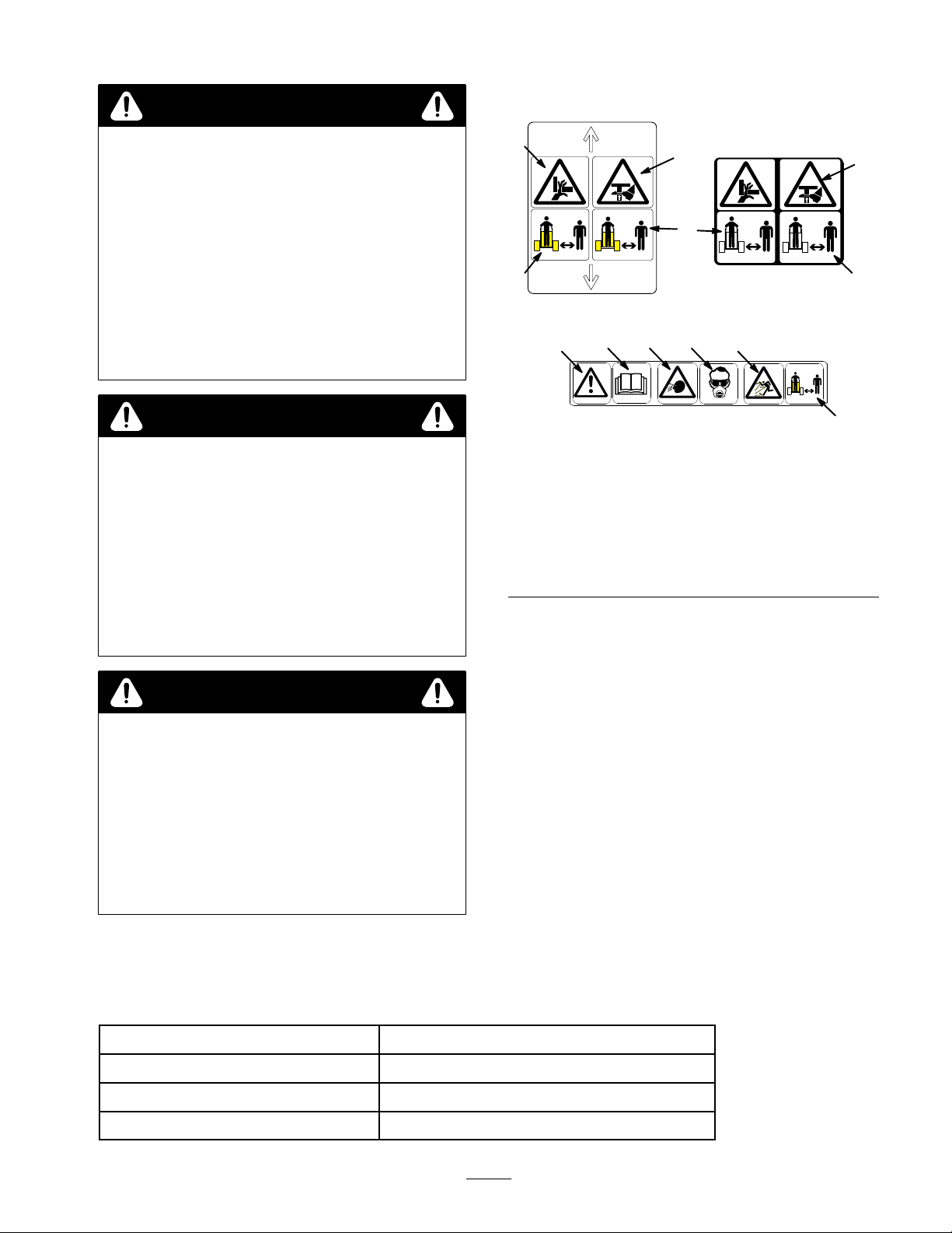
Safety
Decals
POTENTIAL HAZARD
•
Contact with r
WHA
T CAN HAPPEN
•
Rotating bristles can injur
body parts.
HOW T
•
• Befor
O AVOID THE HAZARD
Keep your hands, feet, and any other part of
your body or clothing away fr
parts.
e adjusting, cleaning, repairing and
inspecting the br
gr
ound and stop the engine. Remove the key
otating bristles may cause injury
e hands, feet or other
om r
otating
oom, lower the br
oom to the
WARNING
POTENTIAL HAZARD
•
Small stones, dirt clumps, or other debris may
be thr
own during sweeping.
WHA
T CAN HAPPEN
•
Serious injury may r
HOW T
•
•
O AVOID THE HAZARD
Keep childr
area.
Always wear safety glasses or goggles when
operating the br
en and bystanders out of the work
esult.
oom.
1
.
3
# 100–4652
5 6 7
.
4
1. Pinching/crushing
hazard—hand
2. Pinching/crushing
hazard—foot
3. Keep
4.
5.
bystanders away
Safety alert symbol
Read operator’s manual
2
3
8
# 100–4654
Figure 1
6.
7. W
8.
#
100–4650
Thrown object
hazard—face
ear eye and breathing
protection
Thrown object
hazard—whole body
2
3
3
WARNING
POTENTIAL HAZARD
•
When the engine is off, attachments in the
raised position can gradually lower
WHA
T CAN HAPPEN
•
Someone nearby may be pinned or injur
the attachment as it lowers.
HOW T
•
O AVOID THE HAZARD
Always lower the attachment lift each time you
shut off the traction unit.
.
ed by
Specifications
Note:
Specifications and design are subject to change without notice.
Width 53
Length
Height
Weight
inches (135 cm)
40 inches (102 cm)
50 inches (127 cm)
476 lbs (216 Kg)
3
Page 4

Maximum swing angle
Sweeping width
with no swing rotation
With 25 degree swing rotation
Broom diameter 24 inches (51 cm)
25 degrees
48 inches (122 cm)
42 inches (106.6 cm)
Number of brushes
Brush material
Brush rotation speed
Hydraulic drive
Castor wheels
Stability
To
determine the degree of slope you can traverse with the
broom installed on a traction unit, find the stability rating
for the hill position you want to travel in the table below
then find the degree of slope for the same rating and hill
position in the Stability Data section of the traction unit
operator’
Orientation
Front Uphill
Ratings
s manual.
Stability Rating
27
Polypropylene and/or steel
150 rpm
Direct drive, 1
T
wo 8.5 in. (21.5 cm) x 3.5 in. (8.9) pneumatic
tires
C
1.9 cu. in. (195 cc) geroler motor
,
POTENTIAL HAZARD
•
Exceeding the maximum r
can cause the traction unit to tip.
WHA
T CAN HAPPEN
•
If the traction unit tips, you or bystanders could
be crushed.
HOW T
•
O AVOID THE HAZARD
Do not drive the traction unit on a slope steeper
than the maximum r
determined in the pr
traction unit operator’s manual.
WARNING
ecommended slope
ecommended slope, as
evious table and the
Rear Uphill
C
Side Uphill
C
Note:
On traction units with a rear operator platform, the
broom is rated for use without the counterweight. If you
use the counterweight with the broom, the traction unit
will be less stable in the front and side uphill positions.
4
Page 5
Installation
Loose
Note:
Parts
Use the chart below to identify parts for assembly
DESCRIPTION
Pivot frame
Broom head
Attachment frame
Swing arm
Bolt, 3/4 in. (1.9 cm) x 10 1/2 in. (26.7 cm)
Nut, 3/4 in. (1.9 cm)
Thrust washer, large
Pivot cap
Bolt, 3/4 in. (1.9 cm) x 4 in. (10 cm)
Spacer
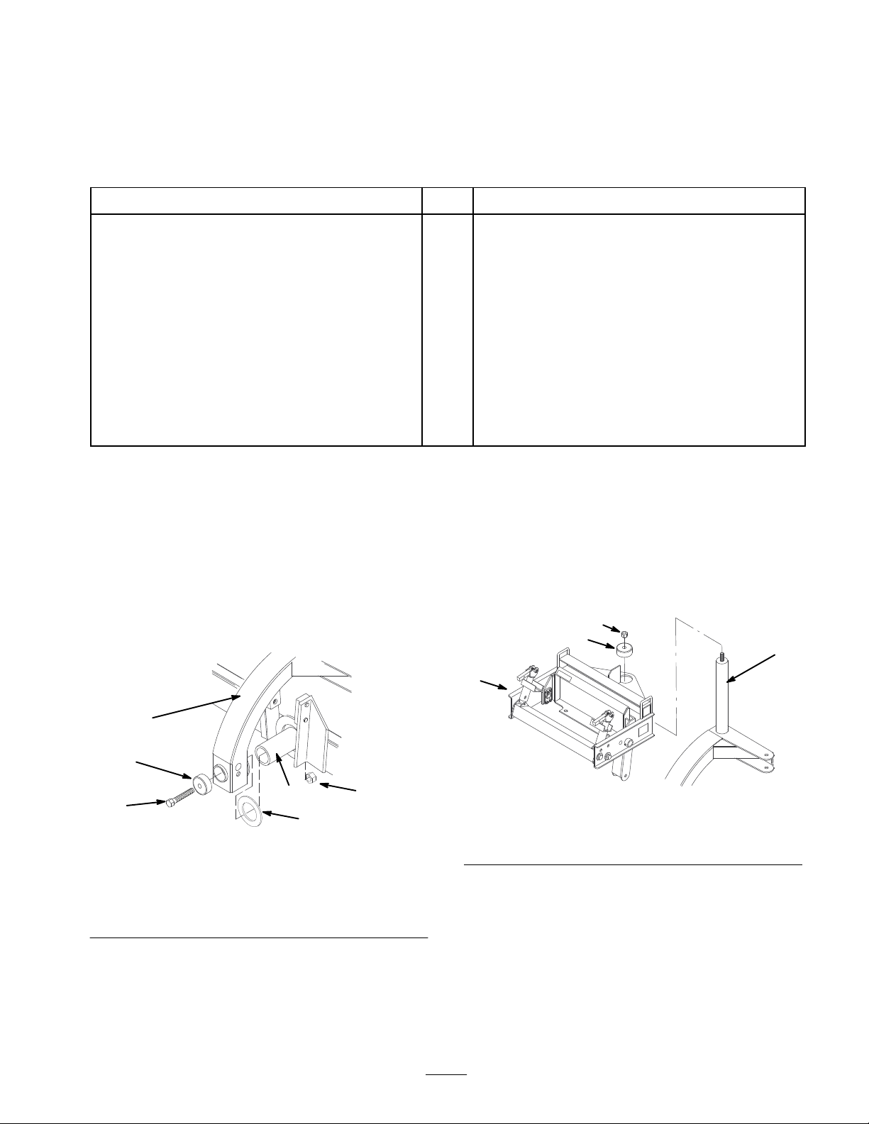
Assembling
1. Slide
the thrust washer and the pivot frame onto the
the Broom
shaft on the back of the broom head (Fig. 2)
2.
Secure the pivot frame with a pivot cap, 3/4 in.
(1.9 cm) x 10 1/2 in. (26.7 cm) bolt, and 3/4 in.
(1.9 cm) nut (Fig. 2).
Note:
Ensure that the pivot frame rotates around the shaft.
If it cannot, the bolt and nut are too tight.
.
QTY. USE
1
1
1
1
1
Assemble broom
4
1
2
2
4
3. Lubricate
the shaft on the top of the pivot frame
(Fig. 3) with a corrosion resistant, calcium-sulphonate
based grease.
4.
Slide the attachment frame onto the shaft on the top of
the pivot frame (Fig. 3).
5.
Secure the attachment frame with a pivot cap and
3/4 in. (1.9 cm) nut (Fig. 3).
4
3
2
3
5
1. Pivot
2. Shaft
3.
Pivot cap
4.
Thrust washer
1
frame
Figure
2
4
2
5.
Bolt, 3/4 in. (1.9 cm) x
10 1/2 in. (26.7 cm)
6.
Nut, 3/4 in. (1.9 cm)
1
6
m–4176
m–4175
Figure
1. Assembly
2. Shaft
6. Torque
7.
Connect the swing arm to the swing bracket on the
frame
the nut to 265 ft·lbs (359 Nm).
3
Pivot cap
3.
4.
Nut, 3/4 in. (1.9 cm)
pivot frame with two spacers, a 3/4 in. (1.9 cm) x 4 in.
(10 cm) bolt, and a 3/4 in. (1.9 cm) nut (Fig. 4).
T
orque to 265 ft·lbs (359 Nm).
5
Page 6

8.
Route the hydraulic hoses through the ring on the back
of the pivot frame (Fig. 4)
6
5
2
5
4
m–4077
Installing
T
raction Unit
the Broom on the
3
IMPORTANT:
machine, make sur
1
or debris.
1.
Position the broom on a level surface with enough
Befor
e connecting any attachments to
e mount plates ar
e fr
ee of any dirt
space behind it to accommodate the traction unit.
2.
Start the engine.
3. T
ilt the attachment mount plate forward.
4.
Lift the loader arms so the mount plate is above the
rear beam on the broom.
5.
Drive forward, positioning the mount plate into the
upper lip of the receiver plate (Fig. 6).
1. Swing
2.
3.
9. Thread
bracket
Swing arm
Bolt, 3/4 in. (1.9 cm) x
4 in. (10 cm)
the clamp levers into the clamp bases until
Figure
4
4.
Nut, 3/4 in. (1.9 cm)
5. Spacer
6. Ring
they are approximately 1/4 in. (0.6 cm) from the
rubber springs (Fig. 5)
3
2
1. Clamp
2.
Rubber spring
Figure
lever
5
3.
1/4 in. (0.6 cm)
1
2
m–4055
1
1. Mount
6. Tilt
plate
the mount plate back until the receiver plate
Figure
6
2.
Receiver plate
contacts the mount plate
7.
Engage the attachment lock pins (Fig. 7).
1
m–4079
Greasing
Before
using the broom for the first time, grease all of the
the Broom
fittings and the loader arm clamps; refer to Greasing and
Lubrication, page 10.
Checking
Before
using the broom, ensure that the castor tires are
Castor T
ire Pressure
filled to 50 psi (344.75 kPa).
Figure
1. Attachment
8. Raise
9.
Remove the front legs/clamp levers (Fig. 8).
lock pins (shown in engaged position)
the broom about 6 in. (15 cm) of
6
m–4056
7
f the ground.
Page 7

Figure
1. Front
10.Install
leg/clamp lever
the clamp levers on the loader arm clamps and
secure them with latch pins (Fig. 9).
8
WARNING
POTENTIAL HAZARD
•
The loader arm clamps ar
can pr
opel the clamp levers up and forward at
gr
eat speeds when r
WHA
T CAN HAPPEN
•
The clamp lever could strike you or a
1
bystander causing sever
HOW T
• Ensur
O AVOID THE HAZARD
e that you do not stand in the path of the
clamp lever and that all bystanders ar
the ar
m–4139
12.
Swing the loader arm clamps over the loader arms and
ea.
secure them by pulling the clamp levers down and
back (Fig. 10).
Note:
Ensure that the rubber spring is compressed
approximately 1/4 in. (0.6 cm) when the clamp is secured.
3
4
1
2
e spring loaded and
eleased.
e injury
.
e clear of
1
3
1. Loader
2.
Clamp lever
11. If
necessary
Figure
arm clamp
, release the loader arm clamps by
9
3.
Latch pin
swinging the clamp levers up and over the clamps.
m–4130
1. Loader
2.
Loader arm
arm clamp
Figure
10
3.
Clamp lever
4.
Rubber spring
2
m–4131
7
Page 8

Connecting
the Hydraulic
Hoses
WARNING
POTENTIAL
•
Hydraulic fluid escaping under pr
penetrate skin and cause injury
WHA
T CAN HAPPEN
•
Fluid accidentally injected into the skin must be
surgically r
doctor familiar with this form of injury or
gangr
HOW T
•
Keep body and hands away from pin hole leaks
or nozzles that eject high pr
fluid.
Use cardboard or paper to find hydraulic leaks,
•
never use your hands.
1.
Stop the engine.
2.
Move the auxiliary hydraulic lever forward, backward,
and back to neutral position to relieve hydraulic
pressure at the hydraulic couplers.
IMPORTANT
cleaned fr
connections.
Remove protective covers from hydraulic couplers on
3.
the traction unit. Connect covers together to prevent
contamination during operation.
4.
Slide collar back on hydraulic coupler and connect
attachment couplers to machine couplers.
5.
Confirm that connection is secure by pulling on hoses.
HAZARD
essur
.
emoved within a few hours by a
ene may r
O AVOID THE HAZARD
om hydraulic connections befor
: Ensur
esult.
e that all for
essur
e hydraulic
eign matter is
e can
e making
4.
Swing the clamp levers up to release the loader arm
clamps.
WARNING
POTENTIAL HAZARD
•
The loader arm clamps ar
can pr
opel the fr
gr
eat speeds when r
WHA
T CAN HAPPEN
•
The fr
ont leg could strike you or a by stander
causing sever
HOW T
• Ensur
5.
6.
7.
8.
9.
10.
O AVOID THE HAZARD
e that you do not stand in the path of the
fr
ont leg and that all bystanders ar
area.
Swing the clamps of
Remove the front legs/clamp levers from the loader
arms.
Raise the broom about 6 in. (15 cm) of
and install the front legs in front of the broom.
Lower the broom to the ground.
Disengage the attachment lock pins by turning them to
the outside.
Start the engine, tilt the mount plate forward and back
the traction unit away from the drive head.
Adjusting
ont legs up and forward at
e injury
f of the loader arms.
the Downward
e spring loaded and
eleased.
.
e clear of the
f of the ground,
Pressure of the Broom
Improper
to 95% (depending on the incorrect amount of pressure).
downward pressure can decrease broom life up
Removing
T
raction Unit
1. Start
2.
3.
IMPORTANT
pr
storage.
the engine and lower the broom to the ground or
onto a trailer
Slide collar back on hydraulic couplers and disconnect
them.
Install protective covers onto the hydraulic couplers on
the traction unit.
event hydraulic system contamination during
the Broom from the
.
: Connect attachment hoses together to
A broom sweeps with the tips of its bristles. When too
much down pressure is applied, the broom is no longer
using it’
the bristles. This limits the flicking action of the bristles
and limits it’
T
broom on the ground, rotating at normal operating speed
with traction unit remaining stationary
broom. Measure the width of swept area (Fig. 1
properly adjusted broom will have a sweeping path width
of 2 to 4 inches (5 to 10 cm).
8
s tips; the broom is now working with the sides of
s sweeping ef
o check for correct downward pressure, operate the
fectiveness.
. Stop and raise the
1). A
Page 9

5
2
m–4135
1
Figure 11
1. 2
to 4 inches (5 to 10 cm)
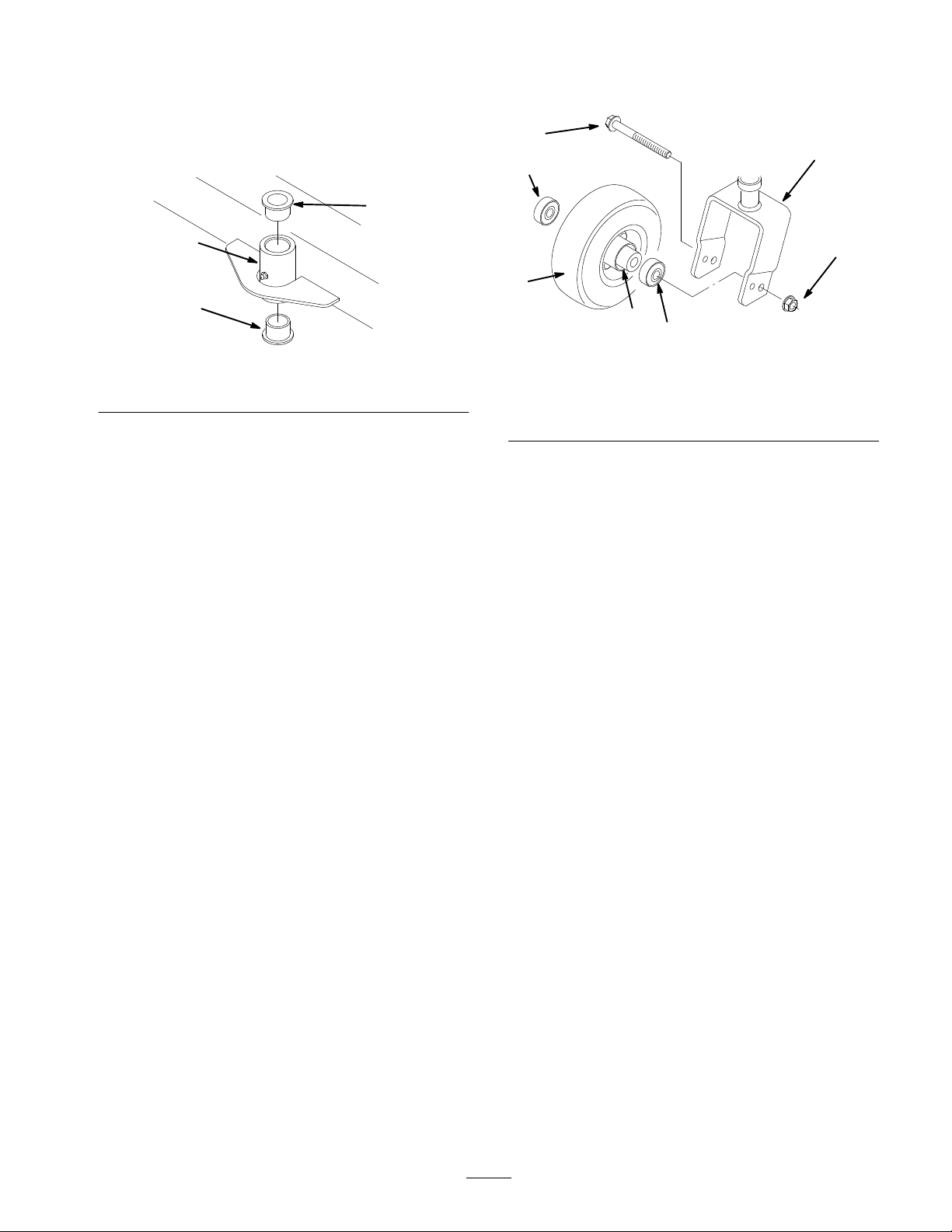
Adjust
castor height for proper broom ground pressure.
The castor wheel height is adjustable from 4 to 7 inches
(10 to 18 cm) in 1/2 inch (1.2 cm) increments by adding
or removing an equal amount of spacers from each castor
wheel.
Start the engine and raise the broom.
1.
2.
Stop the engine.
3.
Remove the cap securing the castor spindle to the
frame bracket (Fig. 12).
4.
Move desired amount of spacers to the top or bottom
of the bracket (Fig. 12). Ensure that the spacers are
equal on both castor wheels and that a thrust washer is
positioned on each side of the frame bracket.
5.
Install the cap and lower the broom (Fig. 12).
4
3
2
1
1. Castor
2. Spacers
3.
Thrust washer
Figure
spindle
12
4.
Frame bracket
5. Cap
Operation
Note:
Always use the traction unit to lift and move the
attachment.
3
o operate the broom, pull the auxiliary hydraulics lever
T
to the operator grip and hold it there.
Tips
• If
•
•
for Sweeping
ground speed is too fast, debris will pile up in front
of the broom, causing it to bulldoze instead of sweep.
This can damage the broom.
More pressure will not give a better sweep, but it will
wear out the broom faster
A level broom lasts longer
.
.
9
Page 10

•
When sweeping, try to keep the flange on the top of
the pivot pin level with the gage plate
(Fig. 13). This will allow you adequate room for
movement if you run over bumps or low areas.
1
1. Pivot
Figure
pin
13
2.
Maintenance
Service
Service
Main pivot shaft–lubricate
Grease fittings
Interval Chart
Operation
2
m–4132
Gage plate
Each
Use8Hours
X X
X X
200
Hours
Storage
Service
Notes
Change brushes
Replace castor fork bushings
Replace castor wheel bearings
Chipped surfaces–paint
POTENTIAL
•
If you leave the key in the ignition switch, someone could start the engine.
WHA
•
Accidental starting of the engine could seriously injur
HOW T
•
Remove the key fr
Greasing
T CAN HAPPEN
and Lubrication
HAZARD
O AVOID THE HAZARD
om the ignition switch befor
Service Interval/Specification
Grease
one fitting on the broom pivot shaft (Fig. 14) with
a corrosion resistant, calcium-sulphonate based grease
before each use. Grease 8 other fittings, located on each
As required
X
When the castor wheel is
wobbly.
X
CAUTION
e you or other bystanders.
e you do any maintenance.
castor shaft (Fig. 15, only one side shown), on the right of
the the axle (Fig. 16), on the motor/axle linkage (Fig. 17),
on the right and left arms (Fig. 18, only one side shown),
and on the loader arm clamps (Fig. 9, only one side
shown), every 8 operating hours. Grease all fittings
immediately after every washing.
10
Page 11

Grease T
ype: corrosion resistant, calcium-sulphonate
based grease (pivot shaft only) and general-purpose grease
(all other fittings).
1
Fitting Locations
Figure
14
m–4132
1. Knuckle
Figure 17
joint inside the broom axle
Figure
18
m–4180
m–4133
m–4130
Figure 15
Figure 16
m–4134
Figure 19
How to Grease
1. Lower
2.
3.
4.
5. W
the broom/loader arms and stop the engine.
Remove the key
.
Clean the grease fittings with a rag.
Connect a grease gun to the fittings.
Pump grease into the fittings until grease begins to
ooze out of the bearings.
ipe up any excess grease.
11
Page 12

Changing
The
axle of the broom holds 27 removable brushes. In
Summer
, install all polypropylene brushes. In the W
Brushes
alternate polypropylene and steel brushes to aid in
removing hard packed snow and ice.
1.
Remove the two bolts securing the side guard plate
and remove the plate (Fig. 20).
2.
Remove the two bolts securing the hydraulic motor
housing (Fig. 20)
3
inter,
7.
Slide a new brush onto the axle assembly so the
alignment pins of the brush ride over
the bottom
of the axle assembly (Fig. 22).
8.
Rotate the next brush 180_ from side to side and top to
bottom and slide it onto the axle assembly so the
alignment pins of the brush ride over
top
bar of axle
assembly (Fig. 22).
1
5
bar
1
2
3
1. Side
guard plate
2. Hydraulic
housing
3. Carefully
Figure
motor and motor
remove the hydraulic motor and motor
20
3. Remove
housing with the axle attached.
4.
Loosen the two bolts securing the axle locking collar
(Fig. 21).
1
m–4136
2
m–4138
Figure
1. Axle
2. Axle
plate
3.
Bolt (3)
9. Repeat
10.
.
11.
12.
steps 7 and 8 until all brushes are installed.
Replace the axle plate and secure it with the bolts and
washers removed in step 5.
Secure the axle locking collar
Slide the hydraulic motor and motor housing into
22
4. W
asher (3)
5. Brushes
.
4 3
position and secure it with the bolts removed in step 2.
13.
Install the side guard and secure it with the bolts
removed in step 1.
m–4137
1. Axle
locking collar
5. Remove
Figure
the three bolts and washers securing the axle
21
2. Loosen
plate on the axle and remove the plate
(Fig. 22)
6.
Slide the brushes of
f of the axle assembly
(Fig. 22).
Replacing
the Castor Fork
Bushings
After
2
12
many hours of operation, the bushings pressed into
the top and bottom of the frame bracket will wear
. To
check the bushings, move the castor fork fore and aft and
from side to side. If the castor spindle is loose in the
bushings, the bushings are worn and must be replaced.
1.
Start the engine and raise the broom to highest
possible position.
2.
Install the cylinder locks then stop the engine.
3.
Remove the cap and thrust washers from top of castor
spindle.
Page 13
4.
Pull the castor spindle out of the bracket, allowing the
thrust washers to remain on the bottom of the spindle.
6.
Remove the other outer bearing (Fig. 24).
5.
Using a pin punch, drive the bushings out of the
bracket (Fig. 23).
2
1
2
Figure
1. Frame
6. Clean
7.
bracket
inside of the bracket to remove any dirt.
Apply grease to the inside and outside of the new
23
2. Bushing
bushings.
Using a hammer and a flat plate, drive the bushings
8.
into the bracket (Fig. 23)
9.
Inspect the castor shaft for wear and replace it if
necessary.
Install the castor spindle into the bracket, place the
10.
thrust washers onto the spindle, and secure it with the
cap.
3
5
2
6
5
Figure
1. Castor
2.
3. Capscrew
7. Check
8.
9.
10.
fork
Castor wheel
the bearings, spacer
for wear
. Replace any defective parts.
Push an outer bearing into the wheel hub.
Slide the bearing spacer into the wheel hub.
Push other bearing into the open side of the wheel hub
24
4. Locknut
5.
Outer bearing
6.
Bearing spacer
, and inside of wheel hub
to captivate the spacer inside.
11.
Install castor wheel assembly in the castor fork and
secure it in place with a capscrew and locknut.
1
4
Servicing
When
a castor wheel becomes wobbly, it usually indicates
a Castor Wheel
that the wheel bearings are worn. Perform this procedure
to fix a wobbly castor wheel.
1.
Start the engine and raise the broom to highest
possible position.
2.
Install the cylinder locks then stop the engine.
3.
Remove locknut and capscrew that secure the castor
wheel assembly in the castor fork
(Fig. 24).
4.
Remove the castor wheel from the fork (Fig. 24).
5.
Remove the outer bearing from wheel hub and allow
the bearing spacer to fall out (Fig. 24).
Storage
1.
Before long term storage wash the attachment with
mild deter
2.
Check the condition of the brushes and replace if
necessary.
Apply grease to all grease fittings.
3.
4.
Check and tighten all bolts, nuts, and screws. Repair or
replace any part that are damaged or worn.
5.
Paint all scratched or bare metal surfaces. Paint is
available from your Authorized Service Dealer
Store the broom in a clean, dry garage or storage area.
6.
Cover it to protect it and keep it clean.
gent and water to remove dirt and grimee.
.
13
Page 14

Troubleshooting
PROBLEM POSSIBLE
Broom does not rotate.
CAUSES
1.
Hydraulic coupler not
completely connected
2.
Defective hydraulic coupler
3.
An obstruction in a hydraulic
hose
4.
Auxiliary valve on the traction
unit is not opening.
CORRECTIVE ACTION
1.
Check and tighten all couplers.
2.
Check couplers and replace
any that are defective.
3.
Find and remove the
obstruction.
4.
Repair the valve.
14
Page 15

Page 16

 Loading...