

Page 1
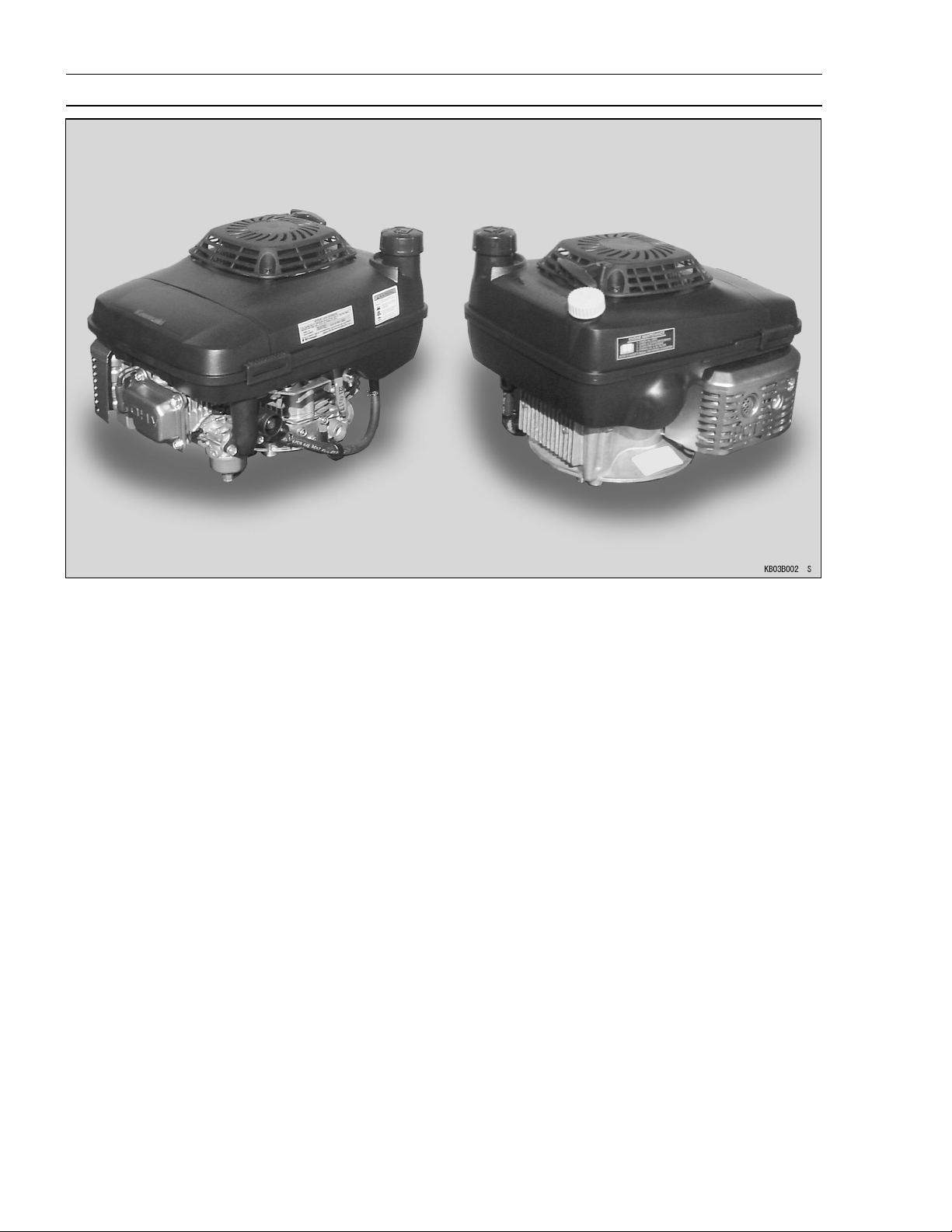
4-stroke air-cooled gasoline engine
Page 2

Page 3

Quick Reference Guide
j
j
j
j
j
j
j
j
j
General Information 1
Periodic Maintenance 2
Fuel System 3
Cooling System 4
Engine Top End 5
Lubrication System 6
Camshaft/Crankshaft 7
Electrical System 8
This quick reference guide will assist
you in locating a desired topic or procedure.
Bend the pages back to match the
•
black tab of the desired chapter number with the black tab on the edge at
each table of contents page.
Refer to the sectional table of con-
•
tents for the exact pages to locate
the specific topic required.
Troubleshooting 9
Page 4

Page 5
FJ180V
4-stroke air-cooled gasoline engine
All rights reserved. No parts of this publication may be reproduced, stored in a retrieval system, or
transmitted in any form or by any means, electronic mechanical photocopying, recording or otherwise,
without the prior written permission of Quality Assurance Department/Consumer Products & Machinery
Company/Kawasaki Heavy Industries, Ltd., Japan.
No liability can be accepted for any inaccuracies or omissions in this publication, although every possible
care has been taken to make i t as complete and accurate as possible.
The right is reserved to make changes at any time without prior notice and without incurring an obligation
to make such changes to products manufactured previously.
All information contained in this publication is based on the latest product information available at the time
of publication. Illustrations and photographs in this publication are intended for reference use only and may
not depict actual model component parts.
© 2002 Kawasaki Heavy Industries, Ltd. First Edition (1) : Nov. 20, 2002 (K)
Page 6
LIST OF ABBREVIATIONS
A ampere(s) lb pound(s)
ABDC after bottom dead center m meter(s)
AC alternating current min minute(s)
ATDC after top dead center N newton(s)
BBDC before bottom dead center Pa pascal(s)
BDC bottom dead center PS horsepower
BTDC before top dead center psi pound(s) per square inch
C
DC direct current rpm revolution(s) per minute
F farad(s) TDC top dead center
F
ft foot, feet V volt(s)
g gram(s) W watt(s)
h hour(s) ohm(s)
L liter(s)
degree(s) Celsius r revolution
degree(s) Fahrenheit TIR total indicator reading
Read OWNER’S MANUAL before operating.
Page 7

EMISSION CONTROL INFORMATION
To protect the environment in which we all live, Kawasaki has incorporated crankcase emission
(1) and exhaust emission (2) control systems (EM) in compliance with applicable regulations of
the United States Environmental Protection Agency and California Air Resources Board.
1. Crankcase Emission Control System
A sealed-type crankcase emission control system is used to eliminate blow-by gases. The
blow-by gases are led to the breather chamber through the crankcase. Then, it is led to the
air cleaner.
Oil is separated from the gases while passing through the inside of the breather chamber
from the crankcase, and then returned back to the bottom of crankcase.
2. Exhaust Emission Control System
The exhaust emission control system applied to this engine consists of a carburetor and
an ignition system having optimum ignition timing characteristics.
The carburetor has been calibrated to provide lean air/fuel mixture characteristics and op-
timum fuel economy with a suitable air cleaner and exhaust system.
TAMPERING WITH EMISSION CONTROL SYSTEM PROHIBITED
Federal law and California State law prohibits the following acts or the causing thereof: (1) the
removal or rendering inoperative by any person other than for purposes of maintenance, repair,
or replacement, of any device or element of design incorporated into any new engine for the
purpose of emission control prior to its sale or delivery to the ultimate purchaser or while it is in
use, or (2) the use of the engine after such device or element of design has been removed or
rendered inoperative by any person.
Among those acts presumed to constitute tampering are the acts listed below:
Do not tamper with the original emission related part:
Carburetor and internal parts
•
Spark plug
•
Magneto or electronic ignition system
•
Fuel filter element
•
Air cleaner elements
•
Crankcase
•
Cylinder head
•
Breather chamber and internal parts
•
Intake pipe and tube
•
Page 8
Foreword
This manual is designed primarily for use by
trained m echanics in a properly equipped shop.
However, it contains enough detail and basic information to make it useful to the owner who desires to perform his own basic maintenance and
repair work. A basic knowledge of mechanics,
the proper use of tools, and workshop procedures must be understood in order to carry out
maintenance and repair satisfactorily. Whenever the owner has insufficient experience or
doubts as to his ability to do the work, all adjustments, maintenance, and repair should be
carried out only by qualified mechanics.
In order to perform the work efficiently and
to avoid costly mistakes, read the text, thoroughly familiarize yourself with the procedures
before starting work, and then do the work carefully in a clean area. Whenever special tools or
equipment are specified, do not use makeshift
tools or equipment. Precision measurements
can only be made if the proper instruments are
used, and the use of substitute tools may adversely affect safe operation.
To get the longest life out of your engine:
Follow the Periodic Maintenance Chart in the
•
Service Manual.
Be alert for problems and non-scheduled
•
maintenance.
Use proper tools and genuine Kaw asaki en-
•
gine parts. Genuine parts provided as spare
parts are listed in the Parts Catalog.
Follow the procedures in this manual care-
•
fully. Don’t take shortcuts.
Remember to keep complete records of main-
•
tenance and repair with dates and any new
parts installed.
How to Use This Manual
In this manual, the product is divided into
its major systems and these systems make up
the manual’s chapters. The Quick Reference
Guide shows you all of the product’s system
and assists in locating their chapters. Each
chapter in turn has its own comprehensive Table of Contents.
For example, if you want ignition coil information, use the Quick Reference Guide to locate
the Electrical System chapter. Then, use the
Table of Contents on the first page of the chapter to find the Ignition coil section.
Whenever you see these WARNING and
CAUTION symbols, heed their instructions!
Always follow safe operating and maintenance
practices.
WARNING
This warning symbol identifies special
instructions or procedures which, if not
correctly followed, could result in per-
sonal injury, or loss of life.
CAUTION
This caution symbol identifies special
instructions or procedures which, if not
strictly observed, could result in dam-
age to or destruction of equipment.
This manual contains four more symbols (in
addition to WARNING and CAUTION) which will
help you distinguish different types of information.
NOTE
This note symbol indicates points of par-
ticular interest for more efficient and con-
venient operation.
Indicates a procedural step or work to be
•
done.
Indicates a procedural sub-step or how to do
the work of the procedural step it follows. It
also precedes the text of a WARNING, CAU-
TION, or NOTE.
Indicates a conditional step or what action to
take based on the results of the test or inspec-
tion in the procedural step or sub-step it fol-
lows.
In most chapters an exploded view illustration
of the system components follows the Table of
Contents. In these illustrations you will find the
instructions indicating which parts require specified tightening torque, oil, grease or a locking
agent during assembly.
Page 9

GENERAL INFORMATION 1-1
General Information
TABLE OF CONTENTS
Before Servicing ........................................................................................................................ 1- 2
Model Identification.................................................................................................................... 1- 4
General Specifications............................................................................................................... 1- 5
Torque and Locking Agent......................................................................................................... 1-6
1
Page 10

1-2 GENERAL INFORMATION
Before Servicing
Before starting to service the engine, carefully read the applicable section to eliminate unnecessary
work. Photographs, diagrams, notes, cautions, warnings, and detailed descriptions have been included wherever necessary. Nevertheless, even a detailed account has limitations, a certain amount
of basic knowledge is required for successful work.
Especially note the following:
(1) Dirt
Before removal and disassembly, clean the engine. Any dirt entering the engine, carburetor, or
other parts, will work as an abrasive and shorten the life of engine. For the same reason, before
installing a new part, clean off any dust or metal filings.
(2) Tightening Sequence
Generally, when installing a part with several bolts, nuts, or screws, start them all in their holes
and tighten them to a snug fit. Then tighten them evenly, in a staggered sequence. This is to
avoid distortion of the part and/or causing gas or oil leakage. Conversely when loosening the
bolts, nuts, or screws, first loosen all of them by about a quarter of a turn and then remove them.
Where there is a tightening sequence indication in this Service Manual, t he bolts, nuts, or screws
must be tightened in the order and method indicated.
(3) Torque
When torque values are given in this Service Manual, use them. Either too little or too much
torque may lead to serious damage. Use a good quality, reliable torque wrench.
(4) Force
Common sense should dictate how much force is necessary in assembly and disassembly. If
a part seems especially difficult to remove or install, stop and examine what may be causing the
problem. Whenever tapping is necessary, t ap lightly using a wooden or plastic-faced mallet. Use
an impact driver for screws (particularly for the removal of screws held by a locking agent) in order
to avoid damaging the heads.
(5) Edges
Watch for sharp edges, especially during m ajor engine disassembly and assembly. Protect your
hands with gloves or a piece of thick cloth when lifting the engine or turning it over.
(6) High-Flash Point Solvent
A high-flash point solvent is recommended to reduce fire danger. A commercial solvent commonly available in North America is Standard solvent (generic name). Always follow manufacturer
and container directions regarding the use of any solvent.
(7) Gasket, O-Ring
Do not reuse a gasket or O-ring once it has been in service. The mating surfaces around the
gasket should be free of foreign matter and perfectly smooth to avoid oil or compression leaks.
(8) Press
A part installed using a press or driver, such as a journal, should first be coated with oil on its
outer or inner circumference so that it will go into place smoothly.
(9) Oil Seal and Grease Seal
Replace any oil or grease seals that were removed with new ones, as removal generally damages seals.
When pressing in a seal which has manufacturer’s marks, press it in with the marks facing out.
Seals should be pressed into place using a suitable driver, which contacts evenly with the side of
seal, until the face of the seal is even with the end of the hole.
(10)Seal Guide
A seal guide is required for certain oil or grease seals during installation to avoid damage to
the seal lips. Before a shaft passes through a seal, apply a little oil, preferably high temperature
grease on the lips to reduce rubber to metal friction.
(11)Lubrication
Engine wear is generally at its maximum while the engine is warming up and before all the
rubbing surfaces have an adequate lubricative film. During assembly, oil or grease (whichever
is more suitable) should be applied to any rubbing surface which has lost its lubricative film. Old
Page 11
GENERAL INFORMATION 1-3
Before Servicing
grease and dirty oil should be cleaned off. Deteriorated grease has lost its lubricative quality and
may contain abrasive foreign particles.
Don’t use just any oil or grease. Some oils and greases in particular should be used only in
certain applications and may be harmful if used in an application for which they are not intended.
This manual m akes reference to molybdenum disulfide grease (MoS2) in the assembly of certain
engine parts. Always check manufacturer recommendations before using such special lubricants.
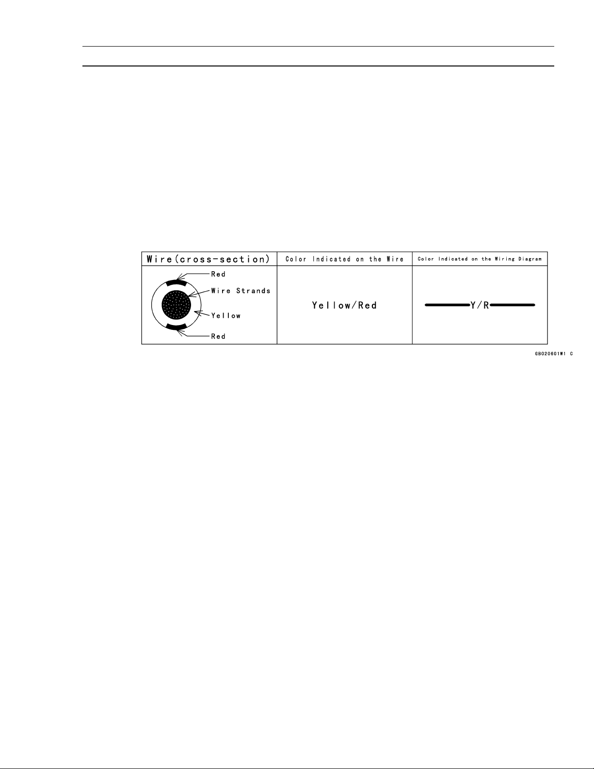
(12)Electrical Wires
All the electrical wires are either single-color or two-color and, with only a few exceptions, must
be connected to wires of the same color. On any of the two-color wires there is a greater amount
of one color and a lesser amount of a second color, so a two-color wire is identified by first the
primary color and then the secondary color. For example, a yellow wire with thin red stripes is
referred to as a " yellow/red" wire; it would be a "red/yellow" wire if the colors were reversed to
make red the main color.
(13)Replacement Parts
When there is a replacement instruction, replace these parts with new ones every time they are
removed. There replacement parts will be damaged or lose their original function once removed.
(14)Inspection
When parts have been disassembled, visually inspect these parts for the following conditions
or other damage. If there is any doubt as to the condition of them, replace them with new ones.
Abrasion Crack Hardening Warp
Bent Dent Scratch Wear
Color change Deterioration Seizure
(15)Specifications
Specification terms are defined as follows:
"Standards" show dimensions or performances which brand-new parts or systems have.
"Service Limits" indicate the usable limits. If the measurement shows excessive wear or deteriorated performance, replace the damaged parts.
Page 12
1-4 GENERAL INFORMATION
Model Identification
Page 13

GENERAL INFORMATION 1-5
General Specifications
Items FJ180V
Type of engine Forced air-cooled, vertical shaft, OHV, 4-stroke gasoline engine
Bore x Stroke 65 mm x 54 mm (2.56 in x 2.13 in)
Piston displacement 179 mL (10.9 cu. in)
Direction of rotation Counterclockwise facing the PTO shaft
Compression release Automatic compression release
High idle speed 3200 rpm
Ignition system Flywheel magneto with CDI
RFI Per Canada and U.S.A. requirements
Starting system Recoil starter
Spark plug NGK BPR5ES
Carburetor Float type, fixed main jet
Air cleaner Dual stage element, dry type
Governor Flyweight all speed governor
Lubrication system Pressure feed by positive displacement pump
Oil capacity
(when engine is
completely dry)
Cooling system Forced air cooling by fan
Dimensions (L x W x H ) 390 mm x 307 mm x 284mm (15.4 in x 12.1 in x 11.2 in)
Dry weight 15.0 kg (33.3 lb)
Specifications subject to change without notice.
0.65 L (0.69 US-qt)
Page 14
1-6 GENERAL INFORMATION
Torque and Locking Agent
The following tables list the tightening torque for the major f asteners, and the parts requiring use of
a non-permanent locking agent or liquid gasket.
Letters used in the "Remarks" column mean:
L : Apply a non-permanent locking agent to the threads.
M : Apply a molybdenum disulfide lubricant (grease or oil) to the threads, seated surface, or washer.
O : Apply an oil to the threads, seated surface, or washer.
S : Tighten the fasteners following the specified sequence.
SS : Apply silicone sealant.
Fastener
N·m
Fuel System:
Throttle Valve Screw 0.7 0.07 6in·lb
Main Jet 1.1 0.11 9.7 in·lb
Governor Arm Clamp Nut 7.8 0.80 69 in·lb
Priming Nut 1.2 0.12 11 in·lb
Fuel Tank Cover Bolts 6.9 0.70 61 in·lb
Tank Drain Bolt 6.9 0.70 61 in·lb
Float Chamber Mounting Bolt 5.4 0.55 48 in·lb
Drain Screw 4.2 0.43 37 in·lb
Cooling System:
Flywheel Bolt 42 4.3 31
Engine Top End:
Cylinder Head Bolts 22 2.2 16 =S
Valve Clearance Lock Screws 6.9 0.70 61 in·lb
Connecting Rod Big End 5.9 0.60 52 in·lb =O
Cap Bolts
Rocker Arm Bolts 28 2.8 20
Rocker Cover Mounting Bolts 5.9 0.60 52 in·lb
Spark Plug 22 2.2 16
Muffler Cover Self Tap Bolt (1) 6.9 0.70 61 in·lb
Lubrication System:
Oil Drain Plug 22 2.2 16 in·lb
Oil Filter Cover Bolt 6.9 0.70 61 in·lb
Camshaft/Crankshaft:
Crankcase Cover Bolts 8.8 0.90 78 in·lb =S
Electrical System:
Flywheel Bolt 42 4.3 31
Recoil Starter Mounting Bolts 6.9 0.70 61 in·lb
Recoil Starter Set Screw 1.0 0.10 8.9 in·lb
Spark Plug 22 2.2 16
Brake Lever Assembly Mounting Bolt 6.9 0.70 61 in·lb
Kill Switch Bolt 1.5 0.15 13 in·lb
Brake Arm Mounting Bolt 9.3 0.95 82 in·lb
Torque
Remarks
kgf·m ft·lb
Page 15

GENERAL INFORMATION 1-7
Torque and Locking Agent
The table below, relating tightening torque to thread diameter, lists the basic torque for the bolts and
nuts. Use this table for only the bolts and nuts which do not require a specific torque value. All of the
values are for use with dry solvent-cleaned threads.
Basic Torque for General Fasteners
Threads dia Torque
(mm) N·m kgf·m ft·lb
4 2.0 0.20 17 in·lb
5 3.4 0.35 30 in·lb
6 5.9 0.60 52 in·lb
8 15 1.5 11
Page 16

Page 17

PERIODIC MAINTENANCE 2 -1
Periodic Maintenance
TABLE OF CONTENTS
Periodic Maintenance Chart ...................................................................................................... 2-2
Specifications ............................................................................................................................ 2- 3
Special Tools ............................................................................................................................. 2- 4
Periodic Maintenance Procedures............................................................................................. 2- 5
Fuel System............................................................................................................................ 2- 5
High Idle Speed Adjustment ................................................................................................ 2- 5
Fuel System Cleanliness Inspection .................................................................................... 2- 5
Fuel Filter Inspection............................................................................................................2-6
Air Element Removal ........................................................................................................... 2- 6
Air Element Installation ........................................................................................................ 2-7
Air Element Cleaning and Inspection................................................................................... 2- 7
Air Cleaner Housing (Case and Body) Inspection ............................................................... 2- 8
Engine Top End ...................................................................................................................... 2- 8
Cylinder Head Cleaning and Inspection............................................................................... 2- 8
Valve Clearance Inspection ................................................................................................. 2- 8
Valve Clearance Adjustment ................................................................................................ 2- 9
Valve Seat Inspection .......................................................................................................... 2- 9
Valve Seat Repair ................................................................................................................ 2-10
Lubrication System ................................................................................................................. 2-13
Oil Level Inspection..............................................................................................................2-13
Oil Change ........................................................................................................................... 2-13
Electrical System .................................................................................................................... 2-14
Spark Plug Cleaning and Inspection.................................................................................... 2-14
Spark Plug Gap Inspection .................................................................................................. 2-14
2
Page 18
2-2 PERIODIC MAINTENANCE
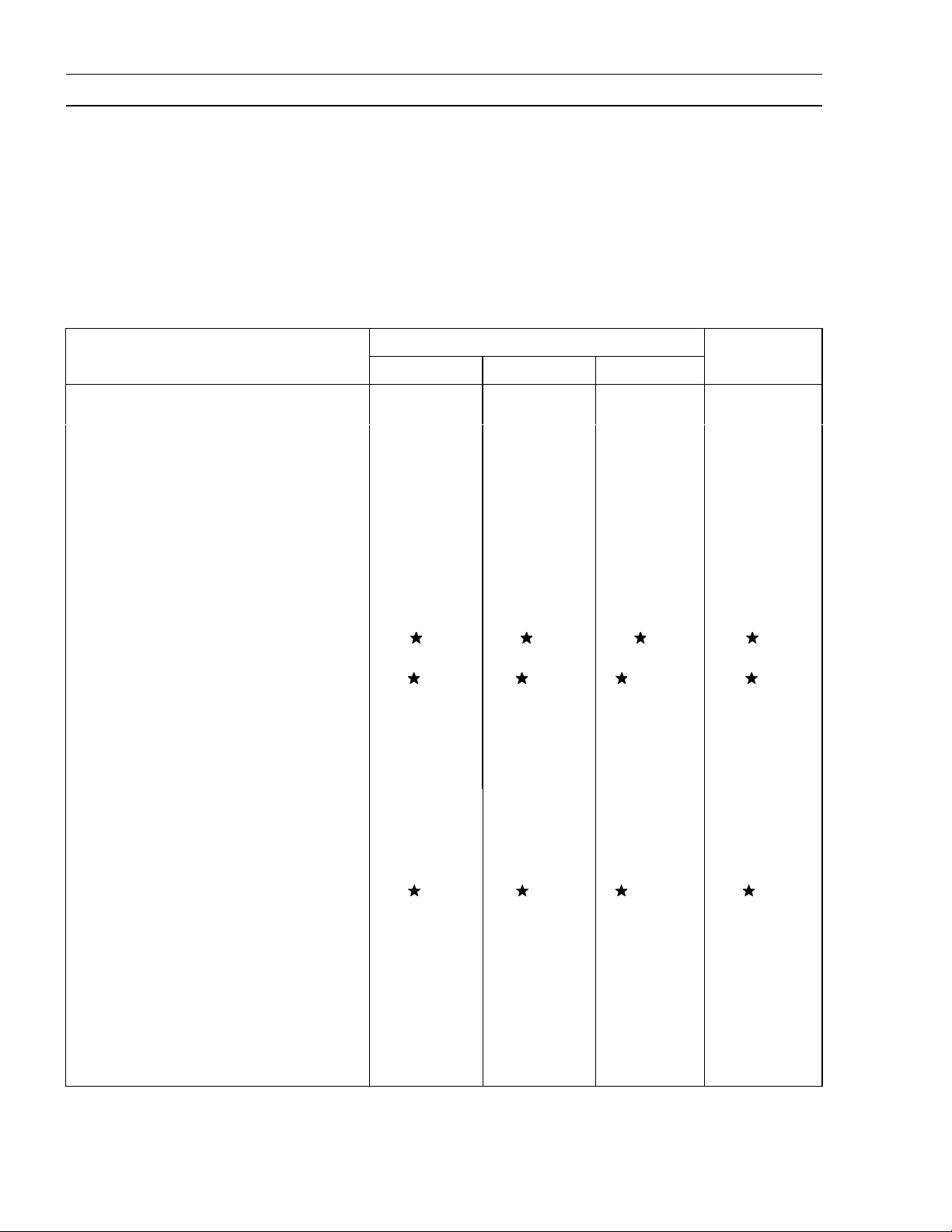
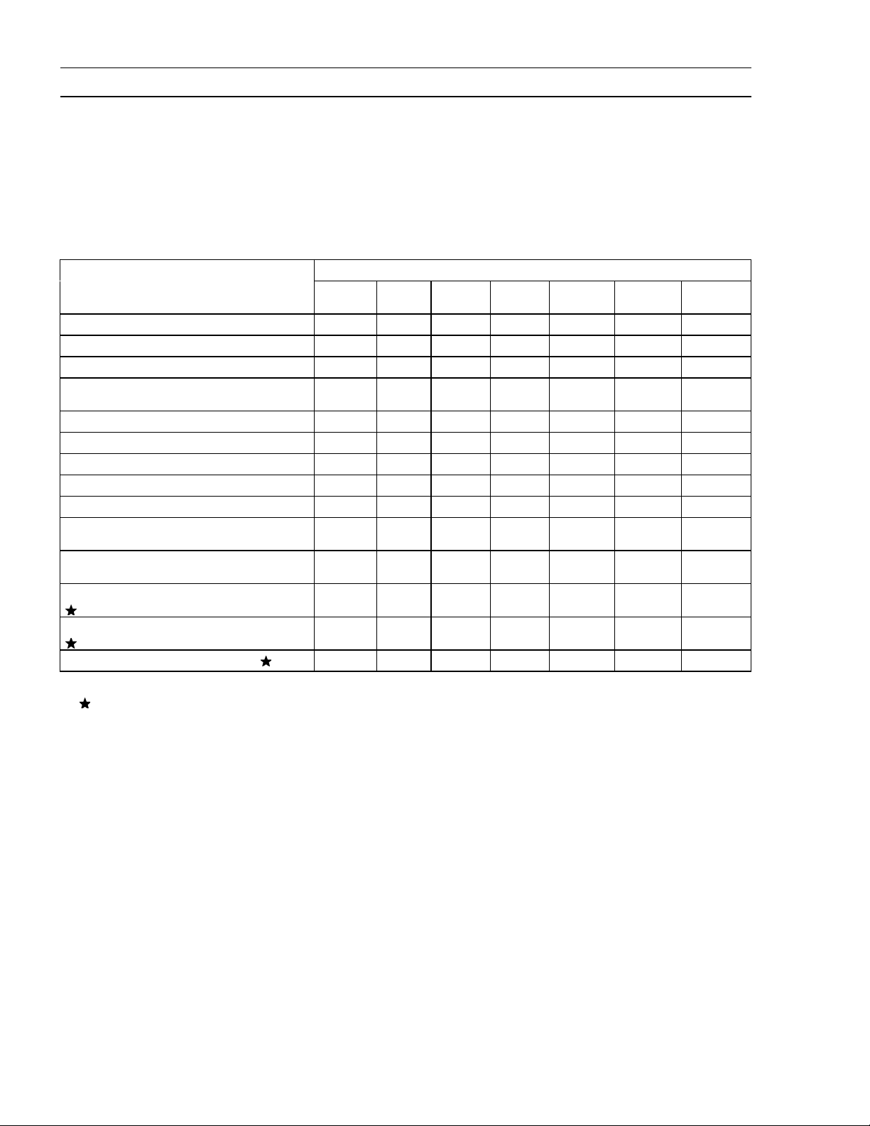
Periodic Maintenance Chart
To ensure satisfactory operation over an extended period of time, any engine requires normal maintenance regular intervals. The Periodic Maintenance Chart below shows periodic inspection and
maintenance items and suitable intervals. The bullet mark (
should be performed at that interval.
Some adjustments require the use of special tools or other equipment. An electronic tachometer
will facilitate setting idle and running speeds.
) designates that the corresponding item
•
•
INTERVAL
Every
50 hr.
100 hr.
•
Every
•
•
Every
200 hr.
•
OPERATION
Daily
Check or clean air intake screen
Check and add engine oil
Check for fuel and oil leakage
Check for loose or lost nuts and
screws
Clean air cleaner foam element (1)
Clean air cleaner paper element (1)
Tighten nuts and screws
Change engine oil
Clean and re-gap spark plug
Change air cleaner paper element
(1)
Clean dust and dirt from cylinder
and cylinder head fins (1)
Check and adjust valve clearance
Clean and lap valve seating surface
Clean combustion chamber
(1): Service more frequently under dusty conditions.
: These items must be performed with the proper tools. See your authorized Kawasaki Engine
Dealer for service, unless you have the proper equipment and mechanical proficiency.
First 8
hr.
•
•
•
•
Every
25 hr.
• •
Every
300 hr.
•
•
•
•
Page 19

PERIODIC MAINTENANCE 2 -3
Specifications
Item Standard
Fuel System
High idle speed 3200 r/min (rpm)
Air cleaner:
Type Dual stage filtration system
Pre-cleaner Foam element
Second-stage cleaner Paper element
Engine Top End
Valve clearance Intake Exhaust 0.10 ~ 0.15 mm (0.004 ~ 0.006 in.)
Valve seating surface angle Intake Exhaust
Valve seating surface width Intake Exhaust 0.6 ~ 0.9 mm (0.024 ~ 0.035 in.)
Lubrication System
Engine oil:
Type SF, SG, SH or SJ class
Viscosity SAE30, SAE10W-30
Capacity [When engine is completely dry]
Level Operating range (grid area) on dipstick
45
0.65 L (0.69 US-qt)
Electrical System
Spark plug gap 0.75 mm (0.030 in.)
Page 20
2-4 PERIODIC MAINTENANCE
Special Tools
Valve Seat Cutter, 45 - f27.5: 57001–1114
Valve Seat Cutter, 32 - f25.0: 57001–1118
Valve Seat Cutter, 32 - f28.0: 57001–1119
Valve Seat Cutter Holder Bar: 57001–1128
Valve Seat Cutter Holder - f6.0: 57001–1360
Page 21
Periodic Maintenance Procedures
Fuel System
High Idle Speed Adjustment
CAUTION
Do not adjust high idle speed with the air cleaner
removed.
Start and warm up the engine throughly.
•
WARNING
Always keep your hands clear of the moving parts.
Move the throttle lever at a dash to the high idle position.
•
Loosen the control panel mounting bolts [A] enough to
•
move the control panel assembly.
Carefully move the control panel assembly right or left to
•
obtain the specified high idle speed.
PERIODIC MAINTENANCE 2 -5
High Idle Speed
3200 rpm
Tighten the Mounting bolts.
•
Fuel System Cleanliness Inspection
WARNING
Gasoline is extremely flammable and can be explosive under certain conditions. Turn the engine
switch stop position. Do not smoke. Make sure the
area is well-ventilated and free from any source of
flame or sparks, this includes any appliance with a
pilot light.
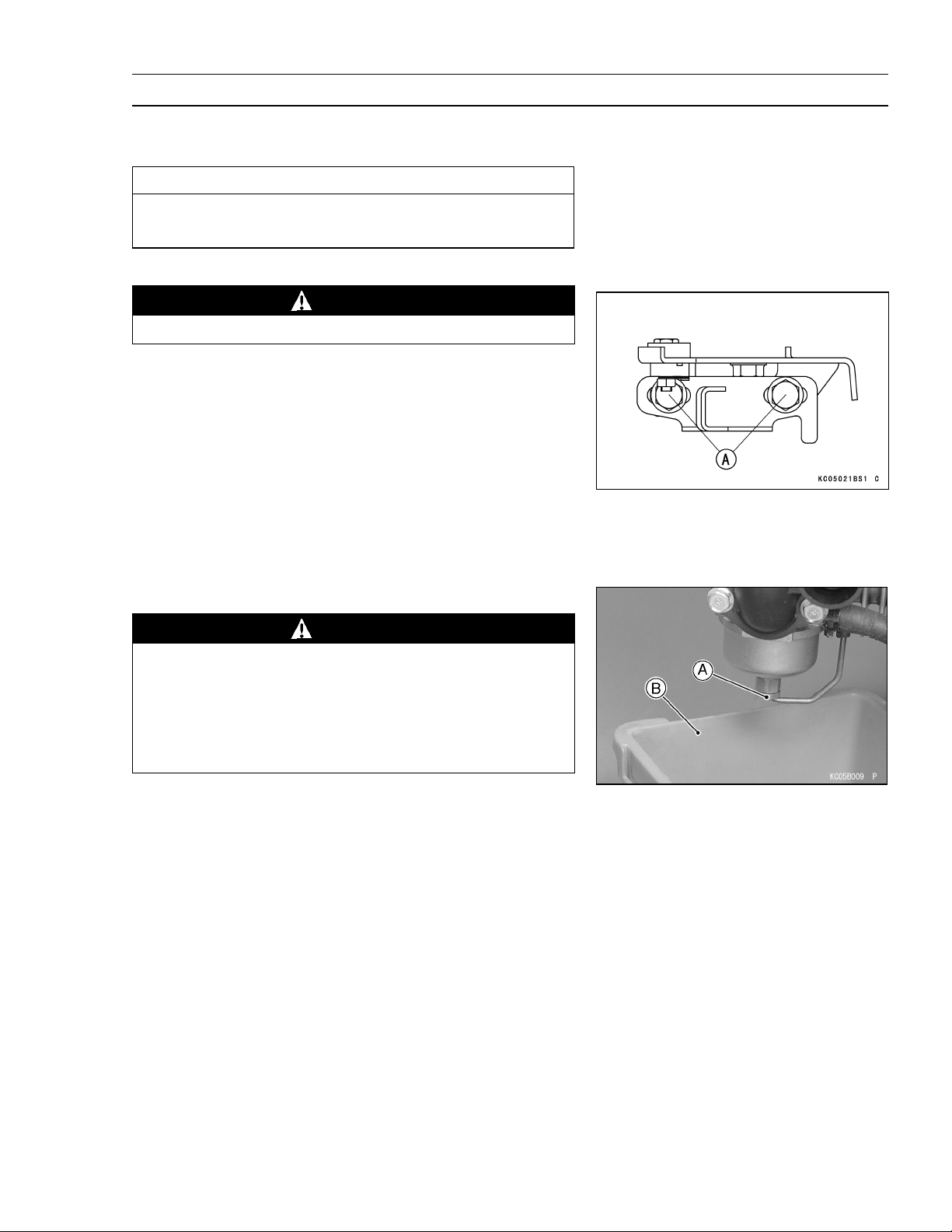
Remove the primer pipe from the tube.
•
Place a suitable container [B] under the drain screw [A]
•
on the carburetor.
Loosen the drain screw to drain the carburetor and check
•
to see if water or dirt has accumulated in the carburetor.
Tighten the drain screw.
•
Torque - Drain Screw: 4.2 N·m (0.43 kgf·m, 37 in·lb)
Install the primer pipe in the tube (see Fuel System chap-
•
ter).
If any water or dirt is found, clean the carburetor and fuel
•
tank (see Fuel System chapter).
Page 22
2-6 PERIODIC MAINTENANCE
Periodic Maintenance Procedures
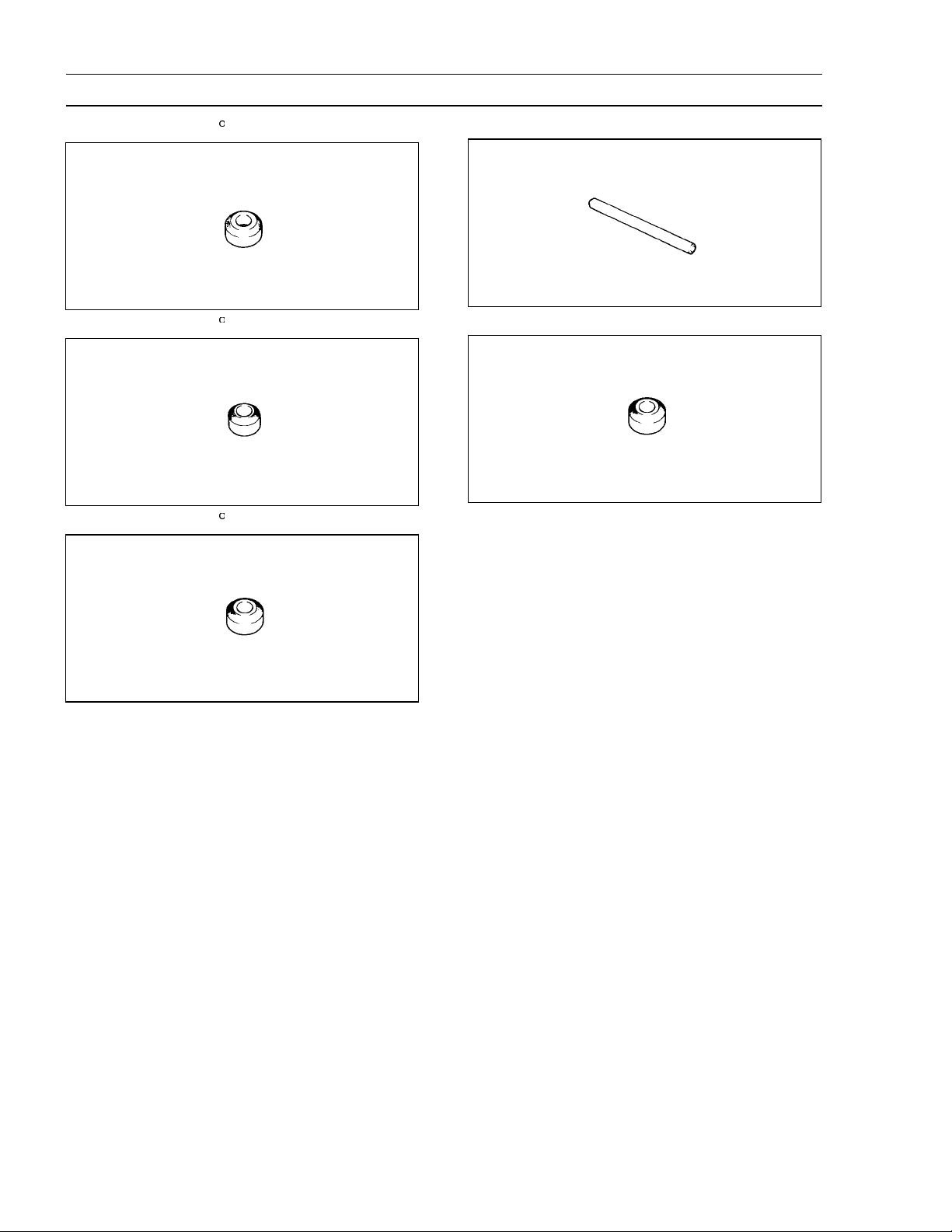
Fuel Filter Inspection
Visually insect the fuel filter [A].
•
If the filter is clear with no signs of dirt or other contami-
nation, it is OK and need not be replaced.
If the filter is dark or looks dirty, replace with a new one.
Also check the rest of the fuel system for contamination.
Check the O-ring at the tank drain for damage. Replace
•
the O-ring with a new one if it is damaged.
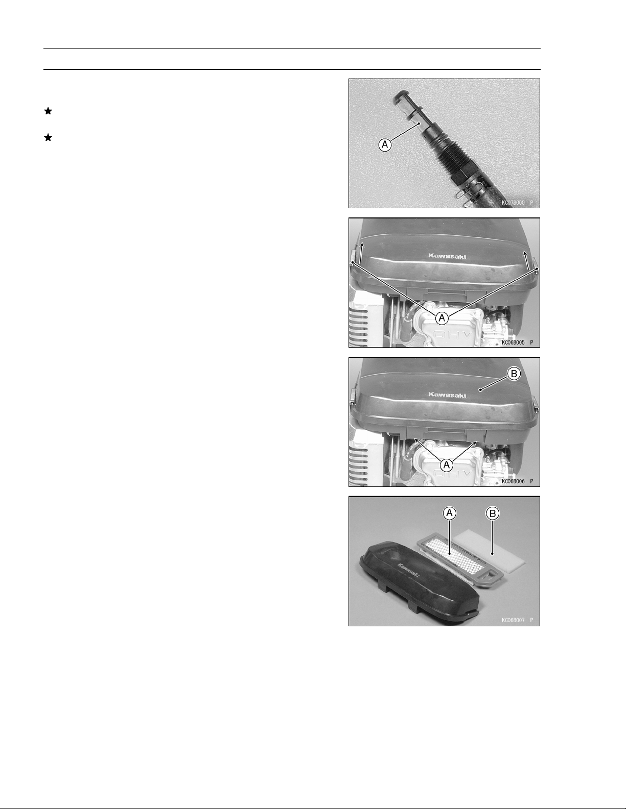
Air Element Removal
Move the holders [A].
•
Push up the latches [A] and remove the air cleaner case
•
[B].
Remove:
•
Paper Element [A]
Foam Element [B]
Page 23
Periodic Maintenance Procedures
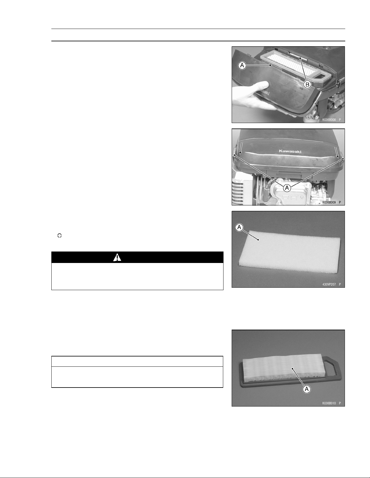
Air Element Installation
Install:
•
Foam Element
Paper Element
Install the hollow [A] of the air cleaner case and projection
•
[B] of the air cleaner body are fitting.
Move the holders [A].
•
PERIODIC MAINTENANCE 2 -7
Air Element Cleaning and Inspection
NOTE
In dusty areas, the elements should be cleaned more
frequently than the recommended intervals.
WARNING
Because of the danger of highly flammable liquids,
do not use gasoline or a low flash-point solvent to
clean the element.
Remove the paper element and the foam element.
•
Clean the foam element [A] in a bath of detergent and wa-
•
ter, and let the element air-dry throughly before installing
it.
Clean the paper element [A] by tapping it gently on a flat
•
surface to remove dust. If the element is very dirty, replace it with a new one.
CAUTION
Do not use compressed air to clean the paper element. Do not oil the paper or foam element.
Page 24
2-8 PERIODIC MAINTENANCE
Periodic Maintenance Procedures
Air Cleaner Housing (Case and Body) Inspection
Clean the housing with detergent and water and dry thor-
•
oughly.
Check the housing for deformation or other damage. The
•
housing must seal well and permit only filtered air to reach
the carburetor.
If the housing is damaged, it must be replaced.
Check that no foreign material is obstructing the air pas-
•
sage.
Engine Top End
Cylinder Head Cleaning and Inspection
Remove the cylinder head (see Engine Top End chapter).
•
Scrape the carbon deposits from the head and exhaust
•
port with a suitable tool [A].
To avoid gouging, use scrapers that are made of a m ate-
•
rial that w ill not cause damage.
Clean the head in a bath of high flash-point solvent and
•
dry it with com pressed air.
WARNING
Clean the cylinder head in a well-ventilated area,
and take care that there are no sparks or flame any-
where near the working area, this includes any ap-
pliance with a pilot light. Do not use gasoline or a
low flash-point solvent to clean the cylinder head.
A fire or explosion could result.
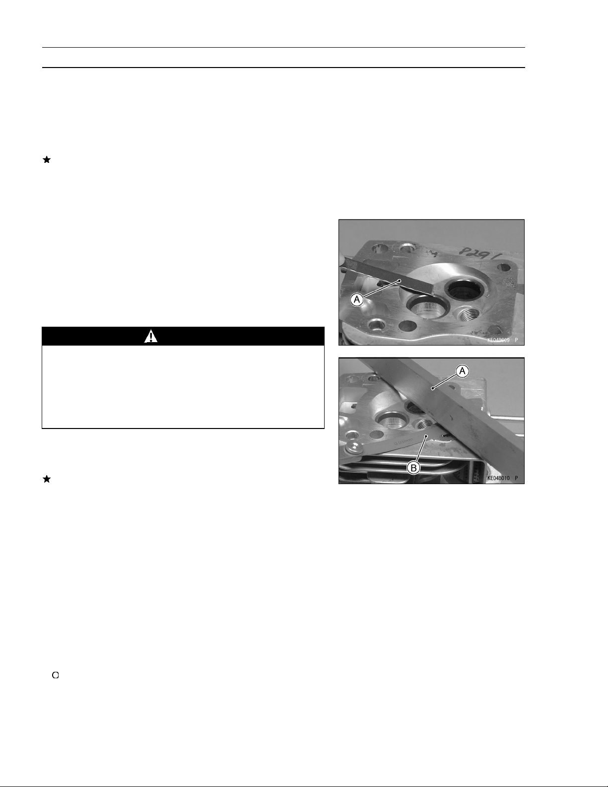
Straight edge [A] across the mating surface of the head at
•
several different points, and measure warp by inserting a
thickness gauge [B] between the straightedge and head.
If warp exceeds the service limit, repair the mating sur-
face. Replace the cylinder head if the mating surface is
badly damaged.
Cylinder Head Warp
Service Limit: 0.03 mm (0.001 in.)
Check the cylinder head for cracks or other damage.
•
Cracks not visible to the eye may be detached by using
•
a metal crack detection system (Visual color check: com-
monly found at automotive parts tore.).
If a crack is present in the cylinder head, replace it.
•
Inspect the mating surface for burrs and nicks.
•
Valve Clearance Inspection
NOTE
Valve clearance must be checked when the engine is
cold (at room temperature).
Remove the rocker cover (see Engine Top End chapter).
•
Place the piston at top dead center (TDC) of the compres-
•
sion stroke turning the crankshaft rotational direction.
Page 25
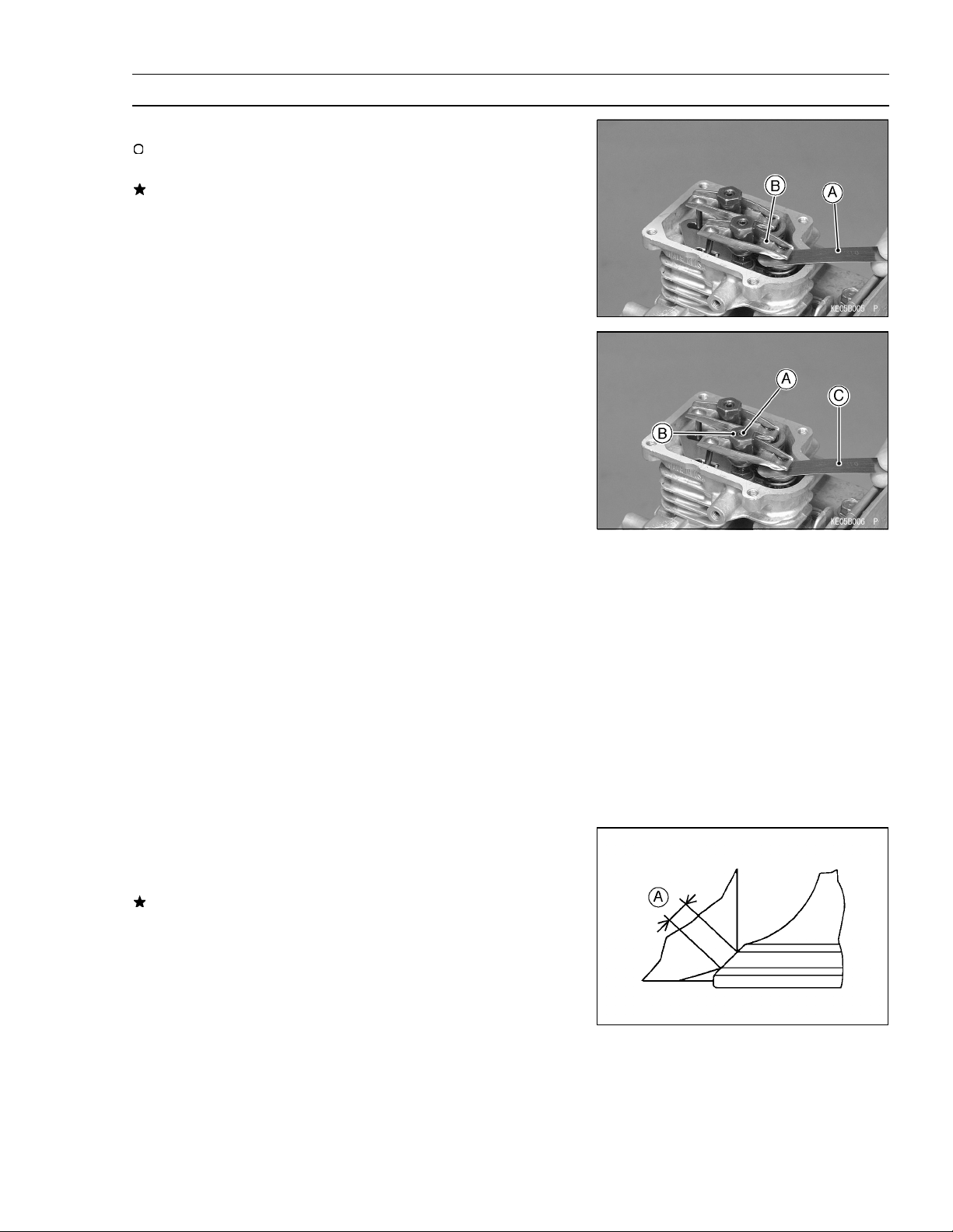
Periodic Maintenance Procedures
Then check the valve clearance.
•
Using a thickness gauge [A], measure the valve clearance
beween the rocker arm [B] and the valve stem end.
If the valve clearance is incorrect, adjust it.
Valve Clearance (when cold)
Intake, Exhaust
Valve Clearance Ad justment
Since valve repairs change the valve clearance, adjust
•
the valve clearance to the specification.
Assemble the cylinder head and install the cylinder head
•
assembly on the block (see Engine Top End chapter).
Turn the crankshaft to the proper direction until the piston
•
is at TDC of the compression stroke (described above).
Loosen the lock screws [A] and valve clearance adjusting
•
nuts [B].
Insert a 0.10 mm (0.004 in.) thickness gauge [C] between
•
the rocker arm and valve stem, and tighten the adjusting
nut until the thickness gauge begins to bind between the
rocker arm and valve stem end. Use a sweeping motion
with the thickness gauge while making this adjustment.
0.10 ~ 0.15 mm (0.004 ~ 0.006in.)
PERIODIC MAINTENANCE 2 -9
Valve Clearance (when cold)
Intake, Exhaust
Holding the adjusting nut with a wrench, tighten the lock
•
screw to the specified torque.
Torque - Valve Clearance Lock Screws: 6.9 N·m (0.70
kgf·m, 61 in·lb)
Do not overtighten.
•
Remeasure any clearance that was adjusted. Readjust if
•
necessary.
Valve Seat Inspection
Remove the valve (see Engine Top End chapter).
•
Inspect the valve seats for damage.
•
If the seats are warped or distorted beyond reconditioning, replace the cylinder head.
Pitted or worn valve seats can be refaced. Lap the valves
•
to the seats after refacing.
Coat the valve seat with machinist’s dye.
•
Push the valve into the guide.
•
Rotate the valve against the seat with a lapping tool.
•
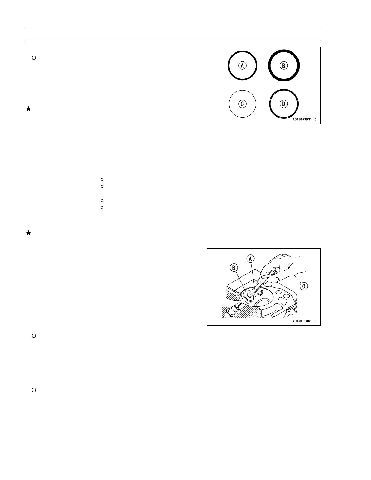
Pull the valve out, and check the seating pattern on the
•
valve head. It must be the correct width [A] and even all
the way around.
0.10 ~ 0.15 mm (0.004 ~ 0.006in.)
Page 26
2-10 PERIODIC MAINTENANCE
Periodic Maintenance Procedures
NOTE
The valve stem and guide must be in good condition or
this check will not be valid.
Good [A]
Toowide[B]
Too narrow [C]
Uneven [D]
If the valve seating pattern is not correct, repair the seat.
Valve Seating Surface Width (STD)
Inlet, Exhaust
Valve Seat Repair
Follow the manufacturer’s instructions for use of valve
•
seat cutters.
Special Tools
Intake Valve:
Seat Cutter
Outside Cutter
Exhaust Valve:
Seat Cutter
Outside Cutter
Valve S eat Cutter Holder-f6.0
Valve Seat Cutter Holder Bar
If the manufacturer’s instructions are not available, use
the following procedure.
0.6 ~ 0.9 mm (0.024 ~ 0.035 in.)
:
45
32
45
32
- f27.5
- f28.0
- f27.5
- f25.0
57001-1114
:
57001-1119
:
57001-1114
:
57001-1118
:
57001-1360
:
57001-1128
Seat Cutter Operating Cares:
1. This valve seat cutter is designed only for valve seat re-
pair. Therefore the cutter must not be used for other purposes.
2. Do not drop or hit the valve seat cutter, or the diamond
particles may fall off.
3. Do not fail to apply engine oil to the valve seat cutter
before grinding the seat surface. Also wash off ground
particles sticking to the cutter with washing oil.
NOTE
Do not use a wire brush to remove the metal particles
from the cutter. It will take off the diamond particles.
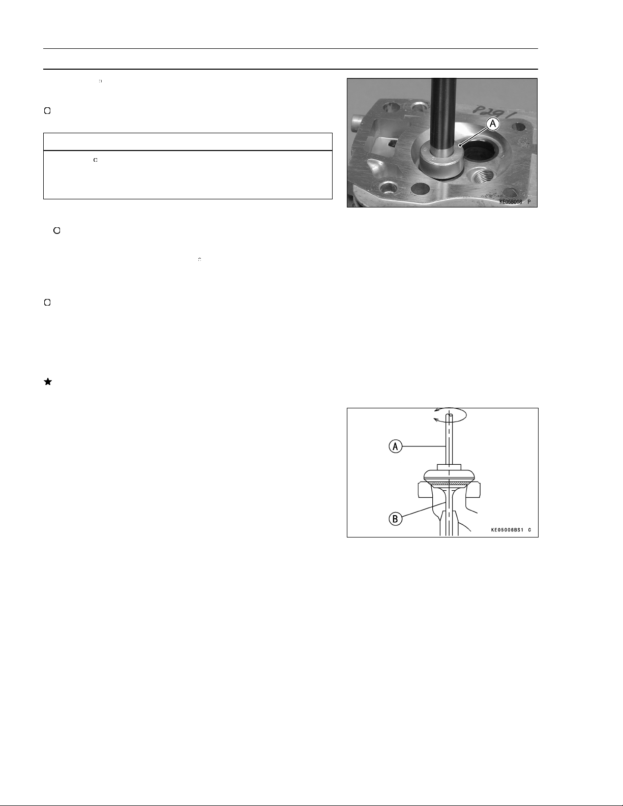
4. Setting t he valve seat cutter holder [A] in position, op-
erate the cutter [B] with one hand [C]. Do not apply too
much force to the diamond portion.
NOTE
Prior to grinding, apply oil to the cutter, and during t he
operation wash off any ground particles sticking to the
cutter with washing oil.
5. After use wash the cutter with washing oil and apply a
thin layer of engine oil before storing.
Page 27
Periodic Maintenance Procedures
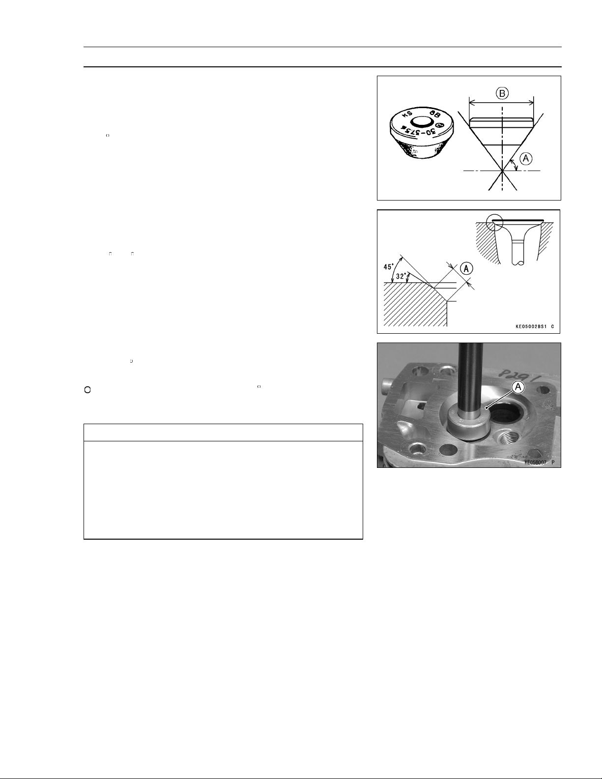
Marks Stamped on the Cutter:
The marks stamped on the back of the cutter represent the
following.
1 Cutter number, selected from 1 to 12
30
37.5 Cutter diameter of cutter [B]
KS8B Manufactured lot number
Operating Procedures:
Clean the seat area carefully.
•
Recondition the valve seats with the valve seat cutters
•
(45
,32) and lap the valves.
Check the seats for good contact all the way around with
•
machinist’s dye.
Measure the seat width [A]. If it is more than the STD
•
width, the seating surface should be refaced.
If the valve seating pattern is not correct, repair the seat.
•
Cutter angle [A]
PERIODIC MAINTENANCE 2-11
Coat the seat with machinist’s dye.
•
Fit a 45 seat cutter [A] to the holder and slide it into the
•
valve guide.
Resurface the valve seat with a 45 cutter, removing only
enough material to produce a smooth and concentric
seat.
CAUTION
Do not grind the seat too much. Overgrinding will
reduce valve clearance by sinking the valve into the
head. If the valve sinks too far into the head, i t will
be impossible to adjust the clearance, and the cylinder head must be replaced. Do not turn the cutter
counterclockwise or drop it against the seat, or it
will be dulled.
Page 28
2-12 PERIODIC MAINTENANCE
Periodic Maintenance Procedures
Use a 32 seat cutter [A] to narrow the seat width to the
•
STD width.
Turn the seat cutter one turn at a time while pressing down
very lightly. Check the seat width after each turn.
CAUTION
The 32 cutter removes material very quickly.
Check the seat width frequently to prevent over
grinding.
NOTE
Keep the seat width as close as possible to the STD
width.
Make a light pass with the 45 cutter to remove any pos-
•
sible burrs at the edge of the seat.
After resurfacing the seat, inspect for even valve seating.
•
Apply a machinist’s dye to the valve face, insert the
valve, and snap it closed against the seat several times.
The valve surface should show good contact all the way
around. Be sure the valve seat is centered on the valve
face. The position of the valve in the seat is evident after
lapping the valve.
If the seat does not make proper contact, lap the valve
into seat with a vacuum cap tool.
Coat the face of valve sparingly with a fine lapping com-
•
pound.
Use the vacuum cup tool [A], to grip top of the valve [B].
•
Rotate the valve in a circular motion to lap the valve to the
seat.
Lift the valve slightly from the seat every 8 to 10 strokes,
•
continue lapping operation until a uniform ring appears
around entire surface of the valve face.
When lapping is completed, wash all parts in solvent to
•
remove lapping compound. Dry the parts thoroughly.
Note the position of the lapping m ark on the valve face.
•
The lapping mark should appear on or near the center of
the valve face.
When the engine is assembled, be sure to adjust the valve
•
clearances (see Valve Clearance Adjustment).
Page 29
Periodic Maintenance Procedures
Lubrication System
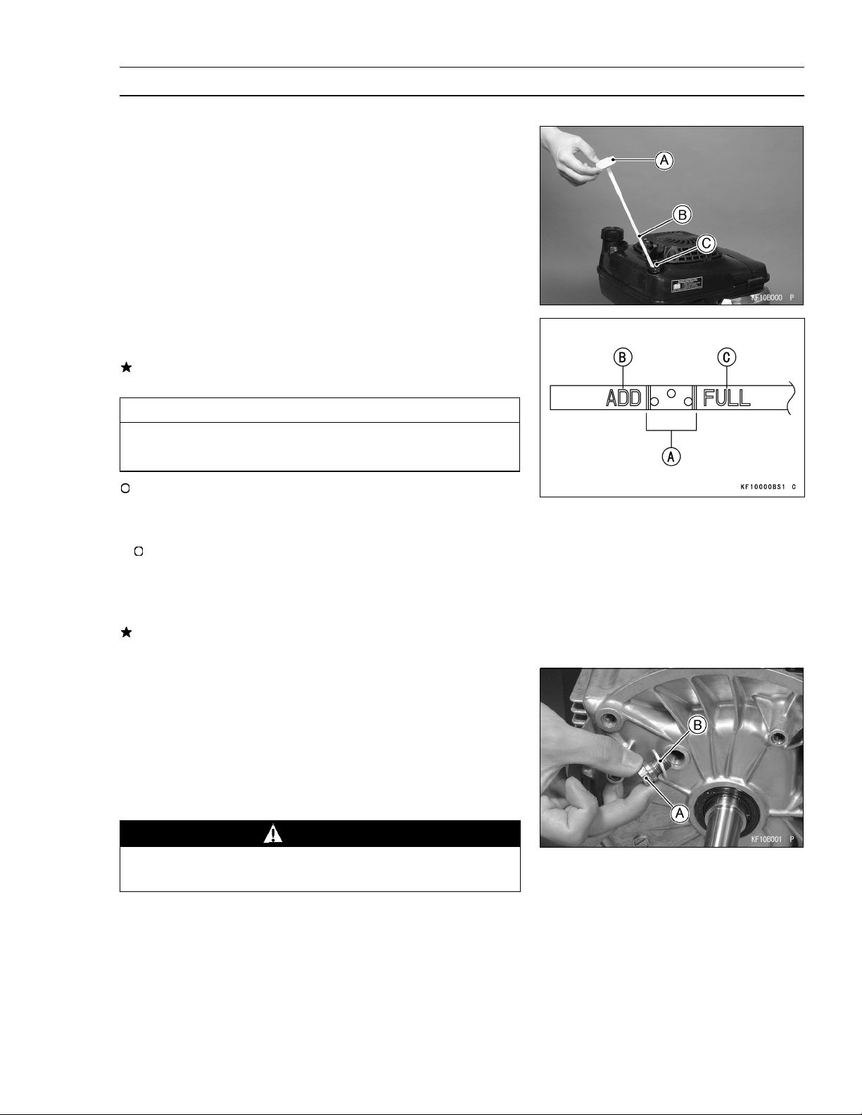
Oil Level Inspection
Place the engine on a level surface.
•
Remove the oil filler cap [A] and wipe its dipstick [B] with
•
a clean cloth.
Insert the dipstick into gauge hole [C] without screwing it
•
in, then check the oil Level.
The oil level should be the operating range [A] (grid area)
•
on the dipstick.
If the oil level is below “ADD” range [B], add enough engine oil to bring oil level to the operating range.
CAUTION
Do not add more oil above the operating range. Excess oil will cause a smoking condition.
PERIODIC MAINTENANCE 2-13
Use the same type and make of oil that is already in the
engine.
NOTE
If the engine oil type and make are unknown, use any
brand of the specified oil to top up the level in preference
to running the engine with the oil level low. Then at your
earliest convenience, change the oil completely.
If the oil level is above “FULL” range [C], drain the excess
oil by loosening the drain plug.
Oil Change
Change the oil after first 8 hours of operation. Thereafter
•
change oil every 100 hours.
Start and warm up the engine so the oil will drain easily.
•
Stop the engine.
Place the engine on a level surface.
•
Place a suitable container under the engine.
•
Remove the drain plug [A] and drain the oil.
•
WARNING
Be careful of hot oil when drained. It m ay be hot
enough to burn you severely.
Check the washer [B] at the drain plug for damage. Re-
•
place the washer with a new one if it is damaged.
Install the drain plug with the washer and tighten it.
•
Torque - Oil Drain Plug : 22 N·m (2.2 kgf·m, 16 ft·lb)
Page 30
2-14 PERIODIC MAINTENANCE
Periodic Maintenance Procedures
Remove the oil filler cap and pour in the specified type
•
and amount of oil.
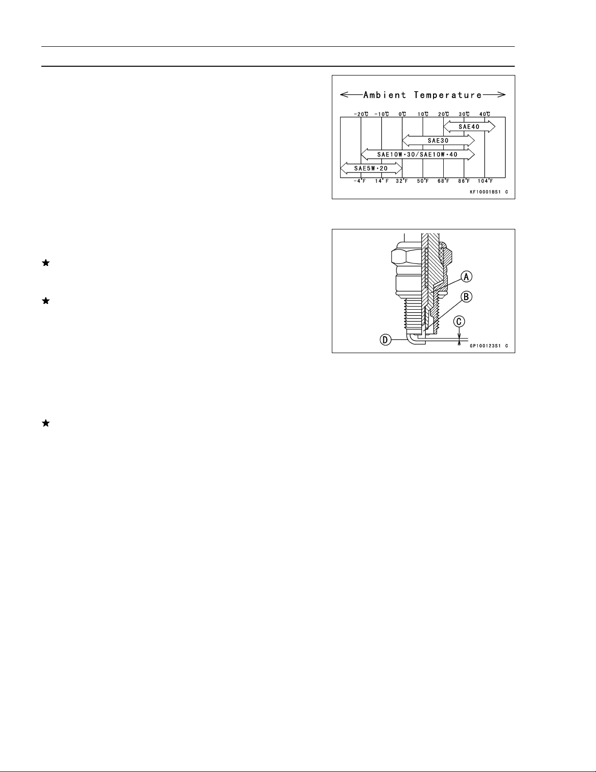
Engine Oil :
Type:
Viscosity:
Capacity:
Electrical System
Spark Plug Cleaning and Inspection
Remove the spark plug (See Electrical System chapter).
•
If the plug is oily or has carbon build up on it, clean the
plug using a high flash-point solvent and a wire brush or
other suitable tool.
If the spark plug electrodes are corroded or damaged,
or if the insulator is cracked, replace the plug. Use the
standard spark plug or its equivalent.
Insulator [A]
Center Electrode [B]
Plug Gap [C]
Side Electrode [D]
SF, SG, SH or SJ Class
SAE30, SAE10W-30
[When engine is completely dry]
0.65 L (0.69 US-qt)
Spark Plug Gap Inspection
Measure the gap with a wire-type thickness gauge.
•
If the gap is incorrect, carefully bend the side electrode
with a suitable tool to obtain the correct gap.
Spark Plug Gap
Standard: 0.75 mm (0.030 in.)
Page 31

FUEL SYSTEM 3-1
Fuel System
TABLE OF CONTENTS
Exploded View........................................................................................................................... 3- 2
Specifications ............................................................................................................................ 3- 6
Governor Link Mechanism......................................................................................................... 3-7
Control Panel Assembly Removal ....................................................................................... 3- 7
Control Panel Assembly Installation .................................................................................... 3- 7
Governor Arm Removal ....................................................................................................... 3- 7
Governor Arm Installation .................................................................................................... 3- 8
Governor Assembly Inspection and Removal...................................................................... 3- 8
Governor Assembly Installation ........................................................................................... 3- 9
Governor Shaft Removal ..................................................................................................... 3- 9
Governor Shaft Installation .................................................................................................. 3- 9
Carburetor ................................................................................................................................. 3-10
Fuel and Air Flow ................................................................................................................. 3-10
High Idle Speed Adjustment ................................................................................................ 3-11
High Altitude Operation ........................................................................................................ 3-11
Main Jet Replacement ......................................................................................................... 3-11
Fuel System Cleanliness Inspection .................................................................................... 3-12
Carburetor Removal............................................................................................................. 3-12
Carburetor Installation..........................................................................................................3-12
Carburetor Disassembly/Assembly ..................................................................................... 3-13
Carburetor Cleaning............................................................................................................. 3-14
Carburetor Inspection .......................................................................................................... 3-15
Priming Pump ........................................................................................................................... 3-16
Priming Pump Removal ....................................................................................................... 3-16
Priming Pump Installation .................................................................................................... 3-16
Intake Manifold .......................................................................................................................... 3-17
Intake Manifold Removal ..................................................................................................... 3-17
Intake Manifold Installation .................................................................................................. 3-17
Intake Manifold Inspection ................................................................................................... 3-17
Fuel Tank ................................................................................................................................... 3-18
Fuel Tank Removal .............................................................................................................. 3-18
Fuel Tank Installation ........................................................................................................... 3-18
Fuel Tank Cleaning .............................................................................................................. 3-19
Fuel Filter................................................................................................................................... 3-20
Fuel Filter Inspection............................................................................................................3-20
Air Cleaner................................................................................................................................. 3-21
Element Removal ................................................................................................................ 3-21
Element Installation.............................................................................................................. 3-21
Element Cleaning and Inspection ........................................................................................ 3-21
Cleaner Body Removal ....................................................................................................... 3-21
Cleaner Body Installation..................................................................................................... 3-21
Housing (Case and Body) Inspection .................................................................................. 3-22
3
Page 32

3-2 FUEL SYSTEM
Exploded View
Page 33

Exploded View
Torque
No. Fastener
1 Govenor Arm Clamp Nut 7.8 0.80 69 in·lb
2 Fuel Tank Cover Bolts 6.9 0.70 61 in·lb
3 Tank Drain Bolt 6.9 0.70 61 in·lb
N·m kgf·m ft·lb
FUEL SYSTEM 3-3
Remarks
Page 34

3-4 FUEL SYSTEM
Exploded View
Page 35

FUEL SYSTEM 3-5
Exploded View
Torque
No. Fastener
1 Priming Nut 1.2 0.12 11 in·lb
2 Throttle Valve Screw 0.7 0.07 6in·lb
3 Main Jet 1.1 0.11 9.7 in·lb
4 Float Chamber Mounting Bolt 5.4 0.55 48 in·lb
5 Drain Screw 4.2 0.43 37 in·lb
N·m kgf·m ft·lb
Remarks
Page 36

3-6 FUEL SYSTEM
Specifications
Item
Caburetor Specification:
Make/ type Walbro LMJ-17A
Throttle bore diameter 20 mm (0.79 in.)
Venturi diameter 14 mm (0.55 in.)
Main Jet (MJ) #76
Pilot jet (PJ) #50
Pilot air screw turns out (PS) 23/4
(Idle mixture screw turns out)
Float level Float parallel to carburetor body
High idle speed 3200 r/min (rpm)
Air Cleaner:
Type Dual stage filtration system
Pre-cleaner Foam element
Second-stage cleaner Paper element
Fuel:
Fuel requirement Unleaded regular grade gasoline
Governor:
Type Flyweight all speed governor
Standard
FJ180V
Page 37

Governor Link Mechanism
Control Panel Assembly Removal
Remove:
•
Air Cleaner (see Cleaner Body R emoval)
Recoil Starter (see Electrical System chapter)
Fuel Tank (see Fuel Tank Removal)
Control Panel Mounting Bolts [A]
Remove the control panel [B] unhooking the governor
•
spring [A] end loop at the panel bracket.
FUEL SYSTEM 3-7
Control Panel Assembly Installation
If any part is worn or damaged, replace the control panel.
Install the control panel.
•
Tighten the control panel mounting bolts.
•
Hook the governor spring end loop [A] at the panel bracket
•
[B].
After installation, adjust the high idle speed to the speci-
•
fications (see Periodic Maintenance chapter).
Governor Arm Removal
Remove:
•
Control Panel Assembly
Loosen the clamp nut [A] and take off the governor arm
•
[B].
Unhook the throttle link rod spring [C] end loop and clear
•
the throttle link rod lower end [D].
Page 38

3-8 FUEL SYSTEM
Governor Link Mechanism
Governor Arm Installation
Install the governor arm [A] onto the governor shaft [B]
•
temporarily.
Be sure the link spring [C] around the throttle link rod [D]
•
is in place and that it pulls the governor arm and throttle
lever [E] toward each other.
Loosen the clamp nut [F] on the governor arm enough to
•
move the governor shaft.
Turn the top end of the governor arm counterclockwise
•
[G] to fully open the carburetor throttle valve and hold it
there.
Turn the governor shaft counterclockwise, fully turn t he
•
shaft to end of its travel.
There should be no gap between the governor arm and
the snap pin on the governor shaft.
Tighten the clamp nut.
•
Torque - Governor Arm Clamp Nut: 7.8 N·m (0.80 kgf·m, 69
in·lb)
Install the control panel assembly, and connect the gov-
•
ernor arm with the governor spring.
Governor Assembly Inspection and Removal
Remove the crankcase cover (see Camshaft/Crankshaft
•
chapter).
Visually check the governor assembly as built in the
•
crankcase cover for damage or wear.
CAUTION
Do not remove the governor assembly unless the
parts are to be replaced. The parts cannot be
reused once they are removed.
When removing the governor gear assembly [A] for re-
•
placing, use two screw drivers [B] of an appropriate size.
CAUTION
Protect the gasket-mount surface of the crankcase
cover when removing the governor assembly with
the screw drivers.
Page 39

Governor Link Mechanism
Governor Assembly Installation
Instal the sleeve [A] on the governor assembly [B].
•
CAUTION
First install the sleeve. The sleeve cannot be installed after the governor gear assembly has been
installed.
To install, first place the thrust washer [C] on the boss of
•
the s haft [D]. Then, install the governor assembly (with
the sleeve attached) on the shaft so that step [E] is fitted
securely in groove [F].
After installing the assembly, turn the governor by hand
•
to make sure that the governor weight [G] and the sleeve
move smoothly.
Governor Shaft Removal
Remove:
•
Air Cleaner (see Fuel System chapter)
Recoil Starter (see Electrical System chapter)
Fuel Tank (see Fuel System chapter)
Governor Arm (see Governor Arm Removal)
Flywheel (see Electrical System chapter)
Crankcase Cover (see Camshaft/Crankshaft chapter)
Crankshaft (see Camshaft/Crankshaft chapter)
FUEL SYSTEM 3-9
Remove:
•
Snap Pin [A]
Governor Shaft [B]
Washer [C]
Governor Shaft Installation
Apply engine oil to the governor shaft.
•
Install:
•
Washer [A]
Governor Shaft [B]
Snap Pin [C]
Check that the governor shaft moves freely in its operating
•
range.
Page 40

3-10 FUEL SYSTEM
Carburetor
Fuel and Air Flow
The main system of the carburetor consists of the main jet
[A], main nozzle [B], and the main air passage [C] (main air
jet [D]). The main system meters fuel to the engine during
moderate to high load conditions. Fuel flows through the
main jet and into the main nozzle, where it is joined by air
from the main air passage (main air jet). The resulting mixture flows out the end of the main nozzle into the carburetor
bore, where it is atomized by the high speed air flow, and
carried into the engine.
The pilot system includes the pilot jet [E], pilot screw [F]
(Idle mixture screw), pilot air jet [G], pilot outlet [H], and the
bypass holes [I]. The pilot system meters the fuel/air mixture
while the engine is idling and running under a light load.
Under these conditions there is very little air flow through
the carburetor bore, so little that it is not enough to draw fuel
through the main system of the carburetor and atomize it.
Instead, the fuel is drawn through the pilot system, since the
nearly closed throttle valve [J] causes high speed air flow
past the pilot outlet and bypass holes (even at low engine
speed).
Fuel flow in the pilot system is metered by the pilot jet. Air
for better atomization is admitted via the pilot air jet in the
mouth of the carburetor. The fuel/air mixture passes into
the bore of the carburetor side stream of the throttle valve
through the bypass holes and pilot outlet. While the throttle valve is almost closed, it covers the small bypass holes
opening into the bore from the pilot system. As the throttle
valve begins to open, it uncovers the bypass holes, allowing more fuel/air m ixture to flow. The extra flow is needed
because the engine starts to run faster as the throttle is
opened. The pilot screw controls the amount of fuel/air
mixture allowed through the pilot outlet, but does not meter the bypass holes. A moderate amount of air comes in
around the throttle valve at idle, so adjusting the pilot screw
changes the fuel/air ratio. Turning the pilot screw (Idle mixture screw) out (Counterclockwise) enriches the mixture;
turning it in (clockwise) leans the mixture.
Main Fuel Flow ®
Pilot Fuel Flow Þ
Page 41

Carburetor
High Idle Speed Adjustment
Refer to High Idle Speed Adjustment in the Periodic Maintenance Chapter (2nd chapter).
High Altitude Operation
At high altitude, the standard carburetor air-fuel mixture
will be excessively rich. Performance will decrease, and
fuel consumption will increase. High altitude performance
can be improved by installing a smaller diameter main jet in
the carburetor and correct high idle speed.
NOTE
The main jet high altitude kits are available if the equipment is to be used in the high altitudes. The main jet
numbers are stamped on ends of the main jets.
High Altitude Main Jet
Main Jet No.
Altitude FJ180V
FUEL SYSTEM 3-11
0 ~ 1 000 m (0 ~ 3 000 ft)
1000~ 2 000 m (3 000 ~ 6000ft)
2 000 m (6 000 ft) and higher
Main Jet Replacement
Place the engine on a level surface.
•
Remove the tube [A] from the primer pipe.
•
Drain the fuel in the carburetor completely by unscrewing
•
the drain screw [B] at the bottom of the float chamber.
Remove the carburetor (see Carburetor Removal).
•
Unscrew the f loat chamber mounting bolt [C] and take off
•
the float chamber [D] and gasket.
Using a properly sized blade screw driver, carefully re-
•
place the main jet [A] with a new one for altitude expected.
Tighten the main jet to the specification (see Carburetor
•
Disassembly Assembly Notes).
Install the float chamber and gasket.
•
Tighten float chamber mounting bolt.
•
Torque - Float Chamber Mounting Bolt: 5.4 N·m (0.55
kgf·m, 48 in·lb)
Install the tube on the primer pipe (see Priming Pump
•
Installation).
92063–7048
92063–7049
92063–7050
Page 42

3-12 FUEL SYSTEM
Carburetor
Install the primer pipe [A] and drain screw as shown.
•
90
~ 100 [B]
Fuel System Cleanliness Inspection
Refer to Fuel System Cleanliness Inspection in the Periodic Maintenance Chapter (2nd chapter).
Carburetor Removal
WARNING
Gasoline is extremely flammable and can be explosive under certain conditions. Turn the engine
switch stop position. Do not smoke. Make sure the
area is well- ventilated and free from any source of
flame or sparks, this includes any appliance with a
pilot light.
Remove the tube from the primer pipe.
•
Place a suitable container beneath the fuel hose.
•
Disconnect the fuel hose from the carburetor.
•
Drain the fuel in the carburetor completely by unscrewing
•
the drain screw at the bottom of the float chamber.
Remove the intake manifold (see Intake Manifold Re-
•
moval).
Remove the carburetor.
•
Unhook the throttle link spring [B] and throttle link rod [C]
•
at the throttle shaft lever [A] top end with a long nose
pliers.
Carburetor Installation
Clean the mating surfaces of the carburetor and intake
•
manifold, and fit the new gaskets.
Take care not to bend the throttle during installation. Make
•
sure the link spring around the throttle link rod is in place
and that it pulls the governor arm and carburetor throttle
shaft lever toward each other.
Adjust:
•
High Idle Speed
Page 43

Carburetor
Carburetor Disassembly/Assembly
Refer to the illustration shown for disassembly and as-
•
sembly.
There are several passage plugs (Ball plugs) in the car-
•
buretor body. Do not remove.
Before disassembly, m ark the out side of throttle valve for
•
assembling them.
Replace the pilot screw in accordance with the following
•
procedure if necessary.
Carefully m ark the position of the pilot screw limiter on
the carburetor body so that it can be installed and set to
its original position later.
Remove the limiter. Be careful not to turn pilot screw at
this point.
Turn the pilot screw clockwise and count the number of
turns until screw is gently seated in the pilot passage.
Record the number of turns needed to closed the screw.
Turn out the pilot screw to replace it with a new one.
Install the new pilot screw until the screw is gently
seated. Then open the screw the same number of turns
as recorded prior to removal.
Align the limiter with the mark on the carburetor body to
install, taking care not to turn the pilot screw.
Install the throttle valve on the shaft as the out side mark
•
of them facing out side.
Drive the float pin into the carburetor body from the limiter
•
side.
Assemble carburetor parts with recommended tightening
•
torque (see Exploded View).
FUEL SYSTEM 3-13
1. Throttle Valve Screw
2. Throttle Valve
3. Throttle Shaft
4. Seal
5. Screw
6. Spring
7. Limiter
8. Spring
9. Main Nozzle
10. Main Jet
11. Float
12. Needle Jet
13. Float Pin
14. Gasket
15. Float Chamber
16. Gasket
17. Float Chamber Mounting Bolt
18. Drain Screw
19. Primer Pipe
Page 44

3-14 FUEL SYSTEM
Carburetor
Carburetor Cleaning
WARNING
Clean the carburetor in a well-ventilated area, and
take care that there is no sparks or flame anywhere
near the working area, this includes any appliance
with a pilot light. Because of the danger of highly
flammable liquids, do not use gasoline or low flash
-point solvents to clean the carburetor.
CAUTION
Do not use compressed air on an assembled carburetor, or the float may be crushed by the pressure.
Remove as many rubber or plastic parts from the
carburetor as possible before cleaning the carburetor with a cleaning solution. This will prevent to
damage or deterioration of the parts.
The carburetor body has plastic parts that cannot
be removed. Do not use a strong carburetor cleaning solution which could attack these parts instead,
use a mild high flash-point cleaning solution safe
for plastic parts.
Do not use wire or any other hard instrument to
clean carburetor parts, especially jets, as they may
be damaged.
Disassemble the carburetor.
•
Immerse all the carburetor metal parts in a carburetor
•
cleaning solution and clean them.
Rinse the parts in water and dry them with compressed
•
air.
Do not use rags or paper to dry parts. Lint may plug the
•
hole or passages.
Blow air t hrough the holes and fuel passages with the
•
compressed air. All holes must be open.
Assemble the carburetor.
•
Page 45

Carburetor
Carburetor Inspection
WARNING
Gasoline is extremely flammable and can be explo-
sive under certain. Turn the engine switch stop
position. Do not smoke. Make sure the area is
well ventilated and free from any source of flame or
sparks this includes any appliance with a pilot light.
Inspect the carburetor body for damage. Flange sealing
•
surfaces should be smooth and free of burrs and nicks.
Replace the gasket if necessary.
Turn the throttle shaft to check that the throttle butterfly
•
valve move smoothly.
If the valve do not move smoothly, replace the carburetor
body and/or throttle shaft.
Check the gasket on the carburetor body.
•
If the gasket is not in good condition, replace it.
Check the other parts of the carburetor for wear or dam-
•
age. Replace the part if necessary.
Clean and check the float level as follows.
•
CAUTION
FUEL SYSTEM 3-15
Do not push down on the float during float level
checking.
With the float [A] assembly installed onto the carburetor
•
body, hold the carburetor upside down at eye level. Gen-
tly support the float with a finger and bring it down slowly
so that the float arm tab [B] touches the float valve [C]. The
float lower surface [D] should be parallel with the carbu-
retor body mating surfaces.
If the float position is not correct, replace the float with a
new one.
Inspect the float valve for excessive wear or damage. The
•
tip should be smooth, without any grooves, scratches, or
tears. The rod at the other end of the needle s hould move
smoothly when push in and released.
Good [A]
Bad [B]
If either the needle or the seat is worn or damaged, replace the float assembly and carburetor body as a set.
Page 46

3-16 FUEL SYSTEM
Priming Pump
PrimingPumpRemoval
Remove the tube [A] from the priming pump.
•
Remove the nut [B] and washer [C].
•
Remove the priming pump from the intake manifold.
•
Inspect the priming pump for dam ages.
•
If a damage is present in the priming pump, replace it.
Priming Pump Installation
Install the priming pump in the intake manifold.
•
Install the washer [A] and tighten the nut [B].
•
Torque - Priming Nut: 1.2 N·m (0.12 kgf·m, 11 in·lb)
Install the tube [C] on the priming pump.
•
Install the tube [B] on the primer pipe [A ] as shown.
•
8 ~ 10 mm [C]
Page 47

Intake Manifold
Intake Manifold Removal
Unscrew the intake manifold mounting bolts [A].
•
Remove the breather pipe [B] f rom the intake manifold.
•
Intake Manifold Installation
Replace the O-ring [A] with a new one.
•
Clean the mating surface of the carburetor and intake
•
manifold.
FUEL SYSTEM 3-17
Clean the mating surface of the carburetor and intake
•
manifold and install the new gasket [A] and intake manifold.
Install the spacers [A] and tighten the intake manifold
•
mounting bolts [B].
Do not clearance between intake manifold and fuel tank.
•
Intake Manifold Inspection
Inspect the intake manifold for cracks.
•
Cracks not visible to the eye may be detected by using a
•
metal crack detection system (Visual color check: commonly found at automotive parts store.).
If a crack is present in the intake manifold, replace it.
Inspect the gasket surfaces for burrs and nicks.
•
Page 48

3-18 FUEL SYSTEM
Fuel Tank
Fuel Tank Removal
Remove:
•
Air Cleaner (see Cleaner Body Removal)
Recoil Starter (see Electrical System chapter)
Oil Gauge
Fuel Tank Cover Bolts [A].
Place a suitable container beneath the fuel hose.
•
Loosen the clamp and remove the fuel hose from the car-
•
buretor.
Loosen the clamp and remove the fuel hose from the tank
•
drain.
Remove the fuel tank.
•
Remove the tank drain from the fuel tank.
•
Fuel Tank Installation
Install the tank drain [A] in the fuel tank as shown.
•
When tighting the tank drain, nut must contact fuel tank
•
cover.
Torque - Tank Drain Bolt: 6.9 N·m (0.70 kgf·m, 61 in·lb)
Install the fuel tank.
•
When installing the fuel tank, don’t clearance between
•
intake manifold [A] and fuel tank [B].
Install the fuel hose on the tank drain.
•
Install the fuel hose on the carburetor.
•
Tighten the fuel tank cover bolts.
•
Torque - Fuel Tank Cover Bolts: 6.9 N·m (0.70 kgf·m, 61
in·lb)
Install the other removed parts.
•
Page 49

Fuel Tank
Fuel Tank Cleaning
WARNING
Clean the fuel tank in a well-ventilated area, and
take care that there is no sparks or flame anywhere
near the working area. Because of the danger of
highly flammable liquids, do not use gasoline or low
flash-point solvent to clean the tank.
Remove the fuel tank (see Fuel Tank Removal).
•
Pour the solvent out of the tank.
•
Pour some high flash-point solvent into the fuel tank and
•
shake the tank to remove dirt and fuel deposits.
Dry the fuel tank with compressed air.
•
Install the fuel tank (see Fuel Tank Installation).
•
FUEL SYSTEM 3-19
Page 50

3-20 FUEL SYSTEM
Fuel Filter
Fuel Filter Inspection
Refer to Fuel Filter Inspection in the Periodic
Maintenance Chapter (2nd chapter).
Page 51

Air Cleaner
Element Removal
Refer to Air Element Removal in the Periodic Maintenance Chapter (2nd chapter).
Element Installation
Refer to Air Element Instalation in the Periodic Maintenance Chapter (2nd chapter).
Element Cleaning and Inspection
Refer to Air Element Cleaning and Inspection in the Periodic Maintenance Chapter (2nd chapter).
Cleaner Body Removal
Move the holders [A].
•
FUEL SYSTEM 3-21
Push up the latches [A] and remove the air cleaner case
•
[B].
Remove:
•
Paper Element
Foam Element
Cleaner Body Installation
Install:
•
Foam Element
Paper Element
Install the hollow [A] of the air cleaner case and projection
•
[B] of the air cleaner body are fitting.
Page 52

3-22 FUEL SYSTEM
Air Cleaner
Move the holders [A].
•
Housing (Case and Body) Inspection
Refer to Air Cleaner Housing (Case and Body) Inspection
in the Periodic Maintenance Chapter (2nd chapter).
Page 53

COOLING SYSTEM 4-1
Cooling System
TABLE OF CONTENTS
Exploded View........................................................................................................................... 4- 2
Cooling Fan ............................................................................................................................... 4- 4
Cooling Fan Removal .......................................................................................................... 4- 4
Cooling Fan Installation ....................................................................................................... 4- 4
Cooling Fan Inspection ........................................................................................................ 4- 4
4
Page 54

4-2 COOLING SYSTEM
Exploded View
Page 55

COOLING SYSTEM 4-3
Exploded View
Torque
No. Fastener
1 Flywheel Bolt 42 4.3 31
2 Fuel Tank Cover Bolts 6.9 0.70 61 in·lb
N·m kgf·m ft·lb
Remarks
Page 56

4-4 COOLING SYSTEM
Cooling Fan
Cooling Fan Removal
Refer to Flywheel Removal in Electrical S ystem Chapter.
Cooling Fan Installation
Refer to Flywheel Installation in Electrical System Chapter.
Cooling Fan Inspection
Visually inspect the blades [A] in the cooling fan [B].
•
If they are any cracks, warps or damage, replace the cooling fan.
If any mud or dust have stuck to the cooling fan, clean it.
Cooling fan is cleaned by washing in detergent and water.
•
CAUTION
Do not clean the cooling fan in oil solvent. It may
be damage by oil solvent.
Page 57

ENGINE TOP END 5-1
Engine To p End
TABLE OF CONTENTS
Exploded View........................................................................................................................... 5- 2
Specifications ............................................................................................................................ 5- 4
Special Tools ............................................................................................................................. 5- 5
Cylinder Head............................................................................................................................ 5- 6
Compression Measurement................................................................................................. 5- 6
Cylinder Head Assembly Rem oval ...................................................................................... 5- 7
Cylinder Head Assembly Installation ................................................................................... 5- 7
Push Rod Removal .............................................................................................................. 5- 8
Push Rod Installation ........................................................................................................... 5-8
Push Rod Inspection............................................................................................................ 5- 8
Valve Mechanism Removal/Installation ............................................................................... 5- 9
Cleaning and Inspection ...................................................................................................... 5- 9
Rocker Arm Inspection......................................................................................................... 5-10
Va lves........................................................................................................................................ 5-11
Valve Clearance Inspection ................................................................................................. 5-11
Valve Clearance Adjustment ................................................................................................ 5-11
Valve Seat Inspection .......................................................................................................... 5-11
Valve Seat Repair ................................................................................................................ 5-11
Valve Head Thickness ......................................................................................................... 5-11
Valve Stem Runout .............................................................................................................. 5-11
Valve Stem Diameter ........................................................................................................... 5-11
Valve Guide Inside Diameter ............................................................................................... 5-12
Valve Spring Inspection ....................................................................................................... 5-12
Automatic Compression Release (ACR) Device Inspection ................................................ 5-12
Cylinder, Piston.......................................................................................................................... 5-13
Piston Removal.................................................................................................................... 5-13
Piston Installation................................................................................................................. 5-14
Piston Cleaning.................................................................................................................... 5-16
Piston Ring and Ring Groove Wear..................................................................................... 5-17
Piston Ring End Gap ........................................................................................................... 5-17
Piston Pin, Piston Pin Hole, and Connecting Rod Wear...................................................... 5-18
Piston Diameter ................................................................................................................... 5-18
Cylinder Inside Diameter...................................................................................................... 5-19
Muffler ....................................................................................................................................... 5-20
Muffler Removal ................................................................................................................... 5-20
Muffler Installation ................................................................................................................ 5-20
Inspection............................................................................................................................. 5-20
5
Page 58

5-2 ENGINE TOP END
Exploded View
Page 59

ENGINE TOP END 5-3
Exploded View
Torque
No. Fastener
1 Cylinder Head Bolts 22 2.2 16 S
2 Valve Clearance Lock Screws 6.9 0.70 61 in·lb
3 Connecting Rod Big End Cap Bolts 5.9 0.60 52 in·lb O
4 Rocker Arm Bolts 28 2.8 20
5 Spark Plug 22 2.2 16
6 Rocker Cover Mounting Bolts 5.9 0.60 52 in·lb
7 Muffler Cover Self Tap Bolt (1) 6.9 0.70 61 in·lb
O: Apply engine oil.
S: Follow the specific tightening sequence.
N·m kgf·m ft·lb
Remarks
Page 60

5-4 ENGINE TOP END
Specifications
Item Service Limit
Cylinder Head:
Cylinder compression (MIN) [196 kPa (28.4 psi)] (MIN)
Cylinder head warp 0.03 mm (0.001 in.)
Valves:
Valve head thickness Intake 0.35 mm (0.014 in.)
Exhaust 0.36 mm (0.014 in.)
Valve stem runout Intake, Exhaust 0.05 mm (0.002 in.)
Valve stem diameter Intake, Exhaust 5.93 mm (0.233 in.)
Valve guide inside diameter Intake, Exhaust 6.08 mm (0.239 in.)
Valve spring free length Intake, Exhaust 33.5 mm (1.32 in.)
Rocker arm push rod rounout Intake, Exhaust 0.5 mm (0.02 in.)
Exhaust valve lift height by ACR 0.9 mm (0.04 in.)
Cylinder, Piston
Piston diameter 64.79 mm (2.551 in.)
Piston ring/groove clearance Top, Second 0.17 mm (0.007 in.)
Piston ring thickness Top, Second 1.40 mm (0.055 in.)
Piston ring end gap Top, Second 0.75 mm (0.029 in.)
Oil 1.05 mm (0.041 in.)
Piston pin outside diameter 15.96 m m (0.628 in.)
Piston pin hole inside diameter 16.08 mm (0.633 in.)
Connecting rod small end inside diameter 16.06 mm (0.632 in.)
Cylinder inside diameter Standard Cylinder 65.10 mm (2.563 in.)
0.50 mm Oversize 65.60 mm (2.583 in.)
Cylinder bore out round 0.056 mm (0.0022 in.)
Item Standard
Valve clearance Intake, Exhaust 0.10 ~ 0.15 mm (0.004 ~ 0.006 in.)
Valve seating surface angle Intake, Exhaust 45
Valve seating surface width Intake, Exhaust 0.6 ~ 0.9 mm (0.024 ~ 0.035 in.)
Valves guide inside diameter Intake, Exhaust 6.00 ~ 6.012 mm
(0.2362 ~ 0.2367 in.)
Cylinder bore diameter standard cylinder
Standard cylinder 64.98 ~ 65.00 mm
(2.558 ~ 2.559 in.)
0.50 mm Oversize 65.48 ~ 65.50 mm
(2.578 ~ 2.579 in.)
Page 61

Special Tools
ENGINE TOP END 5-5
Compression Gauge: 57001–221
Piston Ring Compression: 57001–1095
Piston Ring Compression Belt, f55 ~ f67:
57001–1096
Compression Gauge Adapter M14 ×1.25 :
57001–1159
Page 62

5-6 ENGINE TOP END
Cylinder Head
Compression Measurement
Before measuring compression, do the following.
•
Thoroughly warm up the engine so that engine oil between the piston and cylinder wall will help seal compression as it does during normal running.
Stop the engine.
Disconnect the spark plug cap of and remove the spark
•
plug.
Attach the compression gauge assembly firmly into spark
•
plug hole.
Special Tools - Compression Gauge: 57001–221 [A]
Compression Gauge Adapter: 57001–1159
[B]
Ground the spark plug to the engine.
•
WARNING
To avoid fire, do not ground the spark plug in proximity to t he plug hole. Keep the plug as far away as
possible from the plug hole.
With the throttle fully open, turn engine over with the recoil
•
starter knob several times until the compression gauge
stops rising, the compression is the highest reading obtainable.
Cylinder Compression (MIN)196 kPa (28.4 psi)
If the compression is higher than the specified value, the
piston rings, cylinder and valves are probably in good condition.
If the compression is too high, check the following:
1. Carbon build-up on the piston crown and cylinder head
- clean off any carbon on the piston crown and cylinder
head.
2. Cylinder head gasket - use only the proper gasket. The
use of a gasket of incorrect thickness will change the
compression.
3. Valve guides and piston rings - rapid carbon accumulation in the combustion chamber may be caused by worn
valve guides or worn piston oil ring. This may be indicated by white exhaust smoke.
If cylinder compression is lower than the (MIN), check the
following:
1. Gas leakage around the cylinder head - replace the
damaged gasket and check and check the cylinder head
warp.
2. Condition of the valve seating.
3. Valve clearance.
4. Piston/cylinder wear, piston seizure.
5. Piston ring, piston ring groove.
Page 63

Cylinder Head
Cylinder Head Assembly Removal
Remove:
•
Air Cleaner (see Fuel System chapter)
Recoil Starter (see Electrical System chapter)
Fuel Tank (see Fuel System chapter)
Muffler (see M uffler Removal)
Fan Housing (see Flywheel Removal)
Intake Manifold and Carburetor (see Fuel System chapter)
Spark Plug
Loosen the rocker cover mounting bolts [A] and remove
•
the cover [B] and gasket.
When removing the cylinder head, set at T.D.C of Power
•
stroke in.
Loosen the cylinder head bolts 1/4 turn in the sequence
•
shown.
CAUTION
If the above procedure is not followed, the cylinder
head may be warped during removal.
ENGINE TOP END 5-7
Repeat the sequence until all bolts are removed and lift
•
off the cylinder head assembly.
NOTE
Mark the push-rods so they can be installed in their original position during assembly.
Cylinder Head Assembly Installation
Clean the mating surfaces of the cylinder head and cylin-
•
der.
Install the push rods in their original positions on cylinder
•
(see Push Rod Installation).
Install the knock pins.
•
Set cylinder at T.D.C of power stroke in.
•
Put new gasket and the cylinder head assembly on cylin-
•
der, then align the push rods under the rocker arms.
Tighten the cylinder head bolts following the tightening
•
sequence as shown.
Torque - Cylinder Head Bolts: 22 N·m (2.2 kgf·m, 16 ft·lb)
CAUTION
A torque wrench must be used to assure proper
torque. Improper tightening of the head bolts can
result in warping of the cylinder head.
Check and adjust the valve clearance (see Periodic Main-
•
tenance chapter).
Install the gasket and rocker cover.
•
Torque - Rocker Cover Mounting Bolts: 5.9 N·m (0.60
kgf·m, 52 in·lb)
Install the other removed parts.
•
Page 64

5-8 ENGINE TOP END
Cylinder Head
Push Rod Removal
Set at T.D.C of power stroke in.
•
Remove the rocker cover (see Cylinder Head Assembly
•
Removal).
Loosen the valve clearance adjusting nuts [A].
•
Move the rocker arms [B] to clear the push rod upper
•
ends.
Pull out the push rods.
•
NOTE
Mark the push rods so they can be installed in their original positions during assembly.
Push Rod Installation
Set at T.D.C of power stroke in.
•
Install the push rods [A] in their original positions on cylin-
•
der.
To Install the push rod in the correct position on the tappet
[B], insert the push rod so end of the push rod is sliding
down along inside wall [C] of the crankcase and position
the push rod end onto the tappet.
Check that both intake and exhaust push rod on cylinder
•
is at lowest position on the cam lobes [D], if not, turn the
flywheel clockwise one turn (360
power stroke in.
Be sure the end of the push rods are correctly seated on
•
the tappets.
Tighten the valve clearance adjusting nuts ( see Periodic
•
Maintenance chapter).
Check and adjust the valve clearance (see P eriodic Main-
•
tenance chapter).
) and reset at T.D.C of
Push Rod Inspection
Place the push rod in V blocks that are as far apart as
•
possible, and set a dial gauge [A] on the rod at a point
halfway between the blocks. Turn the rod to measure the
runout. The difference between highest and the lowest
dial readings is the amount of runout.
If the runout exceeds the service limit, replace the rod.
Rocker Arm Push Rod Runout
Service Limit: 0.5 mm (0.02 in.)
Page 65

Cylinder Head
Valve Mechanism Removal/Installation
Remove the cylinder head assembly (see Cylinder Head
•
Assembly Removal).
NOTE
When removing the valve mechanism parts, note their
position so that they may be r einstalled in their original
position during assembly.
Remove:
•
Valve Clearance Adjusting Nuts [A]
Rocker Arms [B]
Support the valve head in the combustion chamber with
•
a suitable block.
To remove the collets [B], push down the valve retainer
•
[A] with thumbs and remove the collets.
Removethespring[C]andvalve[D].
•
ENGINE TOP END 5-9
NOTE
Valve guide [A] is not replaceable, do not remove it.
Apply engine oil to the valve stem.
•
Install the valve.
•
Check to see that the valve moves smoothly up and down
•
in the guide.
Install the spring and valve retainer.
•
To install the collets, push down the valve retainer with
•
thumbs and install the collets.
Soak the valve clearance adjusting nuts and rocker arms
in the engine oil.
Install the rocker arms by the valve clearance adjust
•
screws.
Adjust the valve clearance (see Periodic Maintenance
•
chapter).
Cleaning and Inspection
Refer to Cylinder Head Cleaning and Inspection in the
Periodic M aintenance Chapter (2nd chapter).
Page 66

5-10 ENGINE TOP END
Cylinder Head
Rocker Arm Inspection
Clean and inspect the rocker arm where it touches the
•
push rod and valve stem.
If the contact points [A] are worn or damaged, replace the
rocker arm.
Page 67

Valves
Valve Clearance Inspection
Refer to Valve Clearance Inspection in the Periodic Maintenance Chapter (2nd chapter).
Valve Clearance Ad justment
Refer to Valve Clearance Adjustment in the Periodic
Maintenance Chapter (2nd chapter).
Valve Seat Inspection
Refer to Valve Seat Inspection in the Periodic Maintenance Chapter (2nd chapter).
Valve Seat Repair
Refer to Valve Seat Repair in the Periodic Maintenance
Chapter (2nd chapter).
ValveHeadThickness
Remove the valve (see Valve Mechanism Removal/Instal-
•
lation).
Measure the thickness of the valve head.
•
If the valve head thickness (valve margin) [A] is less than
the service limit, replace the valve.
ENGINE TOP END 5-11
Valve Head Thickness
Service Limit
Valve Stem Runout
Support the valve in V blocks at each end of the stem.
•
Position a dial gauge perpendicular to t he stem.
•
Turn the valve and read the variation on the dial gauge.
•
If the stem runout is greater than service limit, replace the
valve.
Valve Stem Runout
Service Limit (IN, EX): 0.05 mm (0.002 in.)
Valve Stem Diame ter
Measure the diameter of the valve stem [A] in two di-
•
rections at right angles, at four different positions on the
stem.
If any single measurement is less than the service limit,
replace the valve.
Valve Stem Diameter
Service Limit (IN, EX): 5.93 mm (0.233 in.)
IN:
EX:
0.35 mm (0.014 in.)
0.36 mm (0.014 in.)
Page 68

5-12 ENGINE TOP END
Valves
Valve Guide Inside Diameter
Use a small bore gauge or a micrometer to measure the
•
inside diameter [A] of the valve guides [B] at three places
down the length of the guides.
If the measurement is more than the service limit, replace
the cylinder head with a new one.
Valve Guide Inside Diameter
Service Limit (IN, EX) : 6.08 mm (0.239 in.)
Valve Spring Inspection
Inspect the valve spring for pitting, cracks, rusting, and
•
burns. Replace the spring if necessary.
Measure the free length [A] of the spring.
•
If the measurement is less than the service limit, replace
the spring.
Valve Spring Free Length
Service Limit: 33.5 mm (1.32 in.)
Automatic Compression Release (ACR) Device Inspection
The ACR reduces the compression of the cylinder in order to facilitate the revolution of the crankshaft during the
starting of the engine.
Remove:
•
Rocker Cover (see Cylinder Head Assembly Removal)
Spark Plug (see Electrical System chapter)
Check whether the valves have the specified clearance
•
(see Periodic Maintenance chapter).
Slowly turn the crankshaft in the direction and observe the
•
movement of the exhaust valve [A] and the rocker arm [B].
Immediately after the intake valve has closed, the rocker
arm should push open the exhaust valve to attain a lift that
is greater. If the exhaust valve does not lift to that height,
the ACR that is provided on the camshaft is faulty (see
Camshaft/Crankshaft chapter).
Exhaust Valve Lift Height Service Limit by ACR
Standard: 0.9 mm (0.04 in.)
Page 69

Cylinder, Piston
Piston Removal
Remove:
•
Air Cleaner (see Fuel System chapter)
Recoil Starter (see Electrical System chapter)
Fuel Tank (see Fuel System chapter)
Flywheel (see Electrical System chapter)
Remove the crankcase cover (see Camshaft/Crankshaft
•
chapter).
Remove the camshaft (see Camshaft/Crankshaft chap-
•
ter).
Turn the crankshaft to expose the connecting rod cap
•
bolts [A].
Remove the bolts and take off the connecting rod cap [B].
•
NOTE
Note the position of the connecting rod cap for reinstalling the cap.
Push the connecting rod end into the cylinder, and pull the
•
piston and connecting rod out of the cylinder.
ENGINE TOP END 5-13
Remove one of the piston pin snap rings [A] with needle
•
nose pliers [B].
Remove the piston by pushing the piston pin [A].
•
Page 70

5-14 ENGINE TOP END
Cylinder, Piston
Carefully spread the ring opening with your thumbs and
•
then push up on the opposite side of the ring [A] to remove
it.
Remove the 3-piece oil ring with your thumbs in the same
•
manner.
Piston Installation
Install the expander [A] in the piston oil ring groove so that
•
the expander ends [B] touch together, never overlap.
Install the upper and lower steel rails. There is no UP or
•
Down to the rails. They can be installed either way.
Do not mix up the top and second ring.
•
Install the second ring so that the “0” mark faces up.
•
Install the top ring.
•
The rings should turn freely in the grooves.
•
Piston Head [A]
TopRing[B]
Second Ring [C]
Align the piston and rings with the piston ring end gap as
•
shown.
Arrow Match Mark [A]
Top ring End Gap, Upper Steel Rail End Gap [B]
45
[C]
Second Ring End Gap, Lower Steel Rail End Gap [D]
Page 71

Cylinder, Piston
Apply engine oil to the piston pin.
•
Assemble the piston onto the connecting rod as follows:
•
Set the arrow mark [A] on the piston head come reverse
side of the “K” mark [B] side the connecting rod, then insertthepistonpinintothepistonpinhole.
Install the snap ring [A] in the piston [B] as shown.
•
CAUTION
Do not reuse the snap rings, as removal weakens
and deforms them. They could fall out and score
the cylinder wall.
ENGINE TOP END 5-15
Apply engine oil to the piston skirt and the cylinder bore.
•
Using the piston ring compressor grip [A] and the belt [B],
lightly tap the top of the piston with a plastic mallet [C] to
insert the piston and connecting rod into the cylinder.
Special Tools - Piston Ring Compressor Grip: 57001–1095
Piston Ring Compressor Belt: 57001–1096
Insert the piston and connecting rod so that the arrow
•
mark [A] on the top of the piston is facing the flywheel
side [B].
Page 72

5-16 ENGINE TOP END
Cylinder, Piston
CAUTION
The connecting rod and the connecting rod big end
cap are machined at the factory in the assembled
state, so they must be replaced together as a set.
Apply engine oil to the inner surface [A] of the connecting
•
rod big end [B] and cap [C].
Set rod and cap aligning the mark [D] of rod to the mark of
•
cap, install the connecting rod big end cap in their original
position on connecting rod big end.
Apply a small amount of engine oil to the cap bolts [E].
•
Tighten the cap bolts.
•
Torque - Connecting Rod Big E nd Cap Bolts: 5.9 N·m (0.60
kgf·m, 52 in·lb)
Install:
•
Camshaft (see Camshaft/Crankshaft chapter)
Crankcase Cover (see Cam shaft/Crankshaft chapter)
Install the other removed parts.
•
Piston Cleaning
Remove the piston and piston rings (see Piston Re-
•
moval).
CAUTION
Never clean the piston head assembled. Carbon
particles will fall between the piston and cylinder,
and damage the piston and cylinder.
Scrape the carbon off [A] the piston head.
•
Use the scraping tools carefully. Do not gouge the piston
•
head. To avoid gouging, use scrapers that are made of a
material that will not cause damage.
Cleanthepistonringgrooves[A]withabrokenpistonring
•
or other suitable tools.
CAUTION
Be careful not to widen the ring grooves. Damaged
ring grooves will require piston replacement.
Page 73

Cylinder, Piston
Piston Ring and Ring Groove Wear
Clean the piston (see Piston Cleaning).
•
Visually inspect the piston rings and ring grooves.
•
If the piston rings are worn unevenly or damaged, replace
them.
If the ring grooves are worn unevenly or damaged, replace both the piston and piston rings.
Measure the clearance between the top and second rings
•
and their grooves using a thickness gauge [A].
If the piston ring/groove clearance is greater than the
specified value, replace the piston.
Piston Ring/Groove Clearance
Service Limit
Top, Second 0.17 mm (0.007 in.)
NOTE
The oil ring is a three piece assembled ring. It is difficult
to measure the ring groove clearance and thickness,
visually inspect only.
ENGINE TOP END 5-17
Measure the piston ring thickness [A].
•
Use a micrometer to measure at several points around
the rings.
If any of the measurement are less than the service limit,
replace the entire set of rings.
Piston Ring Thickness
Service Limit
Top, Second 1.40 mm (0.055 in.)
NOTE
When using new rings in a used piston, check for uneven groove wear. The rings should fit perfectly parallel
to the groove sides. If not, replace the piston.
Piston Ring End Gap
Removethepistonrings.
•
Push each ring (one at a time) in the cylinder bore t o a
•
point close to the bottom of the cylinder bore.
Use the piston to push it in to be sure it is square.
Measure the gap [A] between the ends of the ring [B] with
•
a thickness gauge.
If the end gap of any ring is greater than the service limit,
replace the entire set of rings.
Piston Ring End Gap
Service Limit
Top, Second 0.75 mm (0.029 in.)
Oil 1.05mm(0.041in.)
Page 74

5-18 ENGINE TOP END
Cylinder, Piston
Piston Pin, Piston Pin Hole, and Connecting Rod Wear
Remove the piston pin.
•
Measure the diameter of the piston pin with a m icrometer
•
at several points.
If the outside diameter is less than service limit, replace
thepistonpin.
Piston Pin Outside Diameter
Service Limit: 15.96 mm (0.628 in.)
Measure the inside diameter [A] of the piston pin hole at
•
several points on both side. Use a dial bore gauge.
If the inside diameter is more than the service limit, replace the piston.
Piston Pin Hole Inside Diameter
Service Limit: 16.08 mm (0.633 in.)
Measure the inside diameter [A] of the small end of the
•
connecting rod at several points. Use a dial bore gauge.
If the inside diameter is more than the service limit, replace the connecting rod.
Connecting Rod Small End Inside Diameter
Service Limit: 16.06 mm (0.632 in.)
Piston Diameter
Measure the outside diameter [A] of the piston 12.5 mm
•
(0.9 in.) up [B] from the bottom of the piston at a right
angle to the direction of the piston pin hole.
If the measurement is less than the service limit, replace
the piston.
Piston Diameter
Service Limit: 64.79 mm (2.551 in.)
Page 75

Cylinder, Piston
Cylinder Inside Diameter
Clean and measure the cylinder inside diameter.
•
Use a dial bore gauge to measure front-to-back and side
-to-side at the points shown figure.
If any of the cylinder bore measurements is greater than
the service limit, replace the cylinder with a new one.
10 mm (0.39 in.) [A]
Middle [B]
Cylinder Inside Diameter
Standard: 64.98 ~ 65.00 mm (2.558 ~ 2.559 in.)
Service Limit: 65.10 mm (2.563 in.)
Cylinder Bore Out-of-Round
Standard: 0.01 mm (0.0004 in.)
Service Limit: 0.056 mm (0.0022 in.)
ENGINE TOP END 5-19
Page 76

5-20 ENGINE TOP END
Muffler
Muffler Removal
Remove:
•
Muffler Cover Self Tap Bolt [C]
Muffler Cover Nuts [A]
Muffler Cover [B]
Muffler
Remove the gasket.
•
Do not use unnecessary force on the muffler when remov-
•
ing the muffler assembly, or they could become damaged
or distored.
Muffler Installation
Clean the gasket surface and install a new gasket each
•
time the muffler installed.
Install the muffler.
•
Install the muffler cover.
•
Tighten the muffler cover nuts and self tap bolt.
•
Torque - Muffler Cover Self Tap Bolt: 6.9 N·m (0.70 kgf·m,
61 in·lb)
After installation, thoroughly warm up the engine, wait un-
•
til the engine cools down and retighten the nuts and bolt.
Inspection
Inspect the muffler for dents, cracks, rust and holes.
•
If the muffler is damaged, it should be replaced for best
performance and least noise.
Check the muffler for distortion or loose internal compo-
•
nents. Loss of power could develop if loose internal muffler components restrict exhaust flow.
Page 77

LUBRICATION SYSTEM 6-1
Lubrication System
TABLE OF CONTENTS
Exploded View........................................................................................................................... 6- 2
Engine Oil Flow Chart................................................................................................................ 6- 4
Specifications ............................................................................................................................ 6- 5
Engine Oil ................................................................................................................................. 6- 6
Oil Level Inspection..............................................................................................................6-6
Oil Change ........................................................................................................................... 6- 6
Lubrication System .................................................................................................................... 6- 7
Oil Pump.................................................................................................................................... 6- 8
Oil Pump Removal ............................................................................................................... 6- 8
Oil Pump Installation ............................................................................................................ 6- 8
Oil Pump Inspection............................................................................................................. 6-8
6
Page 78

6-2 LUBRICATION SYSTEM
Exploded View
Page 79

LUBRICATION SYSTEM 6-3
Exploded View
Torque
No. Fastener
1 Oil Drain Plug 22 2.2 16
2 Tank Drain Bolt 6.9 0.70 61 in·lb
3 Oil Filter Cover Bolt 6.9 0.70 61 in·lb
O: Apply engine oil.
N·m kgf·m ft·lb
Remarks
Page 80

6-4 LUBRICATION SYSTEM
Engine Oil Flow Chart
Page 81

LUBRICATION SYSTEM 6-5
Specifications
Item Standard
Engine Oil:
Type SF, SG, SH or SJ class
Viscosity SAE30, SAE10W-30
Capacity [When engine is completely dry] 0.65 L (0.69 US-qt)
Level Operating range (grid area) on dipstick
Item
Oil Pump:
Inner and outer rotor clearance 0.14 mm (0.006 in.)
Outer rotor outside diameter 22.940 mm (0.9031 in.)
Outer rotor thickness 11.960 mm (0.4709 in.)
Pump housing inside diameter 23.241 mm (0.915 in.)
Pump housing depth 12.220 mm (0.4811 in.)
Service Limit
Page 82

6-6 LUBRICATION SYSTEM
Engine Oil
CAUTION
Engine operation with insufficient, deteriorated,
or contaminated engine oil will cause accelerated
wear and may result in engine seizure and accident.
Before starting the engine for the first time, add oil:
The engine is shipped dry. Preoil the engine to force
all air from the internal oil passages.
Fill fresh engine oil to the specified level (see Periodic
•
Maintenance chapter).
Run the engine at slow speed 2 minutes.
•
Stop the engine and check the oil level.
•
Oil Level Inspection
Refer to Oil Level Inspection in the Periodic Maintenance
Chapter (2nd chapter).
Oil Change
Refer to Oil Change in the Periodic Maintenance Chapter
(2nd chapter).
Page 83

LUBRICATION SYSTEM 6-7
Lubrication System
Pressure the oil of oil pump is elevate the oil passages of crankcase of thread. Discharge the oil
camshaft to side from crank celing side and the revolution of the camshaft to dissemination the oil
mist from the crankshaft chamber. Lubrication t he piston and big end, small end, shaft, gear.
Page 84

6-8 LUBRICATION SYSTEM
Oil Pump
Oil Pump Removal
Remove:
•
Air Cleaner (see Fuel System chapter)
Recoil Starter (see Electrical System chapter)
Fuel Tank (see Fuel System chapter)
Flywheel (see Electrical System chapter)
Crankcase Cover (see Cam shaft/Crankshaft chapter)
Camshaft (see Camshaft/Crankshaft chapter)
Connecting Rod (see Camshaft/Crankshaft chapter)
Crankshaft (see Camshaft/Crankshaft chapter)
Remove the oil pump assembly [A].
•
Oil Pump Installation
Fill the rotor housing with engine oil for initial lubrication.
•
Install the pump assembly [A] in t he crankcase.
•
Install the other removed parts.
•
Oil Pump Inspection
Remove the oil pump (see Oil Pump Removal).
•
Visually inspect the outer and inner rotor.
•
If there is any damage or uneven wear, replace t hem.
Check the clearance [A] between the inner and outer rotor
with a feeler gauge. Measure the clearance between the
high point of the inner rotor and the high point of the outer
rotor.
If the measurement exceed the service limit, replace the
rotors as a set.
Inner and Outer Rotor Clearance
Service Limit: 0.14 mm (0.006 in.)
Measure the outside diameter [A] of the outer rotor with a
•
micrometer at several points.
If the rotor diameter is less than the service limit, replace
both the inner and outer rotor.
Outer Rotor Outside Diameter
Service Limit: 22.940 mm(0.9031 in.)
Measure the thickness [B] of the outer rotor with a mi-
•
crometer at several points
If the rotor thickness is less than the service limit, replace
both the inner and outer rotor.
Outer Rotor Thickness
Service Limit: 11.960 mm (0.4709 in.)
Page 85

Oil Pump
Measure the inside diameter [A] of the pump housing with
•
an inside micrometer at several points.
If the inside diameter is more than the service limit, re-
place the crankcase.
Pump Housing Inside Diameter
Service Limit: 23.241 mm (0.915 in.)
Measure the depth [B] of the pump housing with a depth
•
micrometer at several points.
If any of measurement is more than the service limit, r e-
place the crankcase.
Pump Housing Depth
Service Limit: 12.220 mm (0.4811 in.)
LUBRICATION SYSTEM 6-9
Page 86

Page 87

CAMSHAFT/CRANKSHAFT 7 -1
Camshaft/Crankshaft
TABLE OF CONTENTS
Exploded View........................................................................................................................... 7- 2
Specifications ............................................................................................................................ 7- 4
Crankcase ................................................................................................................................. 7- 5
Crankcase Cover Removal .................................................................................................. 7- 5
Crankcase Cover Installation ............................................................................................... 7- 5
Inspection............................................................................................................................. 7- 6
Cleaning ............................................................................................................................... 7- 6
Breather..................................................................................................................................... 7- 7
Breather Chamber Cover Removal ..................................................................................... 7- 8
Breather Chamber Cover Installation .................................................................................. 7- 8
Breather Valve Inspection .................................................................................................... 7- 8
Camshaft, Tappet ...................................................................................................................... 7- 9
Camshaft, Tappet Removal.................................................................................................. 7- 9
Camshaft, Tappet Installation............................................................................................... 7-10
Camshaft Disassembly ........................................................................................................ 7-10
Camshaft Assembly ............................................................................................................. 7-10
Camshaft Inspection ............................................................................................................ 7-10
Camshaft Bearing/Journal Wear.......................................................................................... 7-11
Crankshaft, Connecting Rod ..................................................................................................... 7-12
Connecting Rod Removal .................................................................................................... 7-12
Connecting Rod Installation................................................................................................. 7-12
Crankshaft Removal ............................................................................................................ 7-12
Crankshaft Installation ......................................................................................................... 7-12
Cleaning/Inspection ............................................................................................................ 7-12
Connecting Rod Bend/Twist................................................................................................. 7-13
Connecting Rod Big End/Crankpin Width Wear .................................................................. 7-13
Connecting Rod Big End Bearing/Crankpin Wear ............................................................... 7-14
Crankshaft Runout ............................................................................................................... 7-14
Crankshaft Main Journal/Wear ............................................................................................ 7-15
7
Page 88

7-2 CAMSHAFT/CRANKSHAFT
Exploded View
Page 89

CAMSHAFT/CRANKSHAFT 7 -3
Exploded View
Torque
No. Fastener
1 Crankcase Cover Bolts 8.8 0.90 78 in·lb S
2 Connecting Rod Big End Cap Bolts 5.9 0.60 52 in·lb O
3 Valve Clearance Lock Screws 6.9 0.70 61 in·lb
4 Rocker Arm Bolts 28 2.8 20
G: Apply grease.
O: Apply engine oil.
S: Follow the specific tightening sequence.
N·m kgf·m ft·lb
Remarks
Page 90

7-4 CAMSHAFT/CRANKSHAFT
Specifications
Item
Camshaft, Tappet:
Cam lobe height Intake, Exhaust 22.060 mm (0.8685 in.)
Camshaft journal diameter PTO side 7.77 mm (0.3059 in.)
Flywheel side 13.927 mm (0.5483 in.)
Camshaft hole inside diameter Crankcase cover 11.060 mm (0.4354 in.)
Crankshaft, Connecting Rod:
Connecting rod bend 0.2/100 mm
Connecting rod twist 0.2/100 mm
Connecting rod big end width 23.44 mm (0.92 in.)
Crankpin width 24.17 mm (0.95 in.)
Connecting rod big end inside diameter 31.040 mm (1.222 in.)
Crankpin outside diameter 30.97 mm (1.219 in.)
Crankshaft runout 0.05 mm (0.002 in.) TIR
Crankshaft journal diameter PTO side 27.96 mm (1.101 in.)
Flywheel side 27.98 mm (1.102 in.)
Crankcase:
PTO shaft hole inside diameter
Crankcase cover 27.98 mm (1.102 in.)
Crankshaft journal metal inside diameter
Crankcase 27.98 mm (1.102 in.)
Service Limit
(0.008/3.94 in.)
(0.008/3.94 in.)
Page 91

Crankcase
Crankcase Cover Removal
Drain the oil (see Lubrication System chapter).
•
Remove:
•
Air Cleaner (see Fuel System Chapter)
Recoil Starter (see Electrical System Chapter)
Fuel Tank (see Fuel System Chapter)
Flywheel (see Electrical System C hapter)
Unscrew the mounting bolts [A] and remove the
•
crankcase cover [B] from the crankcase.
There are two knock pins on the crankcase mating sur-
face. A wooden or plastic mallet may be used to gently
tap loose the crankcase cover.
Crankcase Cover Installation
Chip off the old gasket from the mating surfaces of the
•
crankcase and cover.
Using compressed air, blow out the oil passage in the
•
crankcase cover.
With a high flash-point solvent, clean off the mating sur-
•
faces of the crankcase and cover, and wipe dry.
CAMSHAFT/CRANKSHAFT 7 -5
WARNING
Clean the crankcase and cover in a well-ventilated
area, and take care that there are no sparks or flame
anywhere near the working area, this includes any
appliance with a pilot light. Do not use gasoline or
a low flash-point solvent to clean parts. A fire or
explosion could result.
Be sure to replace any oil seal removed with a new one.
•
Install the oil seal so that the marks [A] face out.
Thoroughly pack high temperature grease [B] into the
space between the seal lip [C] and dust lip [D]. Press in
the new oil seal using a press or suitable tools until it is
flush with flange surface [E]. Do not damage the seal lips.
Check to see that the dowel pins [A] are in place on the
•
crankcase.
Install the gasket on the crankcase.
•
Page 92

7-6 CAMSHAFT/CRANKSHAFT
Crankcase
Install the crankcase cover and tighten the crankcase
•
cover bolts following the tightening sequence shown.
Torque - Crankcase Cover Bolts: 8.8 N·m (0.90 kgf·m, 78
in·lb)
Do not turn one bolt down completely before the others,
as it may cause the crankcase cover to warp.
Inspection
Measure the inside diameter [A] of the PTO shaft hole
•
on the crankcase cover at several points. Replace the
crankcase cover i f the inside diameter is more than the
service limit.
PTO Shaft Hole Inside Diameter
Service Limit: 27.98 mm (1.102 in.)
Measure the inside diameter [A] of the crankshaft journal
•
metal on t he crankcase at several points. Replace the
crankcase if the inside diameter is more than the service
limit.
Crankshaft Journal Metal Inside Diameter
Service Limit: 27.98 mm (1.102 in.)
Cleaning
Remove:
•
Camshaft and Tappets (see Camshaft, Tappet Removal)
Connecting Rod and Piston (see Engine Top End chapter)
Crankshaft (see Crankshaft Removal)
Clean up the crankcase and cover with a high flash-point
•
solvent, and blow out any foreign particles that may be in
the pockets inside of the crankcase with compressed air.
WARNING
Clean the crankcase and cover in a well-ventilated
area, and take care that there is no sparks or flame
anywhere near the working area. Because of the
danger of highly flammable liquids, do not use
gasoline or low flash-point solvents.
Page 93

CAMSHAFT/CRANKSHAFT 7 -7
Breather
The function of the breather is to create a negative pressure in the crankcase which prevents oil from
being forced out of the engine through the piston rings, oil seals or gaskets. Valve controls direction
of air flow caused by piston movement so that air flow from inside to outside can pass reed valve
but not from outside to inside. Blow-by gas in crankcase passes through valve and expands in valve
chamber. The air passes through expands in breather chamber. Then air passes through maze in
breather chamber and is vented to intake pipe, through breather pipe.
Page 94

7-8 CAMSHAFT/CRANKSHAFT
Breather
Breather Chamber Cover Removal
Remove the bolts [A] and breather chamber cover [B].
•
Breather Chamber Cover Installation
Install a new gasket and the breather chamber cover, and
•
tighten the bolts.
Breather Valve Inspection
Remove the breather valve [A].
•
Inspect the breather valve [A] for breakage, hair crack or
•
distortion, replace it if necessary.
Inspect the valve seating surface. The surface should be
•
free of nicks or burrs.
Be sure the drain hole on the breather chamber does not
•
accumulate with slugs before installing the breather valve.
Page 95

Camshaft, Tappet
Camshaft, Tappet Removal
Drain the oil (see Lubrication System chapter).
•
Remove:
•
Air Cleaner (see Fuel System chapter)
Recoil Starter (see Electrical System chapter)
Fuel Tank (see Fuel System chapter)
Flywheel (see Electrical System chapter)
Crankcase Cover (see Crankcase Cover Removal)
Rocker Cover [A]
Position the piston TDC at the end of the compression
•
stroke in.
Push down [A] the spring side of the rocker arm [B] and
•
move it to clear the push rod [C].
Remove the push rods and mark them so they can be
•
installed in their original positions during assembly.
CAMSHAFT/CRANKSHAFT 7 -9
Place the crankcase with flywheel side toward top side.
•
Pull the camshaft [A] out of the crankcase.
•
Remove the tappets [A] and mark them so they can be
•
installed in their original positions during assembly.
Page 96

7-10 CAMSHAFT/CRANKSHAFT
Camshaft, Tappet
Camshaft, Tappet Installation
Apply engine oil to the following.
•
Tappet Journal
Camshaft Journal
Cam Lobe Surface
Camshaft Gear
Install the tappets in those old positions.
•
Align the punch marks [A] on the crankshaft gear and on
•
the camshaft gear.
Install the push rods (see Push Rod Installation).
•
Install the rocker arms on the push rods, and install the
•
valve clearance adjust nuts.
Adjust the valve clearance (see Engine Top End chapter).
•
Install the gasket and rocker cover.
•
Install the other removed parts.
•
Camshaft Disassembly
Remove the governor assembly (see Fuel System chap-
•
ter).
Remove:
•
Spring [A]
Do not remove the ACR (automatic com pression release)
weight [B].
Camshaft Assembly
Install the governor assembly (see Fuel System chapter).
•
After assembling the camshaft, check the following items.
•
While shaking the camshaft, ACR weight swings
smoothly.
Camshaft Inspection
Check the camshaft gear [A] for pitting, fatigue cracks,
•
burrs or an evidence of improper tooth contact.
Replace the shaft if necessary.
Check the top of the cam lobes [B] for wear, burrs or un-
•
even contact.
Replace the shaft if necessary.
Page 97

Camshaft, Tappet
Inspect the camshaft to make sure that its automatic com-
•
pression Reduction (ACR) function operates smoothly
and does not have any damage or abnormal wear.
If ACR parts are worn, replace the ACR with a new one.
When the weight [A] is closed, if the top of the arm [B] is
lower than the base [C], replace the ACR with a new one.
When the weight is pulled entirely outward with your finger, if the top of the arm is higher than the cam base,
replace the ACR with a new one.
Camshaft Bearing/Journal Wear
Measure the height [A] of each cam lobe.
•
If the cam height is less than the service limit for either
lobe, replace the camshaft.
Cam Lobe Height
Service Limit (IN, EX) : 22.060 mm (0.8685 in.)
CAMSHAFT/CRANKSHAFT 7-11
Measure both c amshaft journals at several points around
•
the journal circumference.
If the journal diameter is less than the service limit, replace the camshaft.
PTO Side Camshaft Journal Diameter
Service Limit: 7.77 mm ( 0.3059 in.)
Flywheel Side Camshaft Journal Diameter
Service Limit: 13.927 mm (0.5483 in.)
Measure the inside diameter [A] of the camshaft hole on
•
the crankcase cover at several points.
Replace the crankcase cover if the inside diameter is
more than the service limit.
Camshaft Hole Inside Diameter (Crankcase Cover)
Service Limit: 11.060 mm (0.4354 in.)
Page 98

7-12 CAMSHAFT/CRANKSHAFT
Crankshaft, Connecting Rod
Connecting Rod Removal
Remove:
•
Piston (see Engine Top End chapter)
Connecting Rod Installation
Install:
•
Piston (see Engine Top End chapter)
Crankshaft Removal
Drain the oil (see Lubrication System chapter).
•
Remove:
•
Air Cleaner (see Fuel System chapter)
Recoil Starter (see Electrical System chapter)
Fuel Tank (see Fuel System chapter)
Flywheel (see Electrical System chapter)
Crankcase Cover (see Cam shaft/Crankshaft chapter)
Camshaft (see Camshaft/Crankshaft chapter)
Connecting Rod (see Camshaft/Crankshaft chapter)
Pull the crankshaft [ A] out of the crankcase. Tap gently
•
with a wooden or plastic mallet if necessary to loosen the
crankshaft.
Crankshaft Installation
Clean up the crankshaft and crankcase thoroughly.
•
Check that the pivot arm for the governor is installed (see
•
Fuel System chapter).
Pack some amount of high temperature grease into the
•
oil seal on the crankcase.
Apply engine oil journal.
•
Install the crankshaft in the crankcase.
•
Cleaning/Inspection
After removing, clean the connecting rod and crankshaft
•
with a high flash-point solvent and dry them with compressed air.
Inspect the teeth of the crankshaft gear for pitting, fatigue
•
cracks, burrs and evidence of improper tooth contact.
Replace the gear if necessary.
Inspect the crankshaft and connecting rod for wear,
•
scratches, evidence of improper contact or other damages.
Replace them if necessary.
Page 99

Crankshaft, Connecting Rod
Connecting Rod Bend/Twist
Measure connecting rod bend.
•
Select an arbor of the same diameter as the connecting
rod big end, and insert the arbor through the connecting
rod big end.
Select an arbor of the same diameter as the piston pin
and at least 100 mm long, and insert the arbor through
the connecting rod small end.
On a surface plate, set the big-end arbor on V blocks [A].
With the connecting rod held vertically, use a height
gauge to measure the difference in the height of the
small end arbor above the surface plate over a 100 mm
length to determine the amount of connecting rod bend
by dial gauge [B].
If connecting rod bend exceeds the service limit, the connecting rod must be replaced.
Connecting Rod Bend
Service Limit: 0.2/100 mm (0.008/3.94 in.)
CAMSHAFT/CRANKSHAFT 7-13
Measure connecting rod twist.
•
With the big-end arbor still on the V blocks [A], hold the
connecting rod horizontally and measure the amount that
the small end arbor varies from being parallel with the surface plate over a 100 mm length of the arbor to determine
the amount of connecting rod twist by dial gauge [B].
If connecting rod twist exceeds the service limit, the connecting rod must be replaced.
Connecting Rod Twist
Service Limit: 0.2/100 mm (0.008/3.94 in.)
Connecting Rod Big End/Crankpin Width Wear
Measure the connecting rod big end width [A] with a mi-
•
crometer or dial caliper.
If the measurement is less than the service limit, replace
the connecting rod.
Connecting Rod Bi g End Width
Service L imit: 23.44 mm (0.92 in.)
Page 100

7-14 CAMSHAFT/CRANKSHAFT
Crankshaft, Connecting Rod
Measure the crankpin width [A] with a dial caliper.
•
If the crankpin width is more than the service limit, replace
the crankshaft.
Crankpin Width
Service Limit: 24.17 mm (0.95 in.)
Connecting Rod Big End Bearing/Crankpin Wear
Apply a light film of oil on the thread of the cap bolts.
•
Install the cap bolts and tighten the bolts to the specified
•
torque (see Piston Installation in Engine Top End chapter).
Measure the inside diameter [A] of big end at several
•
points with a telescoping gauge or inside micrometer.
If the inside diameter is more than the service limit, replace the connecting rod with a new one.
Connecting Rod Big End Inside Diameter
Service Limit: 31.040 mm (1.222 in.)
Measure the crankpin outside diameter [A].
•
Use a micrometer to measure several points around the
crankpin circumference.
If the crankpin diameter is less than the service limit, replace the crankshaft with a new one.
Crankpin Outside Diameter
Service Limit: 30.97 mm (1.219 in.)
Crankshaft Runout
Measure the crankshaft runout.
•
Set the crankshaft in a flywheel alignment jig [A] or on V
blocks gauge.
Set a dial gauge [B] against both journals.
Turn the crankshaft slowly to measure the runout. The difference between the highest and lowest dial gauge readings (TIR) is the amount of runout.
If the measurement exceeds the service limit, replace the
crankshaft.
Crankshaft Runout
Service Limit: 0.05 mm (0.002 in.) TIR
 Loading...