

Page 1
FormNo.3360-491RevA
21inHeavy-DutyRearBagger
LawnMower
ModelNo.22178—SerialNo.260004001andUp
Registeratwww.T oro.com.OriginalInstructions(EN)
Page 2
Warning
CALIFORNIA
Proposition65Warning
Theengineexhaustfromthisproduct
containschemicalsknowntotheStateof
Californiatocausecancer,birthdefects,
orotherreproductiveharm.
Important:Thisengineisnotequippedwitha
sparkarrestermufer.ItisaviolationofCalifornia
PublicResourceCodeSection4442touseoroperate
theengineonanyforest-covered,brush-covered,or
grass-coveredland.Otherstatesorfederalareas
mayhavesimilarlaws.
ThissparkignitionsystemcomplieswithCanadian
ICES-002.
Theenclosed
Engine Owner’ s Man ual
forinformationregardingtheUSEnvironmental
ProtectionAgency(EPA)andtheCalifornia
EmissionControlRegulationofemissionsystems,
maintenance,andwarranty.Replacementsmaybe
orderedthroughtheenginemanufacturer.
issupplied
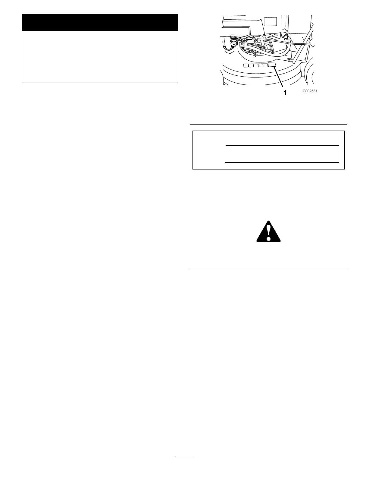
Figure1
1.Modelandserialnumberplate
ModelNo.
SerialNo.
Thismanualidentiespotentialhazardsandhas
safetymessagesidentiedbythesafetyalertsymbol
(Figure2),whichsignalsahazardthatmaycauseserious
injuryordeathifyoudonotfollowtherecommended
precautions.
Introduction
Readthisinformationcarefullytolearnhowtooperate
andmaintainyourproductproperlyandtoavoidinjury
andproductdamage.Youareresponsibleforoperating
theproductproperlyandsafely.
YoumaycontactTorodirectlyatwww .Toro.comfor
productandaccessoryinformation,helpndinga
dealer,ortoregisteryourproduct.
Wheneveryouneedservice,genuineToroparts,or
additionalinformation,contactanAuthorizedService
DealerorToroCustomerServiceandhavethemodel
andserialnumbersofyourproductready .Figure1
identiesthelocationofthemodelandserialnumbers
ontheproduct.Writethenumbersinthespace
provided.
Figure2
1.Safetyalertsymbol
Thismanualuses2wordstohighlightinformation.
Importantcallsattentiontospecialmechanical
informationandNoteemphasizesgeneralinformation
worthyofspecialattention.
©2008—TheToro®Company
8111LyndaleAvenueSouth
Bloomington,MN55420
Contactusatwww.Toro.com.
2
PrintedintheUSA
AllRightsReserved
Page 3

Contents
Safety
Introduction.................................................................2
Safety...........................................................................3
GeneralLawnMowerSafety.................................3
SafetyandInstructionalDecals.............................5
Setup............................................................................6
1InstallingtheHandle..........................................6
2InstallingtheFuelTankandtheFuel
Line..................................................................6
3FillingtheCrankcasewithOil.............................7
ProductOverview........................................................8
Controls...............................................................8
Operation.....................................................................9
CheckingtheEngineOilLevel..............................9
FillingtheFuelTankwithGasoline.......................9
StartingtheEngine.............................................11
StoppingtheEngine...........................................11
OperatingtheBlade............................................12
OperatingtheTractionDrive..............................12
CheckingtheBladeBrakeClutch........................13
AdjustingtheCuttingHeight..............................13
UsingtheGrassBag...........................................13
OperatingTips...................................................14
Maintenance...............................................................16
RecommendedMaintenanceSchedule(s)................16
Lubrication.............................................................16
LubricatingthePivotArms.................................16
LubricatingtheGearCase...................................17
EngineMaintenance...............................................17
ServicingtheAirFilter........................................17
ChangingtheEngineOil....................................18
ChangingtheOilFilter.......................................18
ServicingtheSparkPlug.....................................19
FuelSystemMaintenance.......................................20
EmptyingtheFuelTankandCleaningthe
FuelFilter.......................................................20
DriveSystemMaintenance.....................................20
AdjustingtheSelf-propelDrive...........................20
ServicingtheWheels..........................................20
ControlsSystemMaintenance.................................21
AdjustingtheBladeBrakeCable.........................21
BladeMaintenance.................................................23
MaintainingtheCuttingBlade.............................23
Cleaning.................................................................24
CleaningundertheMowerHousing....................24
CleaningtheBladeBrakeClutchShield...............25
Storage.......................................................................26
PreparingtheFuelSystem...................................26
PreparingtheEngine..........................................26
GeneralInformation..........................................26
RemovingtheLawnMowerfromStorage............26
Troubleshooting.........................................................27
ThislawnmowermeetsorexceedstheCPSC
bladesafetyrequirementsforwalk-behindrotary
lawnmowersandtheB71.4specicationsofthe
AmericanNationalStandardsInstituteineffectat
thetimeofproduction.
Improperlyusingormaintainingthislawnmower
canresultininjury.T oreducethepotentialfor
injury,complywiththesesafetyinstructions.
Torodesignedandtestedthislawnmowerfortooffer
reasonablysafeservice;however,failuretocomply
withthefollowinginstructionsmayresultin
personalinjury.
Engineexhaustcontainscarbonmonoxide,an
odorless,deadlypoisonthatcankillyou.
Donotruntheengineindoorsorinanenclosed
area.
Toensuremaximumsafety,bestperformance,and
togainknowledgeoftheproduct,itisessentialthat
youandanyotheroperatorofthelawnmowerread
andunderstandthecontentsofthismanualbefore
theengineiseverstarted.Payparticularattention
tothesafetyalertsymbol(Figure2)whichmeans
Caution,Warning,orDanger—“personalsafety
instruction.”Readandunderstandtheinstruction
becauseithastodowithsafety.Failuretocomply
withtheinstructionmayresultinpersonalinjury.
GeneralLawnMowerSafety
Thislawnmoweriscapableofamputatinghandsand
feetandofthrowingobjects.Failuretoobservethe
followingsafetyinstructionscouldresultinserious
injuryordeath.
ThefollowinginstructionsarefromtheANSI/OPEI
B71.4-2004standard.
Training
•ReadtheOperator’sManualandothertraining
material.Iftheoperator(s)ormechanic(s)cannot
readEnglishitistheowner’ sresponsibilitytoexplain
thismaterialtothem.
•Becomefamiliarwiththesafeoperationofthe
equipment,operatorcontrols,andsafetysigns.
•Alloperatorsandmechanicsshouldbetrained.The
ownerisresponsiblefortrainingtheusers.
3
Page 4

•Neverletchildrenoruntrainedpeopleoperateor
servicetheequipment.Localregulationsmayrestrict
theageoftheoperator.
•Theowner/usercanpreventandisresponsiblefor
accidentsorinjuriesoccurringtothemselves,other
people,orproperty.
includingemptyingthecatcheroruncloggingthe
chute.
•Stopequipmentandinspectbladeafterstriking
objectsorifanabnormalvibrationoccurs.Make
necessaryrepairsbeforeresumingoperations.
•Keephandsandfeetawayfromthecuttingunits.
Preparation
•Onlyuseaccessoriesandattachmentsapprovedby
themanufacturer.
•Wearappropriateclothingincludinghardhat,safety
glasses,andearprotection.Longhair,looseclothing
orjewelrymaygettangledinmovingparts.
•Inspecttheareawheretheequipmentistobeused
andremoveallobjectssuchasrocks,toysandwire
whichcanbethrownbythemachine.
•Useextracarewhenhandlinggasolineandother
fuels.Theyareammableandvaporsareexplosive.
–Useonlyanapprovedcontainer.
–Neverremovegascaporaddfuelwithengine
running.Allowenginetocoolbeforerefueling.
Donotsmoke.
–Neverrefuelordrainthemachineindoors.
•Checkthatoperator’spresencecontrols,safety
switchesandshieldsareattachedandfunctioning
properly.Donotoperateunlesstheyarefunctioning
properly.
Operation
•Neverrunanengineinanenclosedarea.
•Onlyoperateingoodlight,keepingawayfromholes
andhiddenhazards.
•Onlystartenginefromtheoperator’sposition.
•Besureofyourfooting,especiallywhenbacking
up.Walk,don’trun.Neveroperateonwetgrass.
Reducedfootingcouldcauseslipping.
•Slowdownanduseextracareonhillsides.Besure
totravelsidetosideonhillsides.Turfconditions
canaffectthemachine’ sstability.Usecautionwhile
operatingneardrop-offs.
•Donotoperatethelawnmowerwithouteitherthe
grasscatcherortheguardinplace.
•Donotchangetheenginegovernorsettingor
overspeedtheengine.
•Lookbehindanddownbeforebackinguptobesure
ofaclearpath.
•Keeppetsandbystandersaway.
•Slowdownandusecautionwhencrossingroadsand
sidewalks.Stopbladeifyouarenotmowing.
•Beawareofthemowerdischargedirectionanddo
notpointitatanyone.
•Donotoperatethemowerundertheinuenceof
alcoholordrugs.
•Usecarewhenloadingorunloadingthemachine
intoatrailerortruck.
•Usecarewhenapproachingblindcorners,shrubs,
trees,orotherobjectsthatmayobscurevision.
MaintenanceandStorage
•Stopengineanddisconnectsparkplugwire.Wait
forallmovementtostopbeforeadjusting,cleaning
orrepairing.
•Cleangrassanddebrisfromcuttingunit,drive,
mufer,andenginetohelppreventres.Cleanup
oilorfuelspillage.
•Letenginecoolbeforestoringanddonotstorenear
ame.
•Shutofffuelwhilestoringortransporting.Donot
storefuelnearamesordrainindoors.
•Neverallowuntrainedpersonneltoservicemachine.
•Removesparkplugwirebeforemakinganyrepairs.
•Usecarewhencheckingblade.Wrapthebladeor
weargloves,andusecautionwhenservicingthem.
Onlyreplaceblade.Neverstraightenorweldit.
•Keephandsandfeetawayfrommovingparts.If
possible,donotmakeadjustmentswiththeengine
running.
•Keepallpartsingoodworkingconditionandall
hardwaretightened.Replaceallwornordamaged
decals.
•Stoponlevelgroundandshutoffenginebefore
leavingtheoperator’spositionforanyreason
4
Page 5
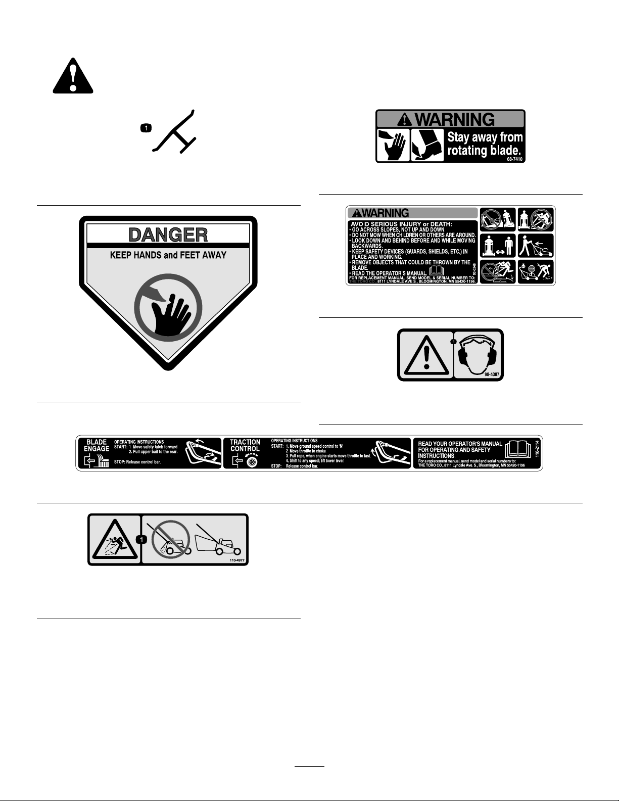
SafetyandInstructionalDecals
Safetydecalsandinstructionsareeasilyvisibletotheoperatorandarelocatednearanyareaof
potentialdanger.Replaceanydecalthatisdamagedorlost.
Manufacturer’sMark
1.Indicatesthebladeisidentiedasapartfromtheoriginal
machinemanufacturer.
43-8480
68-7410
93-0248
98-4387
1.Warning—wearhearingprotection.
110-4977
1.Thrownobjecthazard—donotoperatethemowerwithouta
baginplace.
110-2114
5
Page 6
Setup
LooseParts
Usethechartbelowtoverifythatallpartshavebeenshipped.
ProcedureDescription
Handle1
Bolt(5/16x7/8inch)
Bolt(5/16x1-1/2inches)
1
2
3
Washer4
Locknut(5/16inch)
Cabletie
Self-tappingscrew
Fueltank1
Nopartsrequired
Note:Determinetheleftandrightsidesofthemachine
fromthenormaloperatingposition.
1
InstallingtheHandle
Qty.
Use
2
2
4
3
2
–
Installthehandle.
Installthefueltankandfuelline.
Fillthecrankcasewithoil.
Partsneededforthisprocedure:
1Handle
2
Bolt(5/16x7/8inch)
2
Bolt(5/16x1-1/2inches)
4Washer
4
Locknut(5/16inch)
3
Cabletie
Procedure
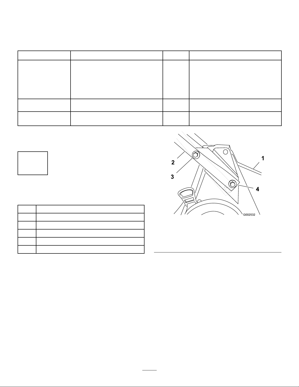
1.Mountthehandletothemowerhousingwith2bolts
(5/16x7/8inch),2bolts(5/16x1-1/2inches),4
washers,and4locknuts(Figure3).
Figure3
1.Housing
2.Handle
3.Bolt(5/16x1-1/2inches),
washer,andlocknut
4.Bolt(5/16x7/8inch),
washer,andlocknut
Note:Installthewasherswiththecupsidefacing
thehandle.
Note:Youcanadjustthehandleheightformore
comfortableoperation.Securingthelowerhandle
endintheupperholelowersthehandle;securingthe
lowerhandleendinthelowerholeraisesthehandle.
2.Usethecabletiesprovidedtosecurethecontrol
cablestothehandle.
6
Page 7
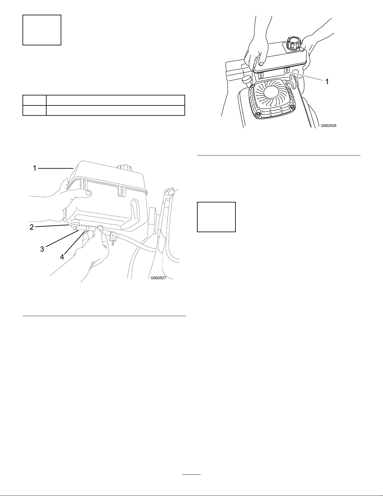
2
G002527
1
2
3
4
InstallingtheFuelTankand
theFuelLine
Partsneededforthisprocedure:
2
Self-tappingscrew
1Fueltank
Procedure
1.Slidetheendofthefuellineontotheelbowtting
(Figure4).
Figure4
1.Fueltank3.Fuelline
2.Elbowtting
2.Securethefuellineinplacewiththefuellineclamp
(Figure4).
4.Fuellineclamp
Figure5
1.Plasticclip(2)
4.Securethebottomofthefueltanktothefueltank
bracketbyinstallingtheself-tappingscrewsfromthe
bottom.Torquethescrewsto40to50in-lb(4.5
to5.6N-m).Donotovertightenthescrews.
3
FillingtheCrankcasewithOil
NoPartsRequired
Procedure
Theenginecrankcaseisshippedwithoutoil.Youmust
llitwithapproximately29oz.(0.85l)ofoilbefore
startingtheengine.RefertoCheckingtheEngineOil
Levelforoilspecicationsandinstructions.
3.Slidetheplasticclipsonthefrontofthefueltank
ontothefueltankmount(Figure5).
7
Page 8
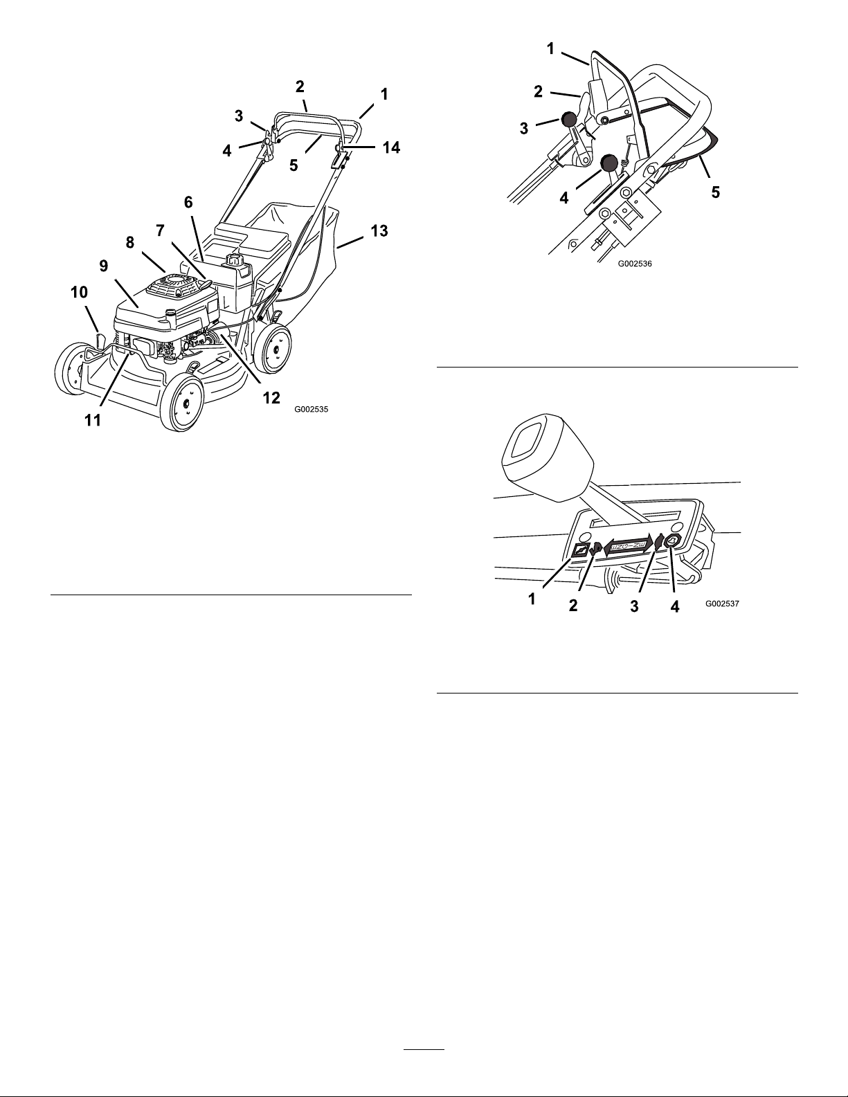
ProductOverview
Figure6
1.Handle
2.Bladecontrolbar
3.Controlbarlock10.Cuttingheightlever
4.Groundspeedcontrol
lever
5.Tractioncontrolbar
6.Fueltank
7.Starterhandle
8.Oilll/dipstick(notshown)
9.Airlter
11.Sparkplug
12.Oillter
13.Grassbag
14.Throttlecontrollever
Figure7
1.Bladecontrolbar4.Throttlecontrollever
2.Controlbarlock
3.Groundspeedcontrol
lever
5.Tractioncontrolbar
Thethrottlesettingsareshownin(Figure8).
Controls
Thebladecontrolbar,controlbarlock,groundspeed
controllever,throttlecontrollever,andtractioncontrol
barareontheupperhandleasshownin(Figure7).
Figure8
1.Choke3.Slow
2.Fast
4.Stop
8
Page 9
Operation
Note:Determinetheleftandrightsidesofthe
machinefromthenormaloperatingposition.
Note:Whenthecrankcaseisempty,pourabout3/4
ofthecrankcasecapacityofoilinthecrankcase,then
followtheprocedureinthissection.
1.Movethelawnmowertoalevelsurface.
Eachtimebeforeyoumow ,makesurethatthe
self-propeldriveandthebladecontrolbaroperate
properly.Whenyoureleasethebladecontrolbar,the
bladeshouldstop.Ifitdoesnot,contactanAuthorized
ServiceDealer.
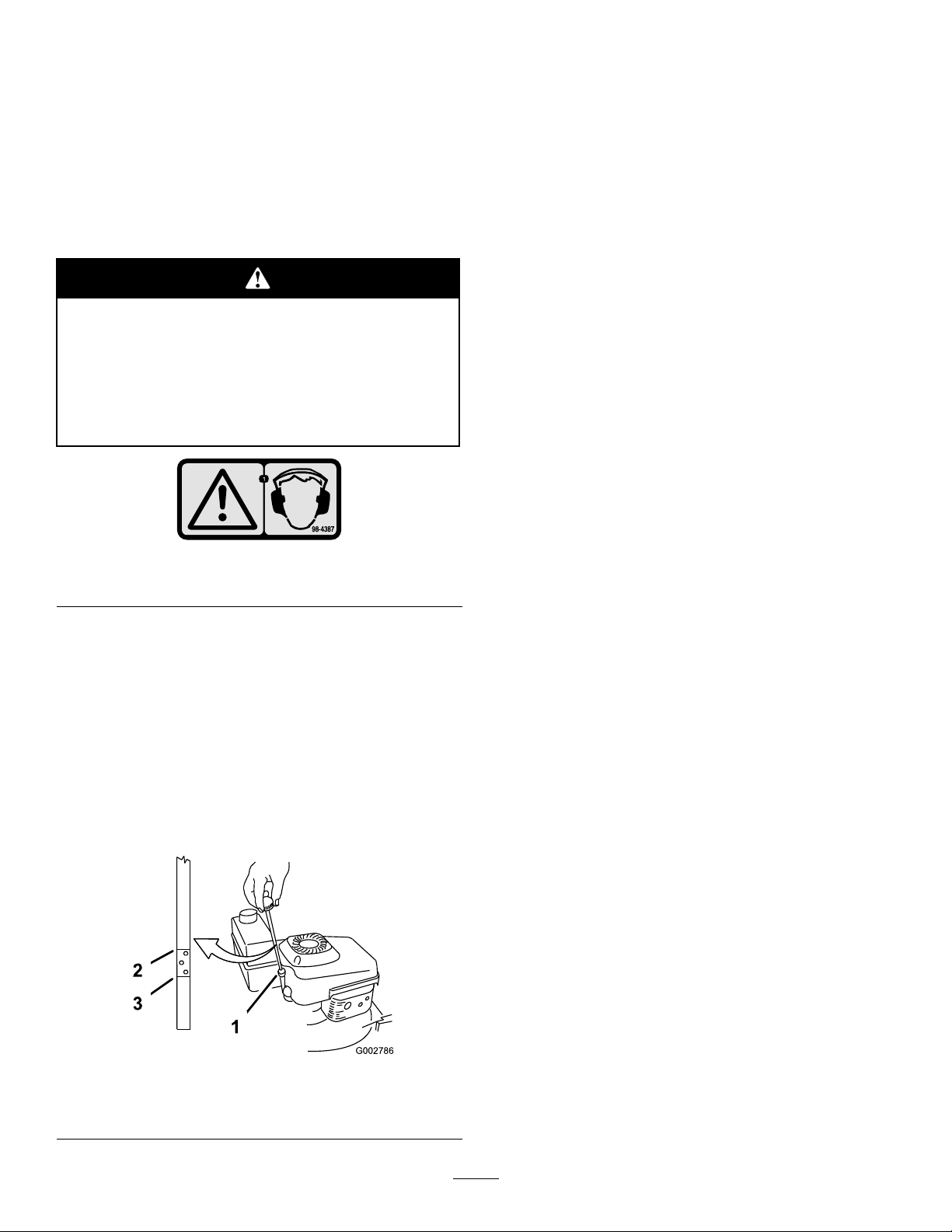
Thismachineproducessoundlevelsinexcess
of85dBAattheoperator’searandcancause
hearinglossthroughextendedperiodsof
exposure.
Wearhearingprotectionwhenoperatingthis
machine.
Figure9
1.Warning—wearhearingprotection.
2.Cleanaroundthedipstick(Figure10).
3.Removethedipstickbyrotatingthecap
counterclockwiseandpullingitout.
4.Wipethedipstickcleanwithacleancloth.
5.Insertthedipstickintothellerneck,butdonot
screwitin.
6.Removethedipstickandreadtheoillevelonthe
dipstick(Figure10).
7.IftheoillevelreadingisbelowtheAddmarkon
thedipstick,slowlypouronlyenoughoilintothe
llerholetoraisetheoilleveltotheFullmarkon
thedipstick.
Important:Donotoverllthecrankcasewith
oilandruntheengine;enginedamagewill
result.Draintheexcessoiluntiltheoillevelon
thedipstickreadsFull.
8.Insertthedipstickintothellerneckandrotatethe
capclockwiseuntilitistight.
CheckingtheEngineOilLevel
ServiceInterval:Beforeeachuseordaily
Initially,llthecrankcasewith29ounces(0.85liters)
ofoil.Useonlyhigh-qualitySAE30orSAE10W30
weightdetergentoilthathastheAmericanPetroleum
Institute(API)serviceclassicationSF ,SG,SH,orSJ.
Beforeeachuse,ensurethattheoillevelisbetweenthe
AddandFullmarksonthedipstick(Figure10).
Figure10
1.Dipstick3.Add
2.Full
FillingtheFuelTankwith
Gasoline
Forbestresults,useclean,fresh,lead-freegasolinewith
anoctaneratingof87orhigher.T oensurefreshness,
purchaseonlythequantityofgasolinethatyouexpectto
usein30days.Usingunleadedgasolineresultsinfewer
combustiondepositsandlongerenginelife.Youmay
useleadedgasolineifunleadedgasolineisnotavailable.
Important:Donotaddoiltothegasoline.
Important:Donotusemethanol,gasoline
containingmethanol,gasoholcontainingmore
than10%ethanol,premiumgasoline,orwhitegas.
Usingthesefuelscandamagetheengine’sfuel
system.
Important:Donotusegasolinethathasbeen
storedsincethelastmowingseasonorlonger.
9
Page 10

Incertainconditions,gasolineisextremely
ammableandhighlyexplosive.Areor
explosionfromgasolinecanburnyouand
othersandcandamageproperty.
Whenfueling,undercertaincircumstances,a
staticchargecandevelop,ignitingthegasoline.
Areorexplosionfromgasolinecanburnyou
andothersanddamageproperty.
•Fillthefueltankoutdoors,inanopenarea,
andwhentheengineiscold.Wipeupany
gasolinethatspills.
•Donotllthefueltankcompletelyfull.Add
gasolinetothefueltankuntilthelevelis1/4
to1/2inch(6to13mm)belowthebottomof
thellerneck.Thisemptyspaceinthetank
allowsthegasolinetoexpand.
•Neversmokewhenhandlinggasoline,and
stayawayfromanopenameorwherea
sparkmayignitethegasolinefumes.
•Storegasolineinanapprovedfuelcontainer
andkeepitoutofthereachofchildren.
•Neverbuymorethana30-daysupplyof
gasoline.
•Alwaysplacegasolinecontainersonthe
groundandawayfromyourvehiclebefore
lling.
•Donotllgasolinecontainersinsidea
vehicleoronatruckortrailerbedbecause
interiorcarpetsorplastictruckbedliners
mayinsulatethecontainerandslowtheloss
ofanystaticcharge.
•Whenpractical,removegasoline-powered
equipmentfromthetruckortrailerand
refueltheequipmentwithitswheelsonthe
round.
•Ifthisisnotpossible,thenrefuelsuch
equipmentonatruckortrailerfroma
portablecontainer,notfromagasoline
dispensernozzle.
•Ifyoumustuseagasolinedispensernozzle,
keepthenozzleincontactwiththerimof
thefueltankorcontaineropeningatall
timesuntilfuelingiscomplete.
Useafuelstabilizer/conditionerregularlyduring
operationandstorage.Astabilizer/conditionercleans
theengineduringoperationandpreventsgum-like
varnishdepositsfromformingintheengineduring
periodsofstorage.
Important:Donotusefueladditivesotherthan
afuelstabilizer/conditioner.Donotusefuel
stabilizerswithanalcoholbasesuchasethanol,
methanol,orisopropanol.
1.Cleanaroundthefueltankcap(Figure11).
10
Page 11

1.Oilll/dipstick
2.Fueltankcap
StartingtheEngine
1.Connectthewiretothesparkplug(Figure12).
Figure12
1.Spark-plugwire
2.Openthefuelvalve(Figure13)
Figure11
3.Aircleaner
2.Removethecapfromthetank.
3.Fillthefueltankwithunleadedgasolinetowithin
1/4to1/2inch(6to13mm)fromthetopofthe
tank.Donotllintothellerneck.
Important:Donotllthetankmorethan1/4
inch(6mm)fromthetopofthetankbecause
thegasolinemusthaveroomtoexpand.
4.Installthefueltankcapandwipeupanyspilled
gasoline.
Figure13
1.Fuelvalve
3.MovethethrottlecontrollevertotheChoke
position(Figure8).
4.MovethegroundspeedcontrollevertotheNeutral
(N)position.
5.Pullthestarterhandlelightlyuntilyoufeel
resistance,thenpullitsharply.
6.Regulatethethrottleandthegroundspeedcontrol
asdesiredwhentheenginestarts.
Note:Iftheenginefailstostartafter3pulls,repeat
steps3through6.
StoppingtheEngine
1.MovethethrottlecontroltotheStopposition.
2.Disconnectthewirefromthesparkplugifyoudo
notusethelawnmowerorleaveitunattended.
11
Page 12

OperatingtheBlade
OperatingtheTractionDrive
EngagingtheBlade
Whenyoustartyourengine,thebladedoesnotturn.
Youmustengagethebladetomow .
1.Pushthecontrolbarlockforward(Figure14).
Figure14
EngagingtheTractionDrive
1.Releasethetractioncontrolbar(Figure16).
Figure16
2.Movethegroundspeedcontrollevertothedesired
gearposition.
2.Pullthebladecontrolbartothehandleandhold
it(Figure15).
Figure15
DisengagingtheBlade
3.Squeezethetractioncontrolbaragainstthehandle
(Figure17).
Figure17
DisengagingtheTractionDrive
Releasethebladecontrolbar.
Important:Whenyoureleasethebladecontrol
bar,thebladeshouldstopwithin3seconds.Ifit
doesnotstopproperly,stopusingyourmower
immediatelyandcontactanAuthorizedService
Dealer.
Releasethetractioncontrolbar.
12
Page 13

CheckingtheBladeBrake
Clutch
Checkthebladecontrolbarbeforeeachusetoensure
thatthebladebrakeclutchsystemisoperatingproperly.
1.Installtheemptygrassbagonthedischargetunnel.
2.Starttheengine.
3.Pullthebladecontrolbartothenormalblade
engagedposition.Thebagshouldbegintoinate,
indicatingthatthebladeisengagedandrotating.
4.Releasethebladecontrolbar.Ifthebagdoesnot
immediatelydeate,itindicatesthattheblade
isstillrotating.Thebladebrakeclutchmaybe
deteriorating,and,ifignored,couldresultinan
unsafeoperatingcondition.Havethelawnmower
inspectedandservicedbyanAuthorizedService
Dealer.
Ifthebladebrakeclutchsystemisinoperative,
thebladewillcontinuetorotatewhenyou
releasethebladecontrolbail.Contactwith
bladecouldoccur,causingseriousinjury.
•Checkthebladebrakeclutchoperation
beforeeachuse.
Adjustingthecuttingheightleverscouldbring
yourhandsintocontactwithamovingblade
andresultinseriousinjury.
•Stoptheengineandwaitforallmovement
tostopbeforeadjustingthecuttingheight.
•Donotputyourngersunderthehousing
whenadjustingthecuttingheight.
1.Pullthewheelheightadjustmentlevertowardthe
wheel(Figure18)andmoveittothedesiredsetting.
Figure18
1.Wheelheightadjustmentlever
•Neveruseamowerequippedwithablade
brakeclutchthathasaninoperativesafety
system.
•TakeyourmowertoanAuthorizedService
Dealerforrepairifthesafetysystemfailsto
operateproperly.
AdjustingtheCuttingHeight
Eachwheelisadjustedindividuallywithawheelheight
adjustmentlever.Cuttingheightsare1-1/4inches(32
mm),1-3/4inches(44mm),2-1/4inches(57mm),
2-3/4inches(70mm),3-1/4inches(83mm),and
3-3/4inches(95mm).
2.Releasethewheelheightadjustmentleverandseat
itsecurelyinthenotch.
3.Adjustallthewheelstothesamecuttingheight
setting.
UsingtheGrassBag
InstallingtheGrassBag
1.Waitforallmovingpartstostop.
2.Raiseandholdupthereardoor(Figure19).
13
Page 14

MowingwiththeGrassBag
Aworngrassbagcouldallowsmallstones
andothersimilardebristobethrowninthe
operator’sorbystander’sdirectionandresultin
seriouspersonalinjuryordeathtotheoperator
orbystanders.
Checkthegrassbagfrequently.Ifitis
damaged,installanewTororeplacementbag.
Figure19
1.Reardoor
3.Installthebagonthebagmountingposts
(Figure20).
Figure20
1.Bagmountingposts
OperatingTips
GeneralTips
•Maintainasharpbladethroughoutthecutting
season.Periodicallyledownnicksontheblade.
•Replacethebladewhennecessarywithanoriginal
Tororeplacementblade.
•Mowonlydrygrassorleaves.Wetgrassandleaves
tendtoclumpontheyardandcancausethemower
toplugortheenginetostall.
Wetgrassorleavescancauseseriousinjuryif
youslipandcontacttheblade.
Mowonlyindryconditions.
•Cleanunderthemowerhousingaftereachmowing.
SeeCleaningundertheMowerHousing.
4.Lowerthereardoor.
RemovingtheGrassBag
Toremovethebag,reversethestepsabove.
Themowercanthrowgrassclippingsandother
objectsthroughanopendischargetunnel.
Objectsthrownwithenoughforcecouldcause
seriouspersonalinjuryordeathtotheoperator
orbystander.
Donotoperatethemowerwithoutagrassbag
installed.
•Keeptheengineingoodrunningcondition.
•Settheenginespeedtothefastestpositionforthe
bestcuttingresults.
14
Page 15

•Forlightleafcoverage,setallthewheelsatthesame
cuttingheightsetting.
Operatingamowerwithitsenginerunningat
aspeedgreaterthanthefactorysettingcan
causethemowertothrowapartofthebladeor
engineintotheoperator’sorbystander’sarea
andresultinseriouspersonalinjuryordeath.
–Donotchangetheenginespeedsetting.
–Ifyoususpecttheenginespeedisfaster
thannormal,contactanAuthorizedService
Dealer.
•Cleantheairlterfrequently.Mulchingstirsup
moreclippingsanddustwhichclogstheairlter
andreducesengineperformance.
CuttingGrass
•Grassgrowsatdifferentratesatdifferenttimesof
theyear.Inthesummerheat,itisbesttocutgrass
atthe2-1/4inch(57mm),2-3/4inch(70mm),or
3-1/4inch(83mm)cuttingheightsettings.Cut
onlyaboutathirdofthegrassbladeatatime.Do
notcutbelowthe2-1/4inch(57mm)settingunless
thegrassissparseoritislatefallwhengrassgrowth
beginstoslowdown.
•Whencuttinggrassover6inches(15cm)tall,rst
mowatthehighestcuttingheightsettingandwalk
slower;thenmowagainatalowersettingforthe
bestlawnappearance.Ifthegrassistoolongand
theleavesclumpontopofthelawn,themowermay
plugandcausetheenginetostall.
•Alternatethemowingdirection.Thishelpsdisperse
theclippingsoverthelawnforevenfertilization.
•Iftherearemorethan5inches(12.7cm)ofleaves
onthelawn,setthefrontcuttingheight1or2
notcheshigherthantherearcuttingheight.This
makesiteasiertofeedtheleavesunderthemower
housing.
•Slowdownyourmowingspeedifthemowerdoes
notcuttheleavesnelyenough.
•Ifyoumowoveroakleaves,youcanaddlimeto
thegrassinthespringtoreducetheacidityofthe
oakleaves.
Ifthenishedlawnappearanceisunsatisfactory,try
oneormoreofthefollowing:
•Sharpentheblade.
•Walkataslowerpacewhilemowing.
•Raisethecuttingheightonyourmower.
•Cutthegrassmorefrequently .
•Overlapcuttingswathsinsteadofcuttingafull
swathwitheachpass.
•Setthecuttingheightonthefrontwheelsonenotch
lowerthantherearwheels.Forexample,setthe
frontwheelsat2-1/4inches(57mm)andtherear
wheelsat2-3/4inches(70mm).
CuttingLeaves
•Aftercuttingthelawn,ensurethathalfofthelawn
showsthroughthecutleafcover.Youmayneedto
makemorethanonepassovertheleaves.
15
Page 16

Maintenance
Note:Determinetheleftandrightsidesofthemachinefromthenormaloperatingposition.
RecommendedMaintenanceSchedule(s)
MaintenanceService
Interval
Aftertherst8hours
Beforeeachuseordaily
Every25hours
Every50hours
Every100hours
Every300hours
Yearly
Important:Refertoyour
MaintenanceProcedure
•Changetheengineoil.
•Checktheengineoillevel.
•Inspectthemowerbladesforwearordamage.
•Cleanunderthemowerhousing.
•Cleanthefoampre-cleaner(morefrequentlyindustyconditions).
•Lubricatethepivotarms.
•Changetheengineoil(moreoftenindustyconditions).
•Cleanthebladebrakeclutchshield.
•Lubricatethegearcase.
•Changetheoillter.
•Checkthesparkplug.
•Replacethepaperairlter(morefrequentlyindustyconditions).
•Emptythefueltankandcleanthefuellter.
Engine Operator’ s Man ual
foradditionalmaintenanceprocedures.
Ifyouleavethewireonthesparkplug,someonecouldaccidentlystarttheengineandseriouslyinjure
youorotherbystanders.
Disconnectthewirefromthesparkplugbeforeyoudoanymaintenance.Setthewireasidesothatit
doesnotaccidentlycontactthesparkplug.
Lubrication
LubricatingthePivotArms
ServiceInterval:Every50hours
1.Movetherearwheelcuttingheightleverstothe
centersetting.
2.Wipethegreasettingswithacleanrag(Figure21).
3.Installagreasegunontothettingandgentlyapply2
or3pumpsof#2multi-purposelithium-basegrease.
Important:Excessivegreasepressuremay
damagetheseals.
Figure21
16
Page 17

LubricatingtheGearCase
ServiceInterval:Every100hours
1.Removethegrassbag.
2.Installagreasegunontothettingthroughthebelt
coveropening(Figure22).
Figure22
EngineMaintenance
ServicingtheAirFilter
ServiceInterval:Every25hours—Cleanthefoam
pre-cleaner(morefrequentlyindusty
conditions).
Every300hours—Replacethepaper
airlter(morefrequentlyindusty
conditions).
Important:Donotoperatetheenginewithoutthe
airlterassembly;extremeenginedamagewill
occur.
1.Stoptheengineandwaitforallmovingpartstostop.
2.Disconnectthewirefromthesparkplug(Figure12).
3.Removethescrewthatsecurestheaircleanercover
(Figure23).
3.Gentlyapplyoneto2pumpsof#2multi-purpose
lithium-basegrease.
4.Installthegrassbag.
Figure23
1.Screw3.Paperairlter
2.Cover
4.Removethecoverandcleanitthoroughly(Figure23).
5.Removeandinspectthepaperairlter(Figure24),
anddiscarditifitisexcessivelydirty.
17
Figure24
1.Paperairlter
Important:Donottrytocleanapaperlter.
2.Foampre-cleaner
Page 18

6.Removethefoampre-cleanerandwashitwitha
milddetergentandwater,thenblotitdry.
7.Saturatethepre-cleanerwithoil,thensqueezeit(do
nottwist)toremovetheexcessoil.
8.Installthefoampre-cleaner.
9.Installthepaperairlter.
Note:Installanewpaperairlterifyoudiscarded
theoldone.
10.Installthecoverandsecureitwiththescrew.
ChangingtheOilFilter
ServiceInterval:Every100hours
ChangingtheEngineOil
ServiceInterval:Aftertherst8hours
Every50hours
OilCapacity
Withoillter29ounces(0.85liters)
Withoutoillter22ounces(0.65liters)
1.Runtheenginetowarmtheengineoil.
Note:W armoilowsbetterandcarriesmore
contaminants.
Oilmaybehotafterenginehasbeenrun,and
contactwithhotoilcancauseseverepersonal
injury.
Avoidcontactingthehotengineoilwhenyou
drainit.
2.Stoptheengineandwaitforallmovingpartstostop.
3.Disconnectthewirefromthesparkplug(Figure12).
4.Placeasuitabledrainpanundertherightsideof
themower.
Figure25
1.Oillter
2.Fuelline
1.Runtheenginetowarmtheoil.
Oilmaybehotaftertheenginehasbeenrun,
andcontactwithhotoilcancausesevere
personalinjury.
Avoidcontactingthehotengineoilwhenyou
drainit.
2.Stoptheengineandwaitforallmovingpartstostop.
3.Disconnectthewirefromthesparkplug(Figure12).
4.Draintheengineoil;refertoChangingtheEngine
Oil.
5.Placearagundertheoilltertocatchanyoilthat
mayleakoutasyouremovethelter(Figure25).
6.Removetheoillter.
7.Useyourngertocoatthegasketonthenewlter
withoil(Figure26).
5.Removethedipstickbyrotatingthecap
counterclockwiseandpullingitout.
6.Tipthemowerontoitsrightsidetodraintheoil
intothedrainpan.
Note:Youcanalsoremovetheoilfromthe
crankcaseusinganoilextractor.
7.Returnthemowertoitsoperatingposition.
8.Insertthedipstickintothellerneckandrotatethe
capclockwiseuntilitistight.
9.Recycletheusedoilaccordingtolocalcodes.
10.FillthecrankcasetotheFulllineonthedipstickwith
freshoil.RefertotheFillingtheCrankcasewithOil.
11.Wipeupanyspilledoil.
18
Page 19

Figure27
Figure26
1.Gasket
1.Centerelectrodeinsulator
2.Sideelectrode
3.Airgap(nottoscale)
8.Installthenewlterandhandtightenit2/3turn
only.
9.FillthecrankcasetotheFulllineonthedipstickwith
freshoil.RefertoFillingtheCrankcasewithOil.
10.Connectthewiretothesparkplug.
11.Runtheengineforabout3minutes.
12.Stoptheengine,waitforallmovingpartstostop,
andcheckforoilleakagearoundthelter.
13.Addoiltocompensatefortheoilintheoillter.
RefertoCheckingtheEngineOilLevel.
14.Recycletheusedoillteraccordingtolocalcodes.
ServicingtheSparkPlug
ServiceInterval:Every100hours
UseanNGKBPR5ESsparkplugorequivalent.
1.Stoptheengineandwaitforallmovingpartstostop.
2.Disconnectthewirefromthesparkplug(Figure12).
6.Installthesparkplugandthegasketseal.
7.Torquetheplugto17ft-lb(23N⋅m).
8.Connectthewiretothesparkplug.
3.Cleanaroundthesparkplug.
4.Removethesparkplugfromthecylinderhead.
Important:Replaceacracked,fouled,or
dirtysparkplug.Donotcleantheelectrodes
becausegritenteringthecylindercandamage
theengine.
5.Setthegapontheplugto0.030inch(0.76mm)
(Figure27).
19
Page 20

FuelSystem
DriveSystem
Maintenance
EmptyingtheFuelTankand
CleaningtheFuelFilter
ServiceInterval:Yearly
Thefuellter(screen)elementislocatedinsidethefuel
tank.
1.Stoptheengineandwaitforittocooldown.
Note:Draingasolinefromacoldengineonly .
2.Disconnectthewirefromthesparkplug.
3.Disconnectthefuellinebylooseningthetubeclamp
atthecarburetor.
4.Openthefuelvalve.
5.Drainthegasolinecompletelyfromthetankandfuel
lineintoanapprovedfuelcontainer.
6.Removethefueltankfromthemower.
Maintenance
AdjustingtheSelf-propelDrive
Ifthemowerdoesnotself-propelorhasatendencyto
creepforwardwhenthecontrolbarismorethan1-1/2
inches(3.8cm)fromthehandle,adjusttheself-propel
drive.
1.Loosenthenutthatsecurestheturnbuckle
(Figure28).
7.Pourasmallamountoffuelinthefueltank,move
thefuelaroundinthetank,andpouritoutintoan
approvedfuelcontainer.
8.Installthefueltankandfuelline;refertoInstalling
theFuelTankandtheFuelLine.
Figure28
1.Turnbuckle
2.Nut
2.Turntheturnbuckleuntilyouremovetheslackin
theexposedcable(Figure28).
3.Tightenthenut.
Note:Tochecktheadjustment,slowlypullthe
mowerbackwardwhileyougraduallymovethe
controlbartowardthehandle.Theadjustmentis
correctwhentherearwheelsstopturningandthe
topofthecontrolbarisabout1-1/2inches(3.8cm)
fromthehandle.
3.Cable
4.1-1/2inches(3.8cm)
ServicingtheWheels
RemovingtheWheels
1.Stoptheengineandwaitforallmovingpartstostop.
2.Disconnectthewirefromthesparkplug(Figure12).
3.Removethebolt,thewheelspacer,andthelocknut
mountingthewheeltothepivotarm(Figure29).
20
Page 21

ControlsSystem
Maintenance
AdjustingtheBladeBrake
Cable
Figure29
1.Locknuts
2.Wheelspacer7.Lug
3.Bearing/hubassembly8.Bearing(2)
4.Bearingspacer9.Bolt
5.Wheelhalf
4.Separatethewheelhalvesfromthetirebyremoving
4boltsand4locknuts(Figure29).
Note:Ifyouremovethebearingsfromthe
bearing/hubassembly,removethembypressingon
thebearingspacer(Figure29).
6.Plasticcover(rearwheels
only)
AssemblingtheWheels
1.Positionthetireontoonewheelhalf,aligningthe
lugsoneach(Figure29).
2.Placethebearing/hubassemblyintothecenterhole
ofthewheelhalf.Ensurethatthelegsofthehubare
positionedovertheangeofthehole(Figure29).
Wheneveryouinstallanewbladebrakecableorreplace
thebladebrakeassembly,adjustthespringtensionon
thebladebrakecable.
1.Stoptheengineandwaitforallmovingpartstostop.
2.Disconnectthewirefromthesparkplug(Figure12).
3.Removethefueltankfromthetankbracket.
Note:Youdonotneedtodisconnectthefuelline
fromthefueltank.
4.Resetthecableadjusteronthehandlesothat1/4
inch(6mm)ofthethreadsshow ,thentightenthe
nut(Figure30).
3.Placetheotherwheelhalfontothebearing/hub
assembly,aligningthewheelandthetirelugsandthe
mountingholes(Figure29).
4.Using2fullythreadedscrewsorbolts(1/4-20x1.50
inch)andnon-lockingnuts,looselysecurethewheel
halvestogether.Mountthescrewsorboltsinthe
opposingholes(Figure29).
5.Checkthealignmentofallpartsandtightenthe
screws,alternatingfromsidetosideforauniformt,
untilthewheelhalvesaredrawntogether(Figure29).
6.Installthe2boltsand2locknutspreviouslyremoved
intheremainingholesinthewheelhalvesand
tighten.Removethe2longscrewsorboltsand
replacethemwith2boltsand2locknuts(Figure29).
7.Installthewheeltothepivotarmwiththebolts,
aspacer,andalocknut.Ensurethatthespaceris
positionedbetweenthewheelhubandthepivotarm
(Figure29).
Figure30
1.Cableadjuster3.1/4inch(6mm)ofthreads
2.Nut
5.Loosenthecableclampscrewuntilthebrakecable
conduitslides(Figure31).
21
Page 22

Figure31
1.Spring3.Cableclampscrew
2.Brakecableconduit
6.Holdthebladecontrolbarsothattheoutsideofthe
baris5-1/2inches(14cm)fromtheoutsideofthe
handle,andpullthecabletotheremovetheslack,
butdonotputtensiononthespring(Figure32).
toadjustthecableadjustertoachievethisvalue
(Figure30).
Donotovertightenthebladebrakecable.
Overtighteningthebladebrakecablecould
preventthebladebrakefromcontactingthe
brakedrumwhenyoureleasethecontrolbar.
Ifthebladebrakedoesnotcontactthebrake
drum,thebladewillnotstoprotating,which
couldcauseseriouspersonalinjury.
•Eachtimeyouadjustthebrakecable,ensure
thatthebrakestopsthebladein3seconds
orless.
•Ifthebladedoesnotstoprotatingin3
secondsorless,bringthemowertoan
AuthorizedServiceDealerforinspection
andrepair.
Figure32
1.5-1/2inches(14cm)
2.Handle
3.Bladecontrolbar
7.Torquethecableclampscrewto100to120in-lb(11
to14N-m)tolocktheadjustmentinplace.
8.Measurethelengthofthespringbothbeforeand
afterengagingthebladecontrolbar.Thedifference
betweenthese2lengthsisthespringstretch.
Note:Thespringstretchmustbebetween0.290
and0.310inches(7.4to7.9mm).Youmayneed
22
Page 23

BladeMaintenance
MaintainingtheCuttingBlade
Alwaysmowwithasharpblade.Asharpbladecuts
cleanlyandwithouttearingorshreddingthegrassblades.
1.Stoptheengineandwaitforallmovingpartstostop.
2.Disconnectthewirefromthesparkplug(Figure12).
3.Drainthegasolinefromthefueltank;referto
EmptyingtheFuelTankandCleaningtheFuelFilter.
4.Tipthemowerontoitsrightside(Figure33).
Figure33
1.Blade3.Anti-scalpcup
2.Bladenuts
InspectingtheBlade
Figure34
1.Sail
2.Flatpartoftheblade4.Slotformed
3.Wear
Note:Forthebestperformance,installanewblade
beforethecuttingseasonbegins.Duringtheyear,le
downanysmallnickstomaintainthecuttingedge.
Awornordamagedbladecanbreak,anda
pieceofthebladecouldbethrownintothe
operator’sorbystander’sarea,resultingin
seriouspersonalinjuryordeath.
•Inspectthebladeperiodicallyforwearor
damage.
•Replaceawornordamagedblade.
RemovingtheBlade
Grasptheendofthebladeusingaragorathickly
paddedglove.Removethebladenuts,theanti-scalpcup,
andtheblade(Figure33).
ServiceInterval:Beforeeachuseordaily
Carefullyexaminethebladeforsharpnessandwear,
especiallywheretheatandthecurvedpartsmeet
(Figure34A).Becausesandandabrasivematerialcan
wearawaythemetalthatconnectstheatandcurved
partsoftheblade,checkthebladebeforeusingthe
mower.Ifyounoticeaslotorwear(Figure34Band
Figure34C),replacetheblade;refertoRemovingthe
Blade.
SharpeningtheBlade
Filethetopsideofthebladetomaintainitsoriginal
cuttingangle(Figure35A)andinnercuttingedgeradius
(Figure35B).Thebladewillremainbalancedifyou
removethesameamountofmaterialfrombothcutting
edges.
Figure35
1.Sharpenatthisangleonly .
23
2.Maintaintheoriginalradius
here.
Page 24

BalancingtheBlade
1.Checkthebalanceofthebladebyplacingthecenter
holeofthebladeoveranailorscrewdrivershank
clampedhorizontallyinavise(Figure36).
Figure36
Note:Youcanalsocheckthebalanceusinga
commerciallymanufacturedbladebalancer.
2.Ifeitherendofthebladerotatesdownward,lethat
end(notthecuttingedgeortheendnearthecutting
edge).Thebladeisproperlybalancedwhenneither
enddrops.
InstallingtheBlade
Cleaning
CleaningundertheMower
Housing
Toensurethebestperformance,keeptheundersideof
themowerhousingclean.
WashingMethod
ServiceInterval:Beforeeachuseordaily
1.Positionthemoweronaatconcreteorasphalt
surfacenearagardenhose.
2.Starttheengine.
3.Holdtherunninggardenhoseathandleleveland
directthewatertoowonthegroundjustinfront
oftherightrearwheel(Figure37).
1.Installasharp,balancedToroblade,theanti-scalp
cup,andthebladenuts.Thesailoftheblademust
pointtowardthetopofthemowerhousingfor
properinstallation.Torquethebladenutsto23to
27ft-lb(32to37N-m).
2.Returnthemowertoitsoperatingposition.
3.Connectthewiretothesparkplug.
Figure37
1.Rightrearwheel
Note:Thebladewillsplashintothepathofthe
blade,cleaningouttheclippings.
4.Stoptheengineandwaitforallmovingpartstostop.
5.Turnoffthewater.
6.Startthemowerandletitrunforafewminutes
todryoutthemoistureonthemowerandits
components.
ScrapingMethod
Ifwashingdoesnotremovealldebrisfromunderthe
mower,scrapeitclean.
1.Disconnectthewirefromthesparkplug(Figure12).
2.Drainthefuelfromthefueltank.RefertoEmptying
theFuelTankandCleaningtheFuelFilter.
24
Page 25

Tippingthemowermaycausethefueltoleak
fromthecarburetororthefueltank.Gasoline
isextremelyammable,highlyexplosive,and,
undercertainconditions,cancausepersonal
injuryorpropertydamage.
Avoidfuelspillsbyrunningtheenginedryor
byremovingthegasolinewithahandpump;
neversiphon.
3.Tipthemowerontoitsrightside.
4.Removethedirtandgrassclippingswithahardwood
scraper.Avoidburrsandsharpedges.
5.Returnthemowertoitsoperatingposition.
6.Fillthefueltank.
7.Connectthewiretothesparkplug.
CleaningtheBladeBrake
ClutchShield
Figure38
1.Screws(4)
7.Removetheshieldandbrushorblowallthedebris
fromundertheshieldandaroundthebladebrake
clutchsystem.
8.Installtheshieldusingthe4screwsthatyou
previouslyremoved.
2.Bladebrakeclutchshield
ServiceInterval:Every50hours
Cleaninsidethebladebrakeclutchshieldwhenyou
changetheengineoilorwhenyousharpentheblade,
becauseyouneedtoremovethebladeinorderto
removetheshield.
1.Stoptheengineandwaitforallmovingpartstostop.
2.Disconnectthewirefromthesparkplug(Figure12).
3.Drainthegasolinefromthefueltank;referto
EmptyingtheFuelTankandCleaningtheFuelFilter.
4.Tipthemoweronitsrightside.
Tippingthemowermaycausethefueltoleak
fromthecarburetororthefueltank.Gasoline
isextremelyammable,highlyexplosive,and,
undercertainconditions,cancausepersonal
injuryorpropertydamage.
Avoidfuelspillsbyemptyingthefueltankas
directed;neversiphon.
9.Installtheblade,theanti-scalpcup,andthe2blade
nuts.
10.Returnthemowertoitsoperatingposition.
11.Connectthewiretothesparkplug.
5.Remove2bladenuts,theanti-scalpcup,andthe
blade(Figure33).
6.Removethe4screwsthatholdtheshieldinplace
(Figure38)..
25
Page 26

Storage
2.Cleananydirtandchafffromthecylinder,cylinder
headns,andblowerhousing.
Topreparethemowerforoff-seasonstorage,perform
therecommendedmaintenanceprocedures.Referto
Maintenance.
Storethemowerinacool,clean,dryplace.Coverthe
mowertokeepitcleanandprotected.
PreparingtheFuelSystem
Gasolinecanvaporizeifyoustoreitoverlong
periodsoftimeandexplodeifitcomesinto
contactwithanopename.
•Donotstoregasolineoverlongperiodsof
time.
•Donotstorethemowerwithgasolineinthe
fueltankorthecarburetorinanenclosure
withanopename.(Forexample,afurnace
orawaterheaterpilotlight.)
•Allowtheenginetocoolbeforestoringitin
anyenclosure.
3.Removegrassclippings,dirt,andgrimefromthe
externalpartsoftheengine,theshrouding,andthe
topofthemowerhousing.
4.Checktheconditionoftheblade.Referto
MaintainingtheCuttingBlade.
5.Cleanthebladebrakeclutchshield;refertoCleaning
theBladeBrakeClutchShield.
6.Servicetheairlter;refertoServicingtheAirFilter.
7.Lubricatethepivotarms;refertoLubricatingthe
PivotArms.
8.Tightenallnuts,bolts,andscrews.
9.Touchupallrustedorchippedpaintsurfaceswith
paintavailablefromanAuthorizedServiceDealer.
RemovingtheLawnMower
fromStorage
1.Checkandtightenallfasteners.
2.Removethesparkplugandspintheenginerapidly
usingthestartertoblowexcessoilfromthecylinder.
Emptythefueltankwhenmowingthelasttimebefore
storingthemower.
1.Runthemoweruntiltheenginestopsfromrunning
outoffuel.
2.Primetheengineandstartitagain.
3.Allowtheenginetorununtilitstops.Whenyoucan
nolongerstarttheengine,itissufcientlydry.
PreparingtheEngine
1.Whiletheengineisstillwarm,changetheoilfrom
thecrankcase.RefertoChangingtheEngineOil.
2.Removethesparkplug.
3.Usinganoilcan,addaboutonetablespoonofoilto
thecrankcasethroughthesparkplughole.
4.Slowlyrotatetheengineseveraltimes,usingthe
starterrope,todistributetheoil.
5.Installthesparkplugbutdonotconnectthewireto
thesparkplug.
3.Cleanthesparkplugorreplaceitifitiscracked,
broken,oriftheelectrodesareworn.
4.Installthesparkplugandtorqueitto17ft-lb(23
N-m).
5.Performanyneededmaintenanceprocedures;refer
toMaintenance.
6.Fillthefuelinthefueltankwithfreshgasoline.
7.Checktheengineoillevel.
8.Connectthewiretothesparkplug.
GeneralInformation
1.Cleanthemowerhousing.RefertoCleaningunder
theMowerHousing.
26
Page 27

Troubleshooting
Problem
Enginedoesnotstart
Enginestartshardorlosespower
Enginerunsrough
PossibleCauseCorrectiveAction
1.Thefueltankisemptyorthefuel
systemcontainsstalefuel.
2.ThethrottleleverisnotintheChoke
position.
3.Thewireisnotconnectedtothespark
plug.
4.Thesparkplugispitted,fouled,orthe
gapisincorrect.
1.Thefueltankcontainsstalefuel.1.Drainandllthefueltankwithfresh
2.Thefuelcapventholeisplugged.2.Cleanthefuelcapventholeorreplace
3.Theairlterelementisdirtyandis
restrictingtheairow.
4.Theundersideofthemowerhousing
containsclippingsanddebris.
5.Thesparkplugispitted,fouled,orthe
gapisincorrect.
6.Theengineoillevelislowortheoilis
dirty.
1.Thewireisnotconnectedtothespark
plug.
2.Thesparkplugispitted,fouled,orthe
gapisincorrect.
3.ThethrottleleverisnotintheFast
position.
4.Theairlterelementisdirtyandis
restrictingtheairow.
1.Drainand/orllthefueltankwith
freshgasoline.Iftheproblempersists,
contactanAuthorizedServiceDealer.
2.MovethethrottlelevertotheChoke
position.
3.Connectthewiretothesparkplug.
4.Checkthesparkplugandadjustthe
gapifnecessary.Replacethespark
plugifitispitted,fouled,orcracked.
gasoline.
thefuelcap.
3.Cleantheairlterpre-cleanerand/or
replacethepaperairlter.
4.Cleanunderthemowerhousing.
5.Checkthesparkplugandadjustthe
gapifnecessary.Replacethespark
plugifitispitted,fouled,orcracked.
6.Checktheengineoil.Changetheoilif
itisdirtyoraddoilifitislow .
1.Connectthewiretothesparkplug.
2.Checkthesparkplugandadjustthe
gapifnecessary.Replacethespark
plugifitispitted,fouled,orcracked.
3.MovethethrottlelevertotheFast
position.
4.Cleantheairlterpre-cleanerand/or
replacethepaperairlter.
Lawnmowerorenginevibrates
excessively
Unevencuttingpattern
Mowerdoesnotself-propel
1.Thebladeisbentorisoutofbalance.1.Balancetheblade.Ifthebladeisbent,
2.Theblademountingnutsareloose.2.Tightentheblademountingnuts.
3.Theundersideofthemowerhousing
containsclippingsanddebris.
4.Theenginemountingboltsareloose.4.Tightentheenginemountingbolts.
1.All4wheelsarenotatthesameheight.1.Placeall4wheelsatthesameheight.
2.Thebladeisdull.
3.Y ouaremowinginthesamepattern
repeatedly.
4.Theundersideofthemowerhousing
containsclippingsanddebris.
1.Theself-propeldrivecableisoutof
adjustmentorisdamaged.
2.Thereisdebrisunderthebeltcover.
replaceit.
3.Cleanunderthemowerhousing.
2.Sharpenandbalancetheblade.
3.Changethemowingpattern.
4.Cleanunderthemowerhousing.
1.Adjusttheself-propeldrivecable.
Replacethecableifnecessary .
2.Cleanthedebrisfromunderthebelt
cover.
27
Page 28

Notes:
28
Page 29

Notes:
29
Page 30

Notes:
30
Page 31

Evaporative Emission Control Warranty Statement
California Evaporative Emission Control Warranty Statement
Your Warranty Rights and Obligations
Introduction
The California Air Resources Board and The Toro® Company are pleased to explain the evaporative emission control system’s warranty on your 2007 model
year equipment. In California, new equipment that use small off-road engines must be designed, built, and equipped to meet the State’s stringent anti-smog
standards. The Toro® Company must warrant the evaporative emission control system on your equipment for two years provided there has been no abuse,
neglect or improper maintenance of your equipment.
Your evaporative emission control system may include parts such as: fuel lines, fuel line ttings, and clamps.
Manufacturer’s Warranty Coverage:
This evaporative emission control system is warranted for two years. If any evaporative emission-related part on your equipment is defective, the part will be
repaired or replaced by The Toro® Company.
Owner’s Warranty Responsibilities:
• As the equipment owner, you are responsible for performance of the required maintenance listed in your Operator’s Manual. The Toro® Company recommends
that you retain all receipts covering maintenance on your equipment, but The Toro® Company cannot deny warranty solely for the lack of receipts.
• As the equipment owner, you should however be aware that The Toro® Company may deny you warranty coverage if your emission warranty parts have failed
due to abuse, neglect, or improper maintenance or unapproved modications.
• You are responsible for presenting your equipment to an Authorized Service Dealer as soon as the problem exists. The warranty repairs should be completed
in a reasonable amount of time, not to exceed 30 days. If you have a question regarding your warranty coverage, you should contact The Toro® Company at
1-952–948–4027 or call us toll free at the number listed in your Toro Warranty statement.
Defects Warranty Requirements:
1. The warranty period begins on the date the engine or equipment is delivered to an ultimate purchaser.
2. General Evaporative Emissions Warranty Coverage. The emission warranty parts must be warranted to the ultimate purchaser and any subsequent owner that
the evaporative emission control system when installed was:
A. Designed, built, and equipped so as to conform with all applicable regulations; and
B. Free from defects in materials and workmanship that causes the failure of a warranted part for a period of two years.
3. The warranty on evaporative emissions-related parts will be interpreted as follows:
A. Any warranted part that is not scheduled for replacement as required maintenance in the written instructions must be warranted for the warranty period
of two years. If any such part fails during the period of warranty coverage, it must be repaired or replaced by The Toro® Company. Any such part
repaired or replaced under the warranty must be warranted for a time not less than the remaining warranty period.
B. Any warranted part that is scheduled only for regular inspection in the written instructions must be warranted for the warranty period of two years. A
statement in such written instructions to the effect of “repair or replace as necessary” will not reduce the period of warranty coverage. Any such part
repaired or replaced under warranty must be warranted for a time not less than the remaining warranty period.
C. Any warranted part that is scheduled for replacement as required maintenance in the written instructions must be warranted for the period of time
prior to the rst scheduled replacement point for that part. If the part fails prior to the rst scheduled replacement, the part must be repaired or
replaced by The Toro® Company. Any such part repaired or replaced under warranty must be warranted for a time not less than the remainder of
the period prior to the rst scheduled replacement point for the part.
D. Repair or replacement of any warranted part under the warranty provisions of this article must be performed at no charge to the owner at an Authorized
Service Dealer.
E. Notwithstanding the provisions of subsection (D) above, warranty services or repairs must be provided at an Authorized Service Dealer.
F. The owner must not be charged for diagnostic labor that leads to the determination that a warranted part is in fact defective, provided that such
diagnostic work is performed at an Authorized Service Dealer.
G. Throughout the evaporative emission control system’s two year warranty period, The Toro® Company must maintain a supply of warranted parts
sufcient to meet the expected demand for such parts.
H. Manufacturer approved replacement parts must be used in the performance of any warranty maintenance or repairs and must be provided without
charge to the owner. Such use will not reduce the warranty obligations of The Toro® Company.
I. The use of any add-on or modied parts will be grounds for disallowing a warranty claim made in accordance with this article. The Toro® Company will
not be liable under this Article to warrant failures of warranted parts caused by the use of an add-on or modied part.
J. The Toro® Company shall provide any documents that describe the warranty procedures or policies within ve working days of request by the Air
Resources Board.
The following lists includes the parts covered under this warranty:
• Fuel Lines
• Fuel Line Fittings
• Clamps
Emission Warranty Parts List:
374-0092 Rev B
Page 32

Toro 21”
Commercial
Walk Power
Mower
A Two-Year Full Warranty (Limited Warranty for Commercial Use)
The Toro Total Coverage Guarantee
Conditions and Products Covered
The Toro® Company and its afliate, Toro Warranty Company, pursuant to an agreement between them, jointly promise to repair any
Toro Product, when used for residential purposes*, if defective in materials or workmanship or if it stops functioning due to the failure
of a component. The following time periods apply from the date of original purchase:
Products
All Products and attachments 2-year full warranty
This warranty covers the cost of parts and labor, but you must pay transportation costs. This warranty applies to all Toro Commercial
Duty Walk Power Mowers and their attachments.
Warranty Period
Limited Warranty for Commercial Use
Toro Products used for commercial, institutional, or rental use are warranted against defects in materials or workmanship for the
following time periods from the original date of purchase:
Products
Engine
All Products and attachments 1-year limited warranty
Components failing due to normal wear are not covered by this warranty.
Warranty Period
2-year limited warranty
Items and Conditions Not Covered
There is no other express warranty except for special emission system coverage on some products. This express warranty does not
cover the following:
• Cost of regular maintenance service or parts, such as lters, fuel, lubricants, oil changes, air lter, blade sharpening/worn blade on
mowers, paddles/scrapers/skids on snowthrowers, cable/linkage adjustments, or brake and clutch adjustments
• Any product or part which has been altered or misused and requires replacement or repair due to accidents or lack of proper
maintenance
• Repairs necessary due to improper battery care, electrical supply irregularities, or failure to use fresh fuel (less than one month old),
or failure to properly prepare the unit prior to any period of non-use over one month
• Operational misuse, neglect, or accidents
• Repairs or attempted repairs by anyone other than an Authorized Toro Service Dealer.
• Pickup and delivery charges
All repairs covered by this warranty must be performed by an Authorized Toro Service Dealer using Toro approved replacement parts.
Owner Responsibilities
You must maintain your Toro Product by following the maintenance procedures described in the Operator’s Manual. Such routine
maintenance, whether performed by a dealer or by you, is at your expense.
Instructions for Obtaining Warranty Service
If you think that your Toro Product contains a defect in materials or workmanship, follow this procedure:
1. Contact any Toro Authorized Service Dealer to arrange service at their dealership. To locate a dealer convenient to you, refer
to the Yellow Pages of your telephone directory (look under "Lawn Mowers" or “Snow Removal”) or access our website at
www.Toro.com . U.S. Customers may also call the number listed in item #3 to use our 24-hour Toro dealer locator system.
2. Bring the product and your proof of purchase (sales receipt) to the Service Dealer. The dealer will diagnose the problem and
determine if it is to be covered under warranty.
If for any reason you are dissatised with the Service Dealer’s analysis or with the assistance provided, contact us at:
Customer Care Department — Consumer, Toro Warranty Company, 8111 Lyndale Avenue South, Bloomington, MN 55420-1196; or
call us toll free at 1-888-865-5676 (U.S. Customers) or 1-888-865-5691 (Canada customers).
General Conditions
All repairs covered by these warranties must be performed by an Authorized Toro Service Dealer using Toro approved replacement parts.
Neither The Toro® Company nor Toro Warranty Company is liable for indirect, incidental, or consequential damages in connection with
the use of the Toro Products covered by these warranties, including any cost or expense of providing substitute equipment or service
during reasonable periods of malfunction or non-use pending completion of repairs under these warranties.
Some states do not allow exclusions of incidental or consequential damages, so the above exclusions and limitations may not apply
to you.
This warranty gives you specic legal rights, and you may also have other rights which vary from state to state.
Countries Other than the United States or Canada
Customers who have purchased Toro products exported from the United States or Canada should contact their Toro Distributor
(Dealer) to obtain guarantee policies for your country, province, or state. If for any reason you are dissatised with your Distributor’s
service or have difculty obtaining guarantee information, contact the Toro importer. If all other remedies fail, you may contact us
at Toro Warranty Company.
* Residential purposes means use of the product on the same lot as your home. Use at more than one location is considered commercial
use, and the commercial use warranty would apply.
374-0083 Rev A
 Loading...