

Page 1

Proline 53cm
Recycler
Model No. 22173–210000001 and Up
/Rear Bagging Mower
Form No. 3328–557
Parts Catalog
Ordering Replacement Parts
To order replacement parts, please supply: the part
number, the quantity, and the description of each
part desired.
Understanding Reference Numbers
Each identified part in an illustration has a reference
number. The reference number for a part also appears in
the parts list, along with other information about the part.
This catalog uses two special reference number formats,
one to indicate parts in a service assembly and another
to indicate the quantity of a given part in an illustration.
Service Assembly Reference Numbers
Parts in service assemblies have reference numbers in
the form a:b.
the entire service assembly and the b represents a
sequential number unique to each part within the service
assembly.
The a represents the reference number of
The TORO Company — 2002
All Rights Reserved
For example, a wheel assembly might be identified by
reference number 6, the tire by 6:1, the valve by 6:2,
and the wheel by 6:3. When you order the assembly
identified by reference number 6, you receive all parts
identified by reference numbers 6:1, 6:2, and 6:3.
However, you may also order any part individually.
Reference numbers of this type appear in illustrations
and in part lists.
Reference Numbers Indicating Quantity
In an illustration, if a reference number indicates more
than one part, the reference number has the form nX y.
The n represents the quantity of the part, the X is the
multiplication symbol, and the y represents the reference
number.
For example, in an illustration, the reference number
2X 37 means that two of the parts identified by reference
number 37 are indicated.
Page 2

3328–557
Contents
Description Page Description Page
Housing Assembly 3. . . . . . . . . . . . . . . . . . . . . . . . .
Housing Assembly No. 98–7144 4. . . . . . . . . . . . .
Front Wheel and Tire Assembly 5. . . . . . . . . . . . .
Gear Case Assembly No. 74–1861 6. . . . . . . . . .
Engine and Blade Brake Clutch Assembly 7. . . .
Handle and Handle Latch Assembly 8. . . . . . . . .
Controls, Bails and Panel Assembly 9. . . . . . . . . .
Gear Case and Rear Wheel Assembly 10. . . . . . .
Rear Wheel and Tire Assembly No. 74–1720 11. .
Grass Bag Assembly No. 99–2535 12. . . . . . . . . .
Cylinder/Crankcase Assembly 13. . . . . . . . . . . . . . .
Valves/Camshaft Assembly 14. . . . . . . . . . . . . . . . .
Control Linkage Assembly 15. . . . . . . . . . . . . . . . . .
Brake Band Assembly 16. . . . . . . . . . . . . . . . . . . . .
Fuel Tank and Valve Assembly 17. . . . . . . . . . . . . .
Flywheel/Ignition Assembly 18. . . . . . . . . . . . . . . . .
Carburetor Assembly 19. . . . . . . . . . . . . . . . . . . . . .
Piston/Crankshaft Assembly 20. . . . . . . . . . . . . . . .
Air Filter/Muffler Assemby 21. . . . . . . . . . . . . . . . . .
Cover/Cooling Assembly 22. . . . . . . . . . . . . . . . . . .
Dipstick/Oil Filter Assembly 23. . . . . . . . . . . . . . . . .
Recoil Starter Assembly 24. . . . . . . . . . . . . . . . . . . .
Accessories
Description Model / Part No. Description Model / Part No.
Side Discharge Kit No. 59113 94–1613. . . . . . . . . . . .
Part Description Abbreviations
Part descriptions in this catalog may include the following abbreviations.
Abbreviation Meaning Abbreviation Meaning
AR as required. . . . . . . . . . . . . . . . .
ASM assembly. . . . . . . . . . . . . . . .
CARR carriage. . . . . . . . . . . . . .
DEG degrees. . . . . . . . . . . . . . . .
FH flat head. . . . . . . . . . . . . . . . .
GA gauge. . . . . . . . . . . . . . . . .
HF hex flange. . . . . . . . . . . . . . . . .
HH hex head. . . . . . . . . . . . . . . . .
HHF hex head flange. . . . . . . . . . . . . . . .
HLH hex lag head. . . . . . . . . . . . . . . .
HJ hex jam. . . . . . . . . . . . . . . . . .
HOC height-of-cut. . . . . . . . . . . . . . . .
HS hex socket. . . . . . . . . . . . . . . . .
HSBH hex socket button head. . . . . . . . . . . . . .
HSFH hex socket flat head. . . . . . . . . . . . . . .
HSH hex socket head. . . . . . . . . . . . . . . .
HWH hex washer head. . . . . . . . . . . . . . .
HWHTF hex washer head. . . . . . . . . . . . .
thread forming
HYD hydraulic. . . . . . . . . . . . . . . .
INC incorporated. . . . . . . . . . . . . . . . .
LH left hand. . . . . . . . . . . . . . . . .
NI nylon insert. . . . . . . . . . . . . . . . . .
PPH Phillips pan head. . . . . . . . . . . . . . . .
PTH Phillips truss head. . . . . . . . . . . . . . . .
PTO power take off. . . . . . . . . . . . . . . .
RH right hand. . . . . . . . . . . . . . . . .
SFH slotted fillister head. . . . . . . . . . . . . . . .
SHH slotted hex head. . . . . . . . . . . . . . . .
SQH square head. . . . . . . . . . . . . . . .
SHWH slotted hex washer head. . . . . . . . . . . . . .
SPH slotted pan head. . . . . . . . . . . . . . . .
SRH slotted round head. . . . . . . . . . . . . . . .
STD standard. . . . . . . . . . . . . . . .
TAP self tapping. . . . . . . . . . . . . . . .
TTH Torx truss head. . . . . . . . . . . . . . . .
WH wing head. . . . . . . . . . . . . . . . .
2
Page 3
43
53
52
3328–557
35
28
30
29
27
27:1
26
23
24
17
25
27:3
27:4
22
21
20
42
19
14
32
33
34
36
39
47
1
2
3
3
6
4
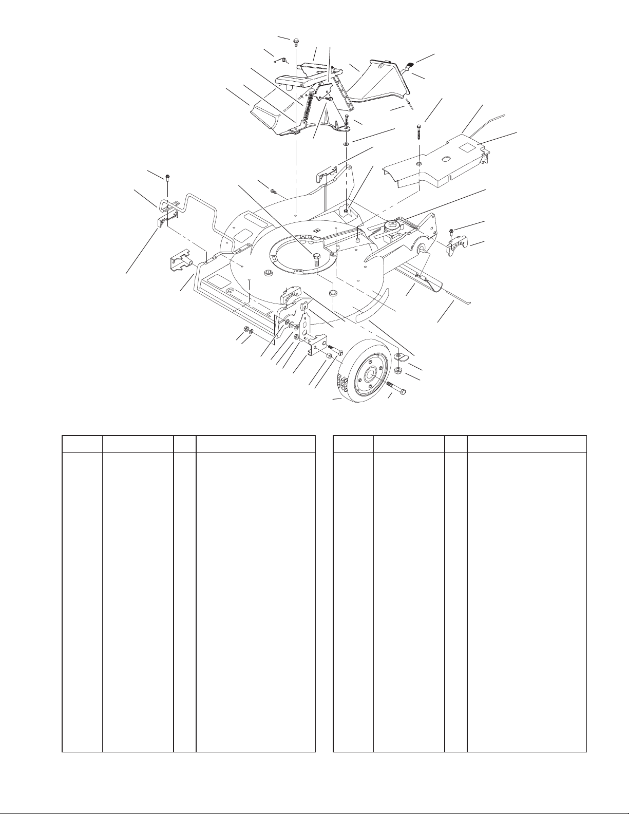
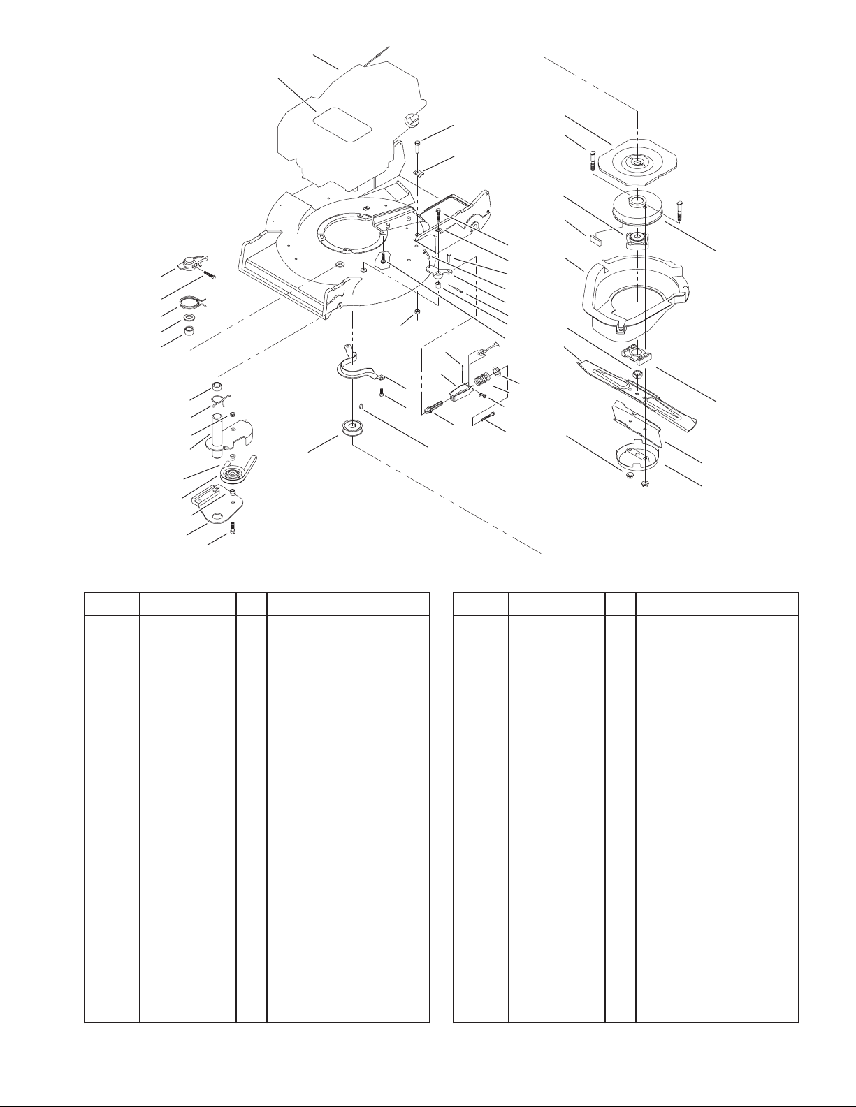
Housing Assembly
DescriptionPart No. Qty.Ref. No. DescriptionPart No. Qty.Ref. No.
1 98–7144 1 Housing
2 3296–6 2 Nut–Lock, NI
3 40–1940 4 Washer
4 32152–2 2 Nut–Conelock
5 66–7560 2 Front Spring Arm ASM
6 257–3 2 Washer–Thrust
7 61–8300 2 Arm–Pivot, Front
8 52–2480 2 Spacer–Wheel
9 27–6232 2 Bolt–Wheel
10 53–7720 2 Wheel & Tire ASM
11 323–12 2 Screw–HH
12 25–7740 2 Knob–Arm
13 49–8760 1 Quadrant–Front, LH
14 46–6811 3 Screw–HWH
17 44–0580 1 Shield–Trailing
18 33–3208 1 Rod–Shield
19 49–8740 1 Quadrant–Rear, LH
20 74–1861 1 Gear Case ASM
21 99–6298 1 Cover–Belt
22 37–7260 2 Screw–HH
23 3296–42 2 Nut–Lock NI
24 49–8750 1 Quadrant–Rear, RH
25 3256–22 2 Washer–Flat
26 321–7 2 Screw–HH
27 77–0502 1 Discharge Plug ASM
27:1 3295–35 1 Rivet–Head, Flat
13
12
5
7
8
9
10
11
18
46
48
49
Sheet No.:2
C–3002
27:3 76–4640 1 Latch–Plug, Discharge
27:4 76–4650 1 Grip–Latch
28 46–8090 2 Screw–Plastite
29 93–3154 1 Latch–Plate
30 93–7351 1 Discharge Door ASM
32 80–3770 1 Retainer–Door
33 76–4660 1 Spring–Door
34 71–9350 1 Bracket–Spring
35 93–6664 1 Decal–Grease, Int’l
36 82–9151 1 Tunnel–Discharge
39 46–6810 1 Screw & Washer ASM
42 49–2040 4 Screw–Tapping
43 49–8770 1 Quadrant–Front, RH
46 92–7988 1 Decal – Recycler
47 323–6 3 Screw–HH
48 84–8930 2 Shield–Retainer
49 3296–39 3 Nut–Lock, NI
52 32144–86 4 Screw–HH
53 99–6722 1 Guard–Engine
3
Page 4
3328–557
4
8
5
3
7
6
11
9
10
2
Sheet No.:A1
C–2988
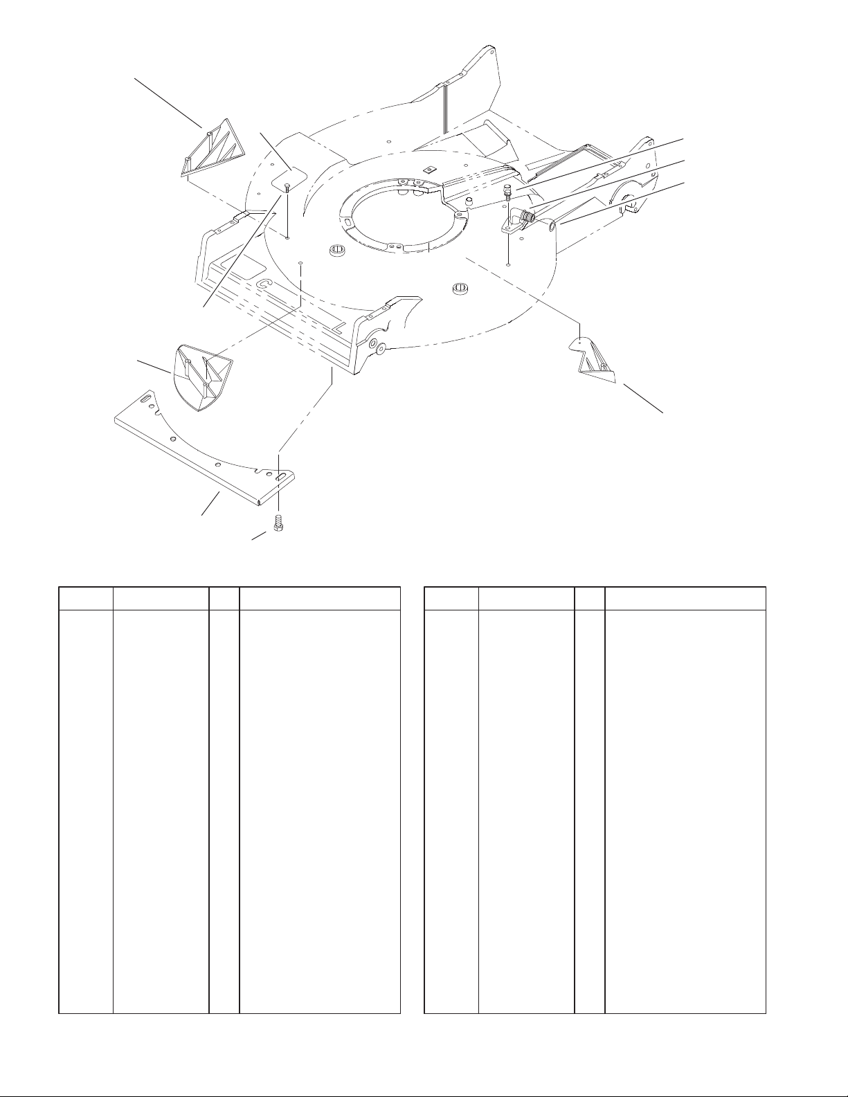
Housing Assembly No. 98–7144
DescriptionPart No. Qty.Ref. No. DescriptionPart No. Qty.Ref. No.
2 92–1750 1 Kicker–Rear
3 92–1720 1 Kicker–Front
4 92–1730 1 Kicker–RH
5 32144–111 6 Screw–PPH
6 32144–70 4 Screw–HH
7 46–5400–03 1 Shield
8 93–6654 1 Decal–Danger Covers
9 95–2747 1 Fitting–Washout
10 46–6290 1 O–Ring
11 46–6811 2 Screw–HWH
4
Page 5
3
2
3328–557
5:1
1
5:2
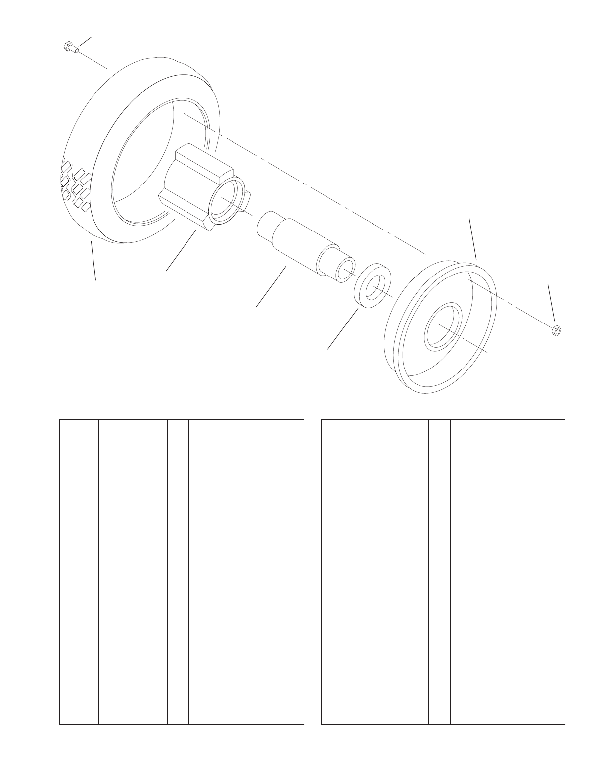
Front Wheel and Tire Assembly
DescriptionPart No. Qty.Ref. No. DescriptionPart No. Qty.Ref. No.
1 53–7740 1 Tire
2 53–7780–06 2 Plate–Wheel, Half
3 321–2 4 Screw–HH
4 3296–42 4 Nut–Lock NI
5 1 Hub & Bearing ASM
5:1 52–2410 1 Hub–Bearing
5:2 52–2440 1 Spacer–Bearing
5:3 52–2450 2 Bearing–Wheel
4
5:3
Sheet No.:A2
C–2989
Not serviced
5
Page 6
3328–557
30
31
39
27
41
42
45
8
24
33
32
31
23
35
479
6
11
5
34
10
17
16
44
24
3
2
18
31
28
25
26
29
22
15
19
29
14
21
12
20
13
37
36
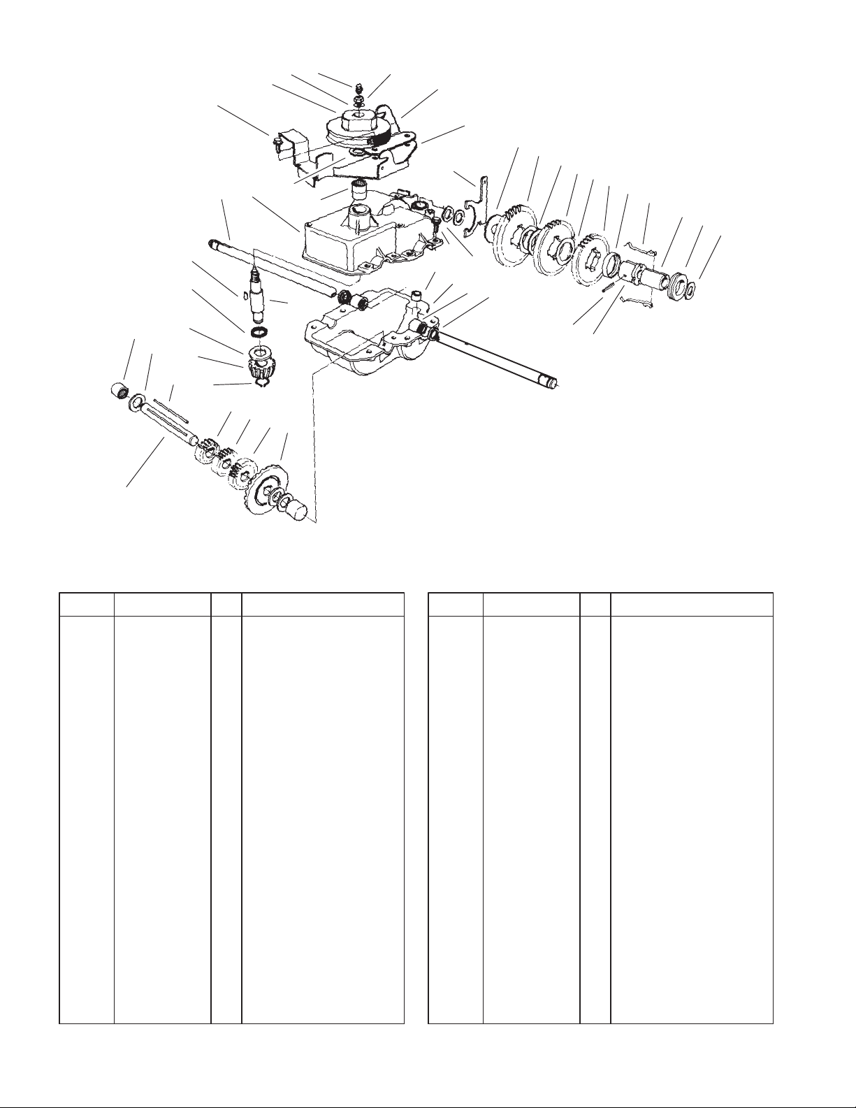
Gear Case Assembly No. 74–1861
DescriptionPart No. Qty.Ref. No. DescriptionPart No. Qty.Ref. No.
2 74–1920 1 Case–Gear, Lower
3 49–8461–03 1 Bracket–Guide, Belt
4 74–1890 1 Shaft–Output
5 32151–57 1 Ring–Retaining
6 47–2910 1 Washer–Thrust
7 68–8190 1 Shaft–Input
8 39–6740 1 Pulley
9 74–1880 1 Case–Gear, Upper
10 3296–5 1 Nut–Lock NI
11 39–6660 1 Pinion–Bevel
12 29–9330 2 Key
13 29–9340 1 Collar–Shift
14 42–4740 1 Gear–38 Tooth
15 29–9271 1 Gear–42 Tooth
16 60–8870 1 Yoke–Shift
17 29–9570 1 Bushing–Yoke
18 47–6730 2 Seal–Oil
19 55–8010 1 Sleeve–Gear
20 39–6720 1 Sleeve
21 55–8020 1 Retainer–Key
22 3285–19 1 Pin–Groove
23 47–7270 2 Bearing
24 49–2040 6 Screw–Tapping
25 29–9690 1 Washer
26 46–3560 1 Gear
27 3257–1 2 Key–Woodruff
Sheet No.:A3
C–2990
28 48–2060 2 Bearing–Roller
29 36–4770 3 Washer
30 252–103 2 Bearing–Closed
31 36–4792 4 Washer–Thrust
32 39–6650 1 Gear–18t
33 46–3550 1 Gear–14t
34 46–3540 1 Gear–12t
35 74–1760 1 Gear–Bevel
36 53–7950 1 Shaft–Intermediate
37 36–4780 3 Washer
39 39–7842 1 Key
41 47–7260 1 Seal
42 302–63 1 Zerk
44 74–1750–03 1 Brake–Engage,
Traction
45 3256–45 1 Washer–Flat
6
Page 7
1
3
3328–557
28
29
30
31
32
36
35
42
32
33
39
34
37
38
10
53
41
50
47
23
44
25
26
43
27
7
24
46
45
11
12
14
13:1
16
18
19
22
13
17
20
21
Sheet No.:3
51
52
43
49
8
48
9
Engine and Blade Brake Clutch Assembly
DescriptionPart No. Qty.Ref. No. DescriptionPart No. Qty.Ref. No.
1 104–1333 1 Engine–Kawasaki
Fc150v
3 104–1335 1 Decal–Engine
7 100–2835 3 Screw–Mount, Engine
8 66–0570–03 1 Bracket–Guide, Belt
9 3257–17 1 Key–Woodruff
10 56–6180 1 Driver–Pulley
11 56–6160–03 1 Flywheel – Bbc
12 42–3190 2 Bolt–Blade
13 94–9431 1 Brake Drum ASM
13:1 52–3480 2 Dampner–Vibration
14 42–6890 1 Hub ASM
16 46–5693 1 Shield
17 62–4280 1 Spacer–Blade
18 603164 1 Nut–Blade
19 91–2256–03 1 Blade
20 91–2255–03 1 Stiffener–Blade
21 80–2770 1 Cup–Anti–Scalp
22 54–9190 2 Nut–Lock
23 32104–107 1 Screw–HH
24 3256–23 1 Washer–Flat
25 49–2810 1 Link – Control
26 49–7960 1 Bellcrank
27 49–7950 1 Sleeve–Bellcrank
28 49–2820 1 Lever
29 32104–96 1 Screw–HH
30 49–7970 1 Spring–Torsion
31 70–1160 1 Washer
32 68–9780 2 Bearing
33 85–6880 1 Spring–Torsion
34 84–9130 1 Plate–Brake
35 42–0884 1 V–Belt
36 46–5650 1 Pulley–Idler
37 46–5631 2 Hub–Pulley, Idler
38 322–6 1 Screw–HH
39 3296–47 1 Nut–Lock, NI
41 32144–70 3 Screw–HH
42 84–9180 1 Brake Plate ASM
43 3272–1 2 Pin–Cotter
44 84–9050 1 Pin–Spring
45 65–5280 1 Retainer–Spring
46 84–9100 1 Spring
47 46–7040 1 Screw–HWHTF
48 84–8870 1 Guide–Spring
49 84–8880–03 1 Bracket–Spring
50 84–9040 1 Pin–Cable
51 322–6 1 Screw–HH
52 62–3720 1 Clamp–Cable
53 3296–58 1 Nut–Lock NI
7
Page 8
3328–557
26
1
21
2
24
13
4
23
22
25
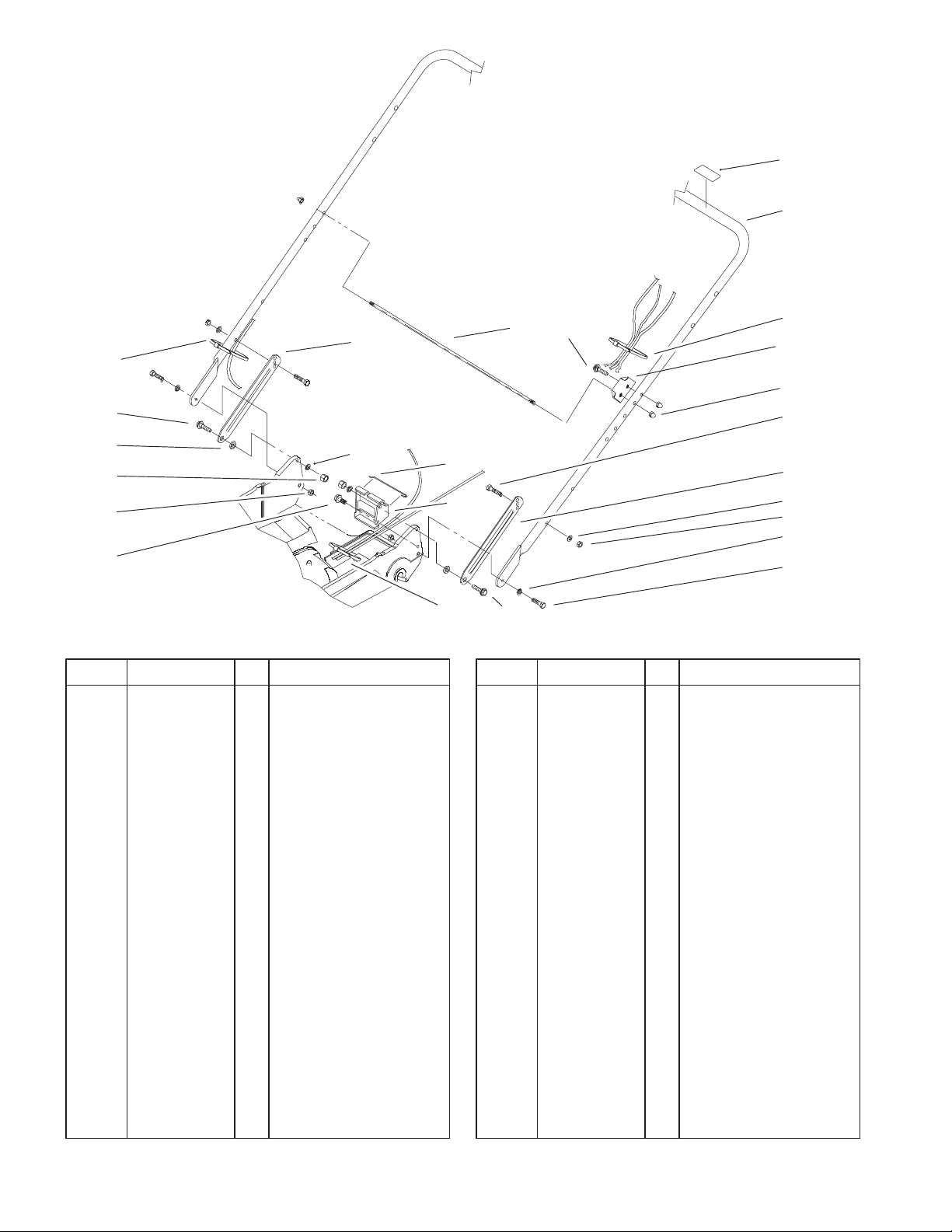
Handle and Handle Latch Assembly
DescriptionPart No. Qty.Ref. No. DescriptionPart No. Qty.Ref. No.
1 98–2385–03 1 Handle
2 3290–378 2 Tie–Cable
3 32111–7 3 Nut–Cap
4 3296–29 4 Nut–Lock
5 3290–456 4 Washer–Belleville
6 100–3298–03 1 Latch–Handle, LH
7 322–7 2 Screw–HH
9 322–6 2 Screw–HH
10 74–1741 1 Bracket–Traction
Adjustment
11 46–7030 1 Retainer–Cable
13 3–3287 2 Spacer–Latch, Handle
14 27–7210 1 Screw–Shoulder
15 48–2810 1 Rod–Support, Bag
21 100–3297–03 1 Latch–Handle, RH
22 32144–70 1 Screw–HH
23 3296–47 2 Nut–Lock, NI
24 27–7211 1 Screw–Shoulder
25 3256–23 2 Washer–Flat
26 98–4387 1 Decal–Protection, Ear
27 104–1326 1 Plate – Bag Aligning
28 3229–3 1 Screw–CARR
28
15
11
10
2
14
2
27
3
7
6
5
4
5
9
Sheet No.:4
8
Page 9
31
3328–557
23
24
22
26
2120
25
1
2
32
33
34
19
18
3
17:4
17:1
17
17:3
4
7
33
13
3
8
9
10
11
7
14
16
15
5
6
12
Sheet No.:5
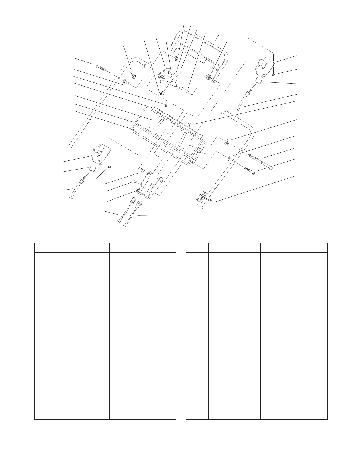
Controls, Bails and Panel Assembly
DescriptionPart No. Qty.Ref. No. DescriptionPart No. Qty.Ref. No.
1 84–8940–03 1 Bar–Control
2 85–6750 1 Spring–Control
3 3250–12 8 Screw–PPH
4 85–6770 1 Control–Throttle
5 84–9120 1 Cable–Traction
6 84–9110 1 Cable–Clutch
7 3296–2 8 Nut–Lock
8 71–9310 1 Spacer
9 71–9320 1 Spacer
10 322–19 1 Screw–HH
11 46–6430 1 Screw–Handle
12 3290–378 2 Tie–Cable
13 100–2839 1 Cable–Throttle
14 3296–29 1 Nut–Lock
15 92–1778–03 1 Bracket–Control
16 3296–42 1 Nut–Lock NI
17 99–8137 1 Panel ASM
17:1 98–2006 1 Decal–Panel, Control
17:3 85–6720 1 Decal–Panel, Proline
17:4 93–6655 1 Decal–Panel, Rear
18 49–1631 1 Spacer–Support
19 17–9427 1 Screw
20 86–9320 1 Bushing–Flange
21 84–9000 1 Lever–Traction
22 3272–1 1 Pin–Cotter
23 3296–58 1 Nut–Lock NI
24 84–8990 1 Lever–Bbc
25 84–9040 1 Pin–Cable
26 84–9030 1 Spacer–Bracket,
Control
*27 85–6780 1 Retainer–Cable,
Throttle
31 32104–76 6 Screw
32 99–2542 1 Control–Shift, Bbc
33 85–6780 1 Retainer–Cable,
Throttle
34 99–2541 1 Cable–Shift, Bbc
* Not illustrated
9
Page 10

3328–557
1
20
19
23
27
13
12
18
17
16
16:5
16:1
16:2
2
3
4
5
16:3
6
7
15
14
11
Gear Case and Rear Wheel Assembly
DescriptionPart No. Qty.Ref. No. DescriptionPart No. Qty.Ref. No.
1 36–8070 1 V–Belt
2 32151–36 2 Ring–Retaining
3 74–1810 2 Washer
4 48–2170 2 Cap–End
5 32152–2 2 Nut–Conelock
6 62–3830 2 Washer–Thrust, Outer
7 39–9160 2 Gear–Pinion
8 74–1640 2 Cover–Wheel
9 74–1720 2 Wheel & Tire ASM
10 323–13 2 Screw–HH
11 74–1650 2 Spacer–Cover, Wheel
12 39–9650 2 Spring–Compression
13 612066 2 Key
14 32151–68 4 Ring–Retaining
15 49–7700 2 Washer–Thrust, Outer
16 74–1851 2 Pivot Arm ASM
16:1 47–6730 1 Seal–Oil
16:2 48–2060 1 Bearing–Roller
16:3 52–2450 1 Bearing–Wheel
16:5 92–6316 1 Zerk–Drive, Special
17 66–7561 2 Rear Spring Arm ASM
18 25–7740 2 Knob–Arm
19 29–9560 1 Lever–Shift
20 32121–99 1 Pin–Coil
23 32144–70 1 Screw–HH
8
9
10
Sheet No.:6
27 62–3720 1 Clamp–Cable
*99 99–2535 1 Grass Bag ASM
* Not illustrated
10
Page 11

3328–557
3
1
6:1
5
2
6:2
4
Rear Wheel and Tire Assembly No. 74–1720
DescriptionPart No. Qty.Ref. No. DescriptionPart No. Qty.Ref. No.
1 53–7740 1 Tire
2 53–7780–06 1 Plate–Wheel, Half
3 321–2 4 Screw–HH
4 3296–42 4 Nut–Lock NI
5 92–4957–06 1 Wheel Half/Gear ASM
6 1 Hub & Bearing ASM
6:1 52–2410 1 Hub–Bearing
6:2 52–2440 1 Spacer–Bearing
6:3 52–2450 2 Bearing–Wheel
6:3
Sheet No.:A4
C–2991
Not serviced
11
Page 12

3328–557
7
6
2
4
1
3
Grass Bag Assembly No. 99–2535
DescriptionPart No. Qty.Ref. No. DescriptionPart No. Qty.Ref. No.
1 1 Grass Bag ASM
1 33–4820 1 Hinge–Door, Bag
2 42–4030 1 Frame–Bag, Upper
3 3290–422 2 Nut–Push
4 36–6910 2 Spring
5 42–4020 1 Frame–Bag
6 98–9225 1 Bag–Grass
7 48–2840 1 Door–Bag, Grass
5
Sheet No.:A5
C–2992
12
Page 13

28
3328–557
21
9
5
8
28
10
7
1
29
26
11
20
3
4
27
17
12
32
33
Cylinder/Crankcase Assembly
DescriptionPart No. Qty.Ref. No. DescriptionPart No. Qty.Ref. No.
1 100–2742 1 Gasket–Head
2 100–2743 1 Head–Cylinder,
Complete
3 100–2744 1 Gasket–Case, Rocker
4 100–2745 1 Case–Rocker
5 100–2746 1 Cover–Gasket
6 100–2747 1 Gasket–Cover,
Crankcase
7 100–2748 1 Plate
8 100–2749 1 Plate
9 100–2779 1 Cover
10 100–2780 1 Valve
11 100–2781 1 Valve
12 100–2782 1 Cover–Crankcase
13 100–2840 1 O–Ring
14 100–2841 1 Bearing–Ball
15 93–8516 2 Pin
16 100–2842 1 Bolt
17 KW10035 4 Bolt–Flanged
18 KW10033 1 Bolt–Flanged
19 100–2610 6 Bolt–Flanged
20 100–2804 4 Bolt–Flanged
21 100–2609 4 Bolt–Flanged
22 100–2843 1 Washer
23 100–2844 1 Washer
24 100–2854 1 Plug
6
25
31
22
2
26
30
19
33
15
14
16
23
13
24
Sheet No.:3
25 100–2846 1 Tube
26 100–2847 2 Seal–Oil
27 100–2848 2 Pin
28 93–8549 2 Screw
29 100–2849 1 Crankcase–Complete
30 99–6728 1 Slinger–Oil
31 99–6729 1 Shaft
32 99–6730 1 Gasket
33 100–2855 1 Bolt–Flanged
13
Page 14

3328–557
2
9
3
11
11
12
12
6
4
15
9
3
13
15
14
4
5
7
5
7
10
1
13
8
13
Sheet No.:4
Valves/Camshaft Assembly
DescriptionPart No. Qty.Ref. No. DescriptionPart No. Qty.Ref. No.
1 100–2727 1 Valve–Intake
2 100–2728 1 Valve–Exhaust
3 100–2729 2 Retainer–Spring, Valve
4 100–2730 2 Arm–Rocker
5 100–2731 2 Tappet
6 100–2732 1 Guide
7 100–2733 2 Rod–Push
8 100–2734 1 Decompressor
9 100–2735 2 Spring–Valve, Engine
10 100–2736 1 Camshaft–Complete
11 93–8533 2 Nut
12 93–8534 2 Nut
13 100–2739 3 Pin
14 100–2740 1 Spring
15 100–2741 2 Bolt
14
Page 15

6
3328–557
14
23
9
27
10
4
15
3
18
20
1
16
19
16
2
21
26
19
5
13
7
8
11
17
22
Control Linkage Assembly
DescriptionPart No. Qty.Ref. No. DescriptionPart No. Qty.Ref. No.
1 100–2700 1 Lever
2 100–2701 1 Lever
3 100–2702 1 Link–Choke
4 100–2703 1 Link
5 100–2704 1 Arm ASM
6 100–2705 1 Arm–Pivot
7 100–2706 1 Spring–Governor
8 100–2707 1 Control Panel ASM
9 100–2708 1 Sleeve
10 93–8611 1 Governor ASM
11 100–2710 1 Panel–Control
*12 93–8608 1 Washer
13 93–8631 1 Nut
14 93–8595 1 Nut
15 94–6842 1 Washer
16 100–2715 2 Washer
17 95–9849 1 Clamp
18 100–2717 1 Link–Spring
19 100–2718 2 Collar
20 93–8588 1 Spring
21 100–2720 1 Spring
22 95–9853 1 Bolt
23 93–8608 1 Washer
24 95–9837 1 Bolt – Flanged
25 100–2724 2 Bolt
24
Sheet No.:5
25
26 100–2725 1 Screw–Pan
27 93–8607 1 Pin–Snap
* Not illustrated
15
Page 16

3328–557
2
8
4
7
5
1
10
3
9
Brake Band Assembly
DescriptionPart No. Qty.Ref. No. DescriptionPart No. Qty.Ref. No.
1 100–2783 1 Bracket
2 100–2784 1 Band–Brake
3 100–2785 1 Lever–Brake
4 100–2786 1 Pin
5 100–2787 1 Spring
6 100–2609 1 Bolt–Flanged
7 KW10029 1 Bolt, Flanged
8 100–2671 1 Washer Plain S
9 100–2791 1 Circlip–Type–E
10 100–2792 2 Pin Cotter
6
Sheet No.:6
16
Page 17

3328–557
12
5
13
13
15
10
15
6
18
14
17
11
16
3
4
7
1
2
9
8
Fuel Tank and Valve Assembly
DescriptionPart No. Qty.Ref. No. DescriptionPart No. Qty.Ref. No.
1 100–2808 1 Gasket
2 100–2809 1 Guide
3 100–2810 1 Lever
4 100–2811 1 Filter–Complete
5 100–2812 1 Filter–Fuel
6 100–2814 1 Valve – Fuel
7 100–2813 1 Element–Breather
8 100–2815 1 Tank–Fuel, Complete
9 100–2816 1 Tank Cap ASM
10 100–2817 1 Screw
11 100–2818 1 Clamp
12 100–2819 1 Tube
13 100–2820 2 Clamp
14 100–2821 1 Clamp
15 100–2822 2 Clamp
16 100–2823 1 Tube
17 100–2804 2 Bolt–Flanged
18 100–2825 2 Screw–Pan
17
Sheet No.:7
17
Page 18

3328–557
21
16
13
18
11
12
8
14
7
4
3
15
6
Flywheel/Ignition Assembly
9
20
22
5
1
10
2
17
Sheet No.:8
19
DescriptionPart No. Qty.Ref. No. DescriptionPart No. Qty.Ref. No.
1 100–2650 1 Plate
2 100–2651 1 Cover
3 100–2652 1 Cover
4 100–2653 1 Insulator
5 100–2654 1 Insulator
6 KW10087 1 Plug–Cap
7 100–2656 1 Terminal
8 100–2657 1 Ignition Coil ASM
9 100–2658 1 Flywheel–Complete
10 100–2659 1 Wire Lead
11 100–2660 1 Wire–Lead
12 93–8571 1 Key
13 KW10676 1 Plug–Spark
14 100–2663 1 Bolt
15 100–2664 1 Clamp
16 100–2665 1 Washer
17 100–2666 1 Bolt Upset
18 100–2610 2 Bolt–Flanged
19 100–2668 1 Nut–Hex
20 100–2669 1 Nut Hex
21 93–8568 1 Nut
22 100–2671 1 Washer Plain S
18
Page 19

3328–557
15
6
28
3
13
4
5
11
31
29
18
8
16
10
23
9
12
22
27
21
30
20
19
14
33
28
34
24
2
7
Carburetor Assembly
DescriptionPart No. Qty.Ref. No. DescriptionPart No. Qty.Ref. No.
1 100–2611 1 Gasket
2 100–2612 1 Gasket
3 100–2613 1 Gasket–Carburetor
4 100–2614 1 Gasket–Insulator
5 100–2615 1 Carburetor ASM
6 100–2616 1 Screw–Pilot, Air
7 100–2617 1 Float–Chamber
8 100–2618 1 Valve–Throttle
9 100–2619 1 Valve–Float
10 100–2620 1 Float
11 100–2621 1 Shaft–Throttle,
Carburetor
12 100–2622 1 Shaft–Choke,
Carburetor
13 100–2623 1 Insulator
14 100–2624 1 Valve
15 100–2625 1 Limiter
16 100–2626 1 Nozzle–Main
17 100–2627 1 Screw
18 100–2628 1 Screw
19 100–2629 2 Screw
20 100–2630 1 Collar
21 100–2631 1 Collar
22 KW10297 1 Clip
23 100–2633 1 Pin
24 100–2634 1 Jet–Main
32
1
28
17
Sheet No.:9
27 100–2635 1 Jet–Pilot
28 100–2636 3 Spring
29 100–2637 1 Seal
30 100–2638 1 Seal
31 100–2639 1 Collar
32 100–2640 1 Bolt
33 100–2641 1 Tube
34 100–2642 1 Screw–Pan
19
Page 20

3328–557
14
9
10
13
8
12
1
6
7
11
3
4
5
Piston/Crankshaft Assembly
DescriptionPart No. Qty.Ref. No. DescriptionPart No. Qty.Ref. No.
1 100–2672 1 Piston–Engine
2 100–2673 1 Pin–Piston
3 100–2674 1 Set–Ring, Piston
4 100–2675 1 Set–Ring,
Piston–L0.25
5 100–2676 1 Set–Ring,
Piston–L0.50
6 100–2677 1 Piston–Engine, L0.25
7 100–2678 1 Piston–Engine, L0.50
8 100–2828 1 Crankshaft
9 100–2680 1 Connecting Rod ASM
10 100–2681 1 Connecting Rod ASM
(U/S=0.50)
11 100–2682 1 Gear–Helical
12 100–2683 2 Ring–Snap
13 93–8526 1 Key
14 93–8527 2 Bolt–Rod
2
12
Sheet No.:10
20
Page 21

3328–557
16
20
1
3
4
2
13
19
10
11
12
6
18
15
17
22
14
8
9
23
24
Air Filter/Muffler Assemby
DescriptionPart No. Qty.Ref. No. DescriptionPart No. Qty.Ref. No.
1 100–2691 1 Cap–Filter, Air
2 100–2692 1 Element–Filter, Air
3 100–2693 1 Element–Filter, Air
4 100–2694 1 Air Filter Element ASM
5 100–2695 1 Bracket
6 100–2696 1 Gasket–Pipe, Intake
7 100–2697 1 Gasket–Muffler
8 100–2698 1 Pipe–Intake
9 100–2699 1 Muffler–Complete
10 100–2750 1 Cover–Muffler
11 93–8549 3 Screw
12 95–9716 2 Screw
13 93–8631 2 Nut
14 100–2754 2 Spacer
15 100–2755 1 Tube
16 100–2756 1 Bolt
17 100–2757 1 Clamp
18 100–2758 1 Clamp
19 100–2759 2 Washer
20 100–2760 1 Washer
21 100–2761 2 Bolt–Stud
22 100–2762 2 Bolt
23 100–2763 2 Screw–Pan
24 93–8639 2 Washer
7
5
21
Sheet No.:11
21
Page 22

3328–557
6
11
1
9
6
11
7
9
12
Cover/Cooling Assembly
DescriptionPart No. Qty.Ref. No. DescriptionPart No. Qty.Ref. No.
1 100–2600 1 Cover–Upper
2 100–2793 1 Cover–Lower
3 100–2794 1 Cover
4 100–2601 3 Stud
5 100–2602 1 Stud
6 100–2603 4 Nut
7 100–2604 4 Nut
8 100–2606 4 Spacer
9 100–2605 4 Spacer
10 100–2607 1 Grommet
11 100–2760 4 Washer
12 100–2609 2 Bolt–Flanged
13 100–2610 4 Bolt–Flanged
2
5
10
3
4
8
13
Sheet No.:12
22
Page 23

16
3328–557
10
4
9
19
14
15
13
6
16
21
20
5
7
2
8
11
1
3
12
17
18
Sheet No.:13
Dipstick/Oil Filter Assembly
DescriptionPart No. Qty.Ref. No. DescriptionPart No. Qty.Ref. No.
1 KW10010 1 Gasket
2 100–2644 1 Gasket
3 100–2687 1 Guide
4 100–2645 1 Plate
5 100–2643 1 Pump ASM Oil
6 100–2646 1 Cover Pump
7 100–2647 1 Rotor Pump
8 100–2648 1 Pipe Complete
9 100–2649 1 Filter – Screen
10 100–2688 1 Gauge
11 95–9715 1 Joint
12 100–2689 1 Filler
13 100–2801 1 Ring O
14 100–2802 1 Spring
15 100–2803 1 Spring
16 100–2804 6 Bolt–Flanged
17 100–2805 2 Bolt–Flanged
18 100–2806 1 Bolt–Flanged
19 100–2807 1 Ball–Steel
20 100–2690 1 O–Ring
21 KW10761 1 Filter–Oil
23
Page 24

3328–557
5
1
2
12
9
8
14
3
7
13
4
11
Recoil Starter Assembly
DescriptionPart No. Qty.Ref. No. DescriptionPart No. Qty.Ref. No.
1 94–9044 1 Cap – Grip
2 100–2766 1 Holder
3 100–2767 1 Pawl–Starter, Recoil
4 100–2768 1 Retainer–Spring
5 100–2769 1 Grip–Starter, Recoil
6 100–2770 1 Pulley–Starting
7 100–2771 1 Starter–Recoil
8 100–2772 1 Reel–Starter, Recoil
9 100–2836 1 Rope Recoil 3.8x2610
10 100–2774 1 Screw
11 100–2775 1 Washer
12 100–2776 1 Spring–Recoil
13 100–2777 1 Spring
14 93–8555 1 Spring–Return
10
6
Sheet No.:14
24
Page 25

Date
Maintenance Record
25
Page 26

Date
Maintenance Record
26
Page 27

Date
Maintenance Record
27
Page 28

 Loading...