


Commercial Trim Mowers
Various Models
Form No. 3360-643 Rev A
Addendum
Important: The instructions in this
Addendum
replace procedure 1 in Setup in your
Operator’s Manual
therefore, use these instructions when you set up your mower.
Note: In your Parts Catalog, replace the 2 hex-head screws (322-7) in the handle assembly with the 2 handle screws
(92-4095). Also, replace the 2 self-tapping hex head screws (701243) with the 2 self-tapping hex head screws
(32144-49). The spacer (5-0652) is not listed in your Parts Catalog. Therefore, keep this Addendum with your Parts
Catalog.
1
Installing the Handle
Parts needed for this procedure:
Oval-head bolt (models 22164, 22164TE, and 22194
6
only)
6
Locknut (models 22164, 22164TE, and 22194 only)
Upper handle (models 22164, 22164TE, and 22194
1
only)
2
Oval-head bolt (models 22163 and 22193 only)
2
Locknut (models 22163 and 22193 only)
2
Self-tapping hex head screw (32144-49; all models)
2
Washer (all models)
2
Spacer (5-0652; all models)
1
Cable tie (all models)
;
Procedure
1. Attach the upper handle to the lower handle using
4 oval-head bolts and 4 locknuts (Models 22164,
22164TE, and 22194 only).
Note: Ensure that the bolt heads are to the outside
of the handle.
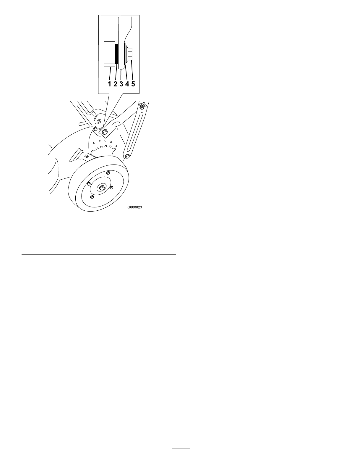
2. Attach the handle to the mower housing with
2 self-tapping hex head screws, 2 washers, and
2 spacers (Figure 1), but do not tighten the
self-tapping hex head screws.
Note: Ensure that you insert the spacers between
the mower housing and the handle (Figure 2).
© 2008—The Toro® Company
8111 Lyndale Avenue South
Bloomington, MN 55420
Register at www.Toro.com.
Figure 1
1. End cap on rear door rod
2. Self-tapping hex head
screw, washer, and spacer
(2)
3. Locknut (2)
4. Handle brace (2)
5. Bolt head aligned with the
handle
Original Instructions (EN)
Printed in the USA.
All Rights Reserved
so that the bolt heads are tight against the handle,
and then tighten the locknuts (Figure 1).
6. Tighten the rest of the fasteners on the handle and
handle braces.
7. Use the cable tie provided to secure the control
cable(s) to the handle.
Note: Attach the cable tie as low as possible on the
handle to prevent the cable(s) from hooking onto
the end cap on the rear door rod and interfering with
the self-propel system (Figure 1).
Figure 2
1. Mower housing 4. Washer
2. Spacer 5. Self-tapping hex head
3. Handle
screw
3. Move the handle to the operating position.
4. Attach the handle braces to the lower handle sides
with 2 oval-head bolts and secure them nger tight
using 2 locknuts (Figure 1).
Important: Ensure that the bolt heads are to
the
inside
of the handle.
5. Align the oval bolt heads with the handle as shown
in Figure 1; then secure the handle as follows:
• If the holes in the handle are round, align the
oval bolt heads with the handle as shown in
Figure 1; then, holding the heads in that position,
tighten each nut with a wrench to pull the square
shank into the handle until the bolt heads are
tight against the handle.
Note: The square shank of the bolts will not
readily t into the round holes.
• If the holes in the handle are square, align the
oval head bolt heads with the handle as shown in
Figure 1, insert the square shank into the handle
2
 Loading...