

Page 1

FORM NO. 3322–361
ProLine
21” Recycler
Walk-behind Power Mower
Model No. 22162 — 9900001 & Up
II
Operator’s Manual
Para
obtener una versión gratis de este manual en español, escriba a la dirección
indicada más abajo. Asegúrese de indicar el modelo y el número de serie de su producto.
The T
oro Company
, Attn: Parts Dept., 8111 L
yndale A
ve S, Bloomington, MN 55420–1
196
English (EN)
Page 2
Contents
Page
Introduction 2.
Safety 3
Safe Operating Practices3. . . . . . . . . . . . . . . . . . . .
General Operation3. . . . . . . . . . . . . . . . . . . . . . . . .
While Operating3. . . . . . . . . . . . . . . . . . . . . . . . . . .
Maintenance And Storage4. . . . . . . . . . . . . . . . . . .
Safety and Instruction Decals4. . . . . . . . . . . . . . . . .
Assembly 5
Handle 5
Gas T
Dischar
Before Starting7. . . . . . . . . . . . . . . . . . . . . . . . . . . . . . .
Fill Crankcase W
Fill Fuel T
Recycling T
General T
Operation 9
Operating T
Controls 9
Starting, Stopping, and Self-propelling10. . . . . . . . .
Using Dischar
Using Grass Bag11. . . . . . . . . . . . . . . . . . . . . . . . . . .
Adjusting Height-of-cut12. . . . . . . . . . . . . . . . . . . . .
Maintenance 12
Servicing Air Cleaner13. . . . . . . . . . . . . . . . . . . . . . .
Replacing Spark Plug13. . . . . . . . . . . . . . . . . . . . . . .
Draining Gasoline13. . . . . . . . . . . . . . . . . . . . . . . . .
Changing Crankcase Oil14. . . . . . . . . . . . . . . . . . . .
Replacing Oil Filter14. . . . . . . . . . . . . . . . . . . . . . . .
Adjusting Throttle14. . . . . . . . . . . . . . . . . . . . . . . . .
Cleaning Cooling System15. . . . . . . . . . . . . . . . . . . .
Adjusting Wheel Drive15. . . . . . . . . . . . . . . . . . . . .
Inspecting/Removing/Sharpening Blade15. . . . . . . .
Lubrication 16
Lubricating Gear Case17. . . . . . . . . . . . . . . . . . . . . .
Adjusting Blade Brake Cable17. . . . . . . . . . . . . . . . .
Cleaning Mower17. . . . . . . . . . . . . . . . . . . . . . . . . . .
Cleaning Blade Brake Clutch Shield19. . . . . . . . . . .
Servicing Wheels (Fig. 33)19. . . . . . . . . . . . . . . . . .
Fuel Filter20. . . . . . . . . . . . . . . . . . . . . . . . . . . . . . . .
Storage 20
Accessories 21
Federal and California Emission Control
W
arranty Statement22. . . . . . . . . . . . . . . . . . . . . . . . . .
Warranty 24
. . . . . . . . . . . . . . . . . . . . . . . . . . . . . . . .
. . . . . . . . . . . . . . . . . . . . . . . . . . . . . . . . . . . . . .
. . . . . . . . . . . . . . . . . . . . . . . . . . . . . . . . . . .
. . . . . . . . . . . . . . . . . . . . . . . . . . . . . . . . . .
ank 5
. . . . . . . . . . . . . . . . . . . . . . . . . . . . . . . . .
ge T
unnel Plug6. . . . . . . . . . . . . . . . . . . . . .
ith Oil7. . . . . . . . . . . . . . . . . . . . .
ank With Gasoline7. . . . . . . . . . . . . . . . .
ips 8
. . . . . . . . . . . . . . . . . . . . . . . . . . . . . . .
ips 8
. . . . . . . . . . . . . . . . . . . . . . . . . . . . . .
. . . . . . . . . . . . . . . . . . . . . . . . . . . . . . . . . . .
ips 9
. . . . . . . . . . . . . . . . . . . . . . . . . . . .
. . . . . . . . . . . . . . . . . . . . . . . . . . . . . . . . .
ge T
unnel Plug10. . . . . . . . . . . . . . . .
. . . . . . . . . . . . . . . . . . . . . . . . . . . . . . . . .
. . . . . . . . . . . . . . . . . . . . . . . . . . . . . . .
. . . . . . . . . . . . . . . . . . . . . . . . . . . . . . . . . . . . .
. . . . . . . . . . . . . . . . . . . . . . . . . . . . . . . . .
. . . . . . . . . . . . . . . . . . . . . . . . . . . . . . . . . . . .
WARNING
The engine exhaust fr
chemicals known to the State of California to
cause cancer
harm.
, birth defects, or other r
om this pr
oduct contains
eproductive
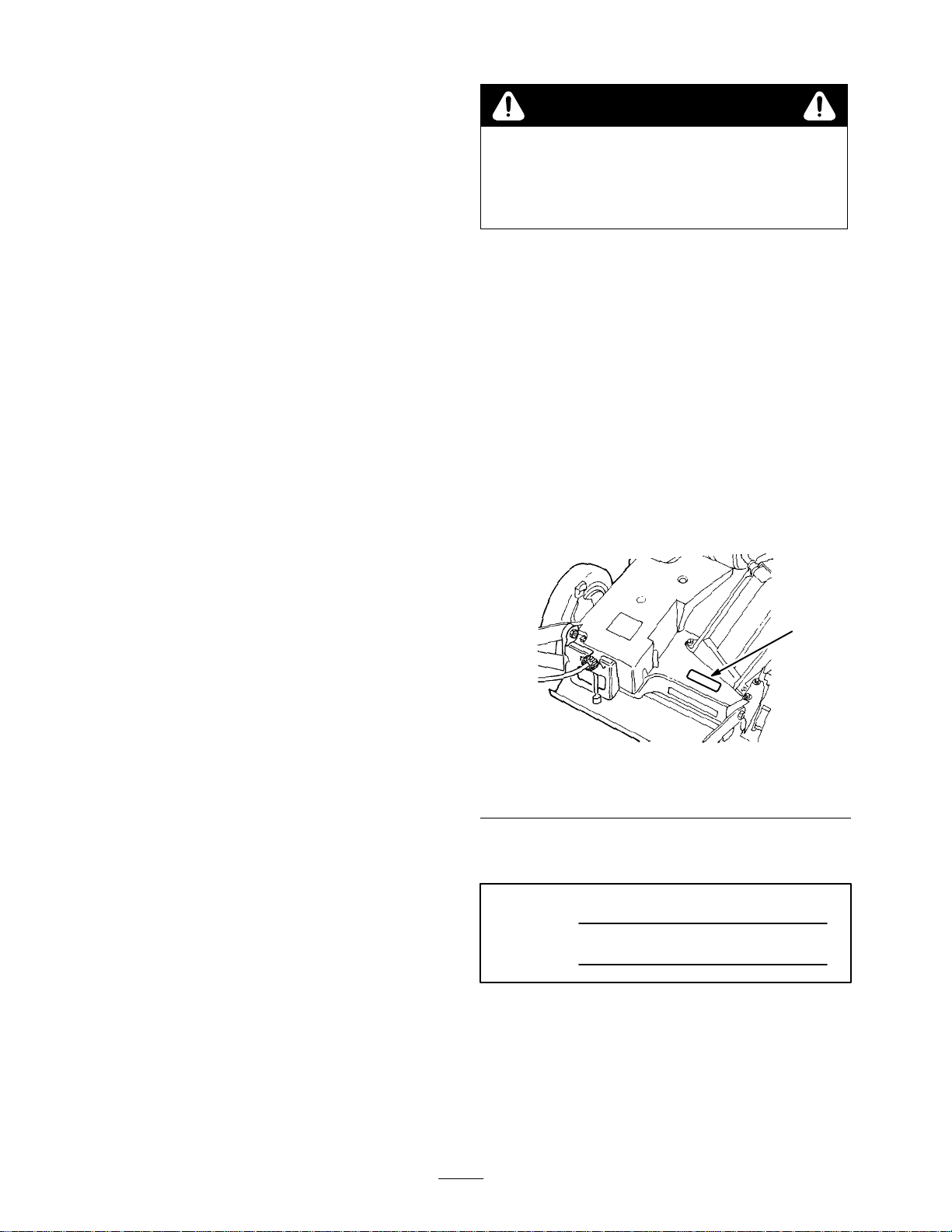
Introduction
Thank you for purchasing a T
All of us at T
your new product, so feel free to contact your local
Authorized Service Dealer for help with service, genuine
T
oro parts, or other information you may require.
Whenever you contact your Authorized Service Dealer or
the factory
your product. These numbers will help the Service Dealer
or Service Representative provide exact information about
your specific product. Y
number decal located in a unique place on the product
(Fig. 1).
1. Model
For
your convenience, write the product model and serial
numbers in the space below
Model No:
Serial No.
Read
this manual carefully to learn how to operate and
maintain your product correctly
help you and others avoid personal injury and damage to
the product. Although T
safe, state-of-the-art products, you are responsible for
using the product properly and safely
responsible for training persons who you allow to use the
product about safe operation.
oro want you to be completely satisfied with
, always know the model and serial numbers of
and serial number decal
oro product.
ou will find the model and serial
1
Figure
oro designs, produces and markets
1
.
. Reading this manual will
. Y
ou are also
224
EThe Toro Company – 1998
All Rights Reserved
2
Printed in USA
Page 3

The T
oro warning system in this manual identifies
potential hazards and has special safety messages that help
you and others avoid personal injury
DANGER, W
used to identify the level of hazard. However
of the hazard, be extremely careful.
DANGER
serious injury or death if the recommended precautions
are not followed.
WARNING
or death if the recommended precautions are not followed.
CAUTION
moderate injury if the recommended precautions are not
followed.
wo other words are also used to highlight information.
T
“Important” calls attention to special mechanical
information and “Note” emphasizes general information
worthy of special attention.
The left and right side of the machine is determined by
standing behind the handle in the normal operator
position.
ARNING and CAUTION are signal words
signals an extreme hazard that will cause
signals a hazard that may cause serious injury
signals a hazard that may cause minor or
, even death.
, regardless
’s
General
1. Read
mower
use of the mower
mower or adults to operate it without proper
instructions.
Keep everyone, especially children and pets, away
2.
from area of operation. Thoroughly inspect area where
mower will be used and remove sticks, stones, wire,
and debris.
3. W
ear long pants and substantial shoes. Do not operate
mower while wearing open-toed shoes, loose clothing,
jewelry or when barefoot.
4.
Always wear safety glasses or eye shields during
operation to protect eyes from foreign objects that may
be thrown from the machine. W
protection, protective gloves and a safety helmet is
advisable and may be required by local regulations.
5.
Check fuel level before starting engine. Do not fill fuel
tank indoors, when the engine is running, or until
engine cools for several minutes after running. W
up spilled gasoline before starting engine.
Operation
this manual carefully before operating the
. Become familiar with the controls and proper
. Never allow children to operate the
earing of hearing
ipe
Safety
This mower meets or exceeds CPSC blade safety
requir
ements for walk behind r
B71.4–1990 specifications of the American National
Standards Institute. However
maintenance by the operator or owner can r
injury
. T
o r
educe the potential for injury, comply with
these safety instructions and always pay attention to
the safety alert symbol
W
ARNING and DANGER. Failur
these instructions may r
Safe
This
throwing objects. Always follow all safety instructions to
avoid serious injury or death.
This mower is designed for cutting and recutting grass or
when equipped with a grass bag, for catching cut grass.
Any use for purposes other than these could prove
dangerous to user or bystanders.
Operating Practices
product is capable of amputating hands and feet and
esult in personal injury
otary mowers and the
, impr
oper use or
esult in
which means CAUTION,
e to comply with
.
6.
Keep all guards, shields, and safety devices in place.
Repair or replace damaged or missing parts, including
decals. Check all safety devices before each use.
7.
Blade and traction drive are designed to stop when the
control bar is released. Ensure control bar functions
properly before and during each use of mower
While
1. Do
2.
3.
,
4.
5.
Operating
not run engine indoors.
Always maintain secure footing. Keep a firm grip on
the handle and walk; never run. Never operate mower
in wet grass. Mow only in daylight or in good artificial
light.
Mow across the face of slopes; never up and down.
Use extreme caution when changing direction on
slopes. Do not mow excessively steep slopes.
Keep face, hands, and feet away from the mower
housing and cutter blade when the engine is running.
Stay behind the handle until the engine stops and keep
clear of dischar
When bagging grass, stop engine and ensure dischar
door is closed before removing and emptying bag.
ge opening at all times.
.
ge
3
Page 4
6.
Stop the engine and wait for all moving parts to stop
before unclogging dischar
bag or dischar
hand, to unclog dischar
unclog the tunnel with the engine running.
7.
Since the blade rotates for a few seconds after
releasing the blade control bar
until all moving parts stop.
8.
After striking a foreign object or if mower vibrates
abnormally
plug. Check mower for damage and make all repairs
before using mower again.
9.
Stop the engine and wait for all moving parts to stop
before adjusting the height-of-cut.
10.
Stop the blade when crossing a gravel driveway
or sidewalk.
11.
Stop engine before leaving the operator
position—behind the handle. Disconnect wire from
spark plug if mower will be unattended or not used.
12.
Do not touch engine while it is running or shortly after
it is stopped because engine will be hot enough to
cause a burn.
13.
Refuel only when engine is cool.
ge tunnel plug. Use a stick, not your
, stop engine and remove wire from spark
Maintenance
ge tunnel, removing grass
ge tunnel. Never attempt to
, stay behind the handle
’s
And Storage
, road
2.
Before mower is cleaned, inspected, serviced, or
adjusted, stop engine and disconnect wire from spark
plug. Keep wire away from plug to prevent accidental
starting.
o ensure the mower is in safe operating condition,
3. T
frequently check and keep all nuts, bolts, and screws
tight. Ensure blade nuts are tightened to 15–27 ft–lb
(20–37 N
o reduce fire hazard, keep engine free of excessive
4. T
grease, grass, leaves, and accumulation of dirt.
5.
Check grass catcher bag frequently for wear or
deterioration. Replace with a new bag for your
protection. Check that replacement bags comply with
original T
6.
Allow engine to cool before storing mower in any
enclosure. Do not store mower near any open flame or
where gasoline fumes may be ignited by a spark.
7.
Do not overspeed the engine by changing governor
settings.
At the time of manufacture, the mower conformed to
8.
the safety standards in ef
assure best performance and continued safety
certification of the mower
replacement parts and accessories. Replacement parts
and accessories made by other manufacturers may
result in non-conformance with the safety standards,
and that could be dangerous.
m).
ORO recommendations or specifications.
fect for rotary mowers. T
, use genuine T
ORO
o
1. Perform
in this manual. If major repairs are ever needed or if
assistance is desired, contact your local Authorized
T
Safety
only those maintenance instructions described
ORO Service Dealer
.
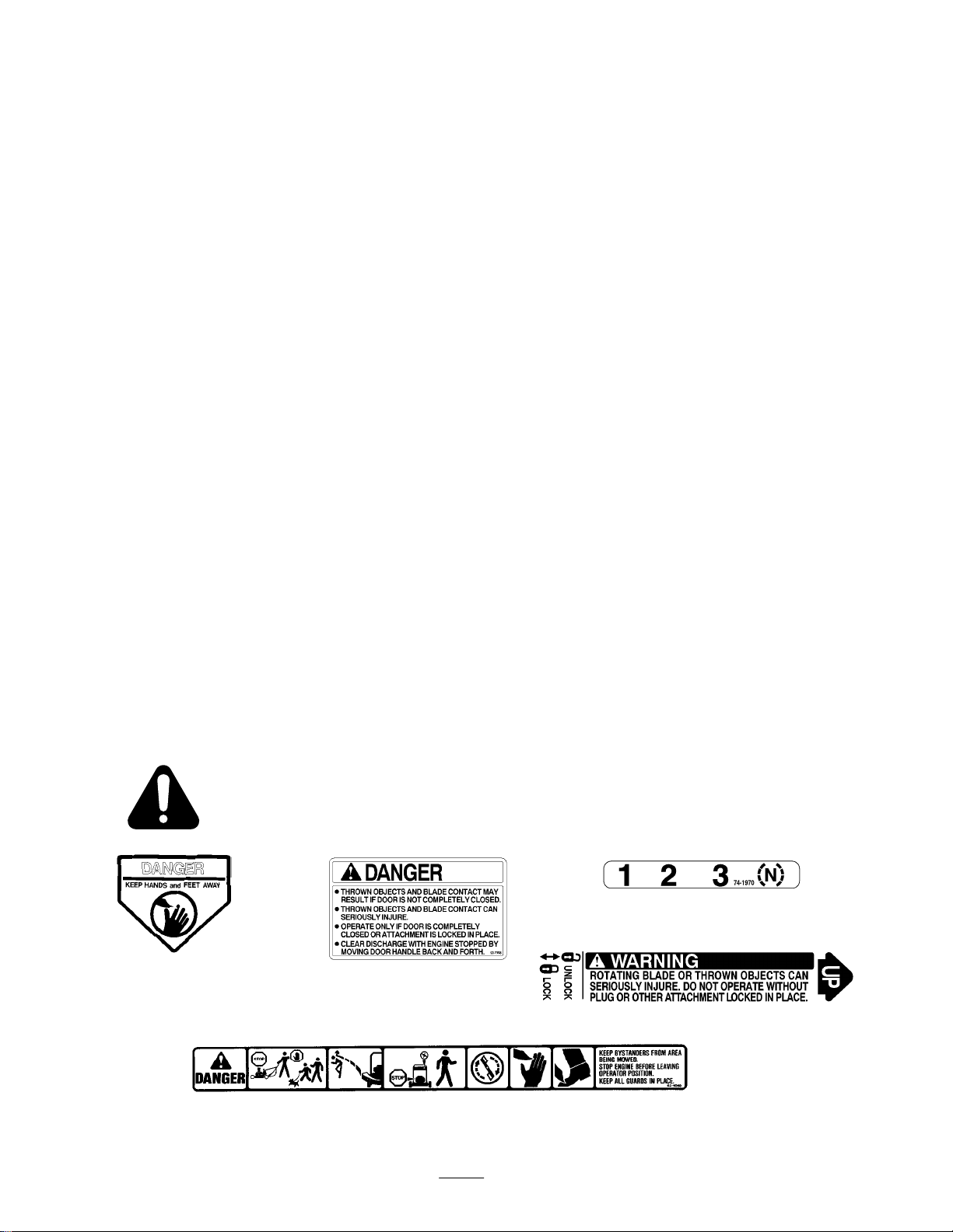
and Instruction Decals
Safety
decals and instructions are easily visible to the operator and are located near any
area of potential danger
"$% #
ON
. Replace any decal that is damaged or lost.
DISCHARGE TUNNEL
!
"$% #
"$% #
4
Page 5
Assembly
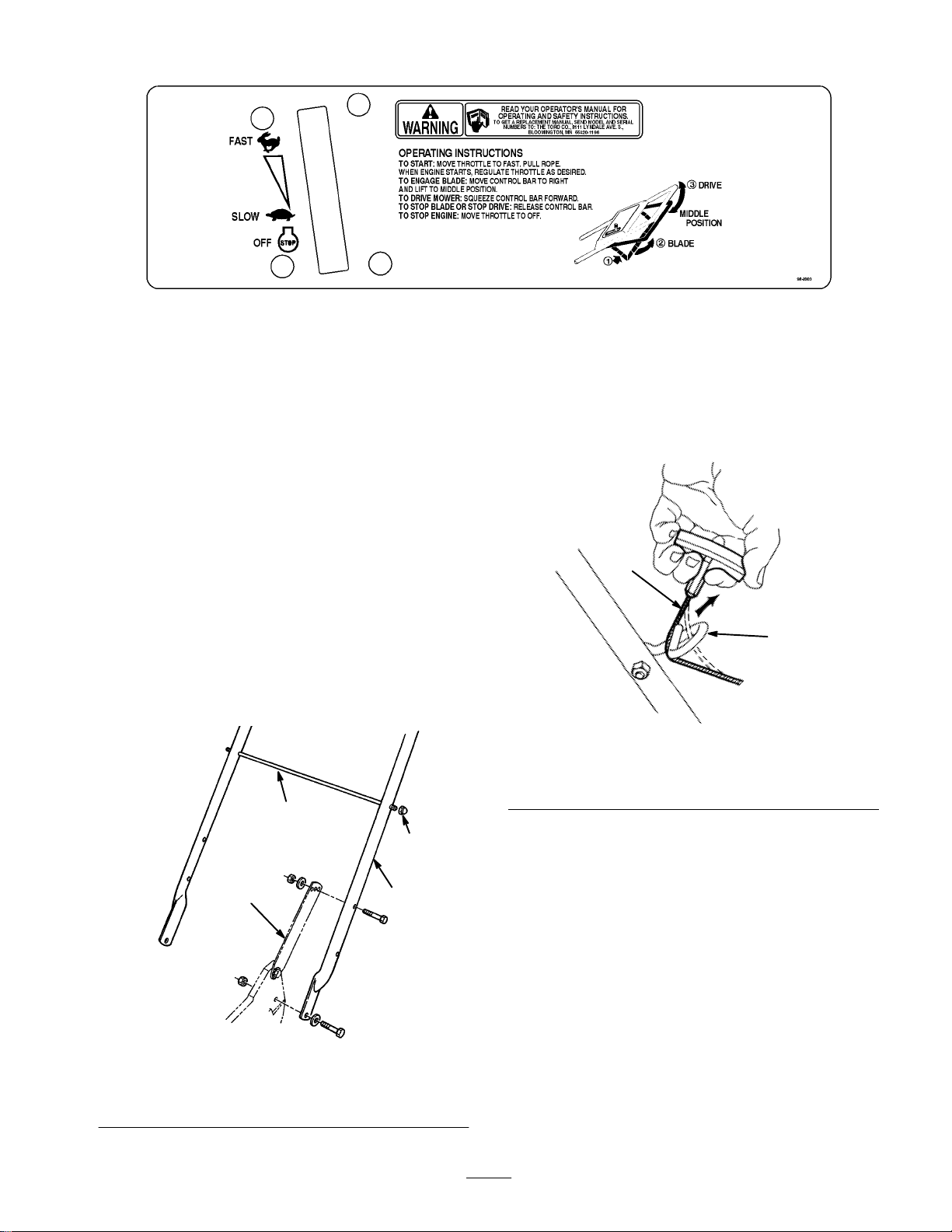
Handle
4. Use
a cable tie to secure the control cables to left
handle below the bag support rod.
5.
Pull starter rope through rope guide on handle (Fig. 3).
1. Mount
handle to outside of mower housing, using
bottom hole, with (2) 5/16–18 x 1–1/4” lg. capscrews,
washers, and thin nylon insert locknuts (Fig. 2).
2.
Secure handle latches to handle with (2) 5/16–18 x
1–1/2” lg. capscrews, washers and nylon insert
locknuts (Fig. 2).
Note:
Handle height is adjustable for operator comfort.
Stand behind mower handle to gauge height. T
o adjust
handle height, reposition capscrews and locknuts securing
handle latches to handle into other mounting holes in
latches.
Slide bag support rod thru
3.
top
mounting holes in
handle and secure each end with a cap locknut (Fig. 2).
2
3
1
4
1. Rope
guide
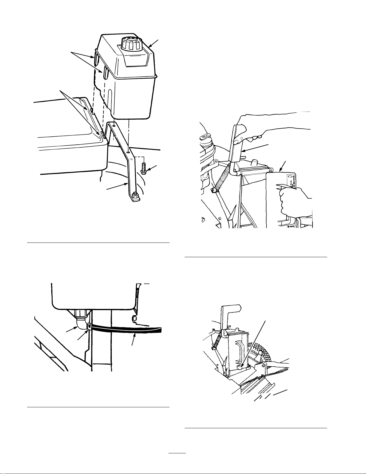
Gas Tank
1. Start
self-tapping screws into bottom of gas tank and
then remove screws.
2
1
m–210
Figure
3
2.
Starter rope
1. Handle
2.
Bag support rod
latch
Figure
2
3.
Cap locknut
4. Handle
534
2.
Hook plastic clips on front of gas tank into slots on
rear of engine (Fig. 4).
3.
Secure gas tank to tank base with (2) self-tapping
screws (Fig. 4). Do not overtighten screws.
5
Page 6
4
Discharge Tunnel Plug
3
2
1
Figure
4
1. Tank
2. Slots
3.
4. Remove
bracket
Plastic clips
red cap from end of fuel line and from end of
4.
Gas tank
5.
Self-tapping screw
elbow fitting on gas tank. Slide end of fuel line onto
elbow fitting (Fig. 5). Secure fuel line in place with
fuel line clamp.
1. Open
the dischar
ge door by pulling forward on the
handle and moving it rearwards (Fig. 6). Hold the
dischar
ge door handle to prevent the spring-loaded
door from closing while inserting the plug.
2.
Since the plug is slightly wider than the dischar
ge
tunnel opening, rotate the plug clockwise slightly
while inserting it (Fig. 6). Make sure the arrow on the
plug decal is pointing upwards.
1
2
5
530
m–262
1. Discharge
3. Push
the plug all the way in until the spring clip on the
Figure
door handle
6
2.
Plug rotated clockwise
bottom of the plug clicks into place, locking the plug
securely into the dischar
dischar
ge door handle to lock top of plug.
ge tunnel (Fig. 7). Release
1. Fuel
2.
Fuel line
3
line clamp
1
Figure
5
3.
Elbow fitting
1
2
2045
m–275
7
1. Spring
Figure
clip
6
Page 7
Before
Fill
Crankcase W
Fill
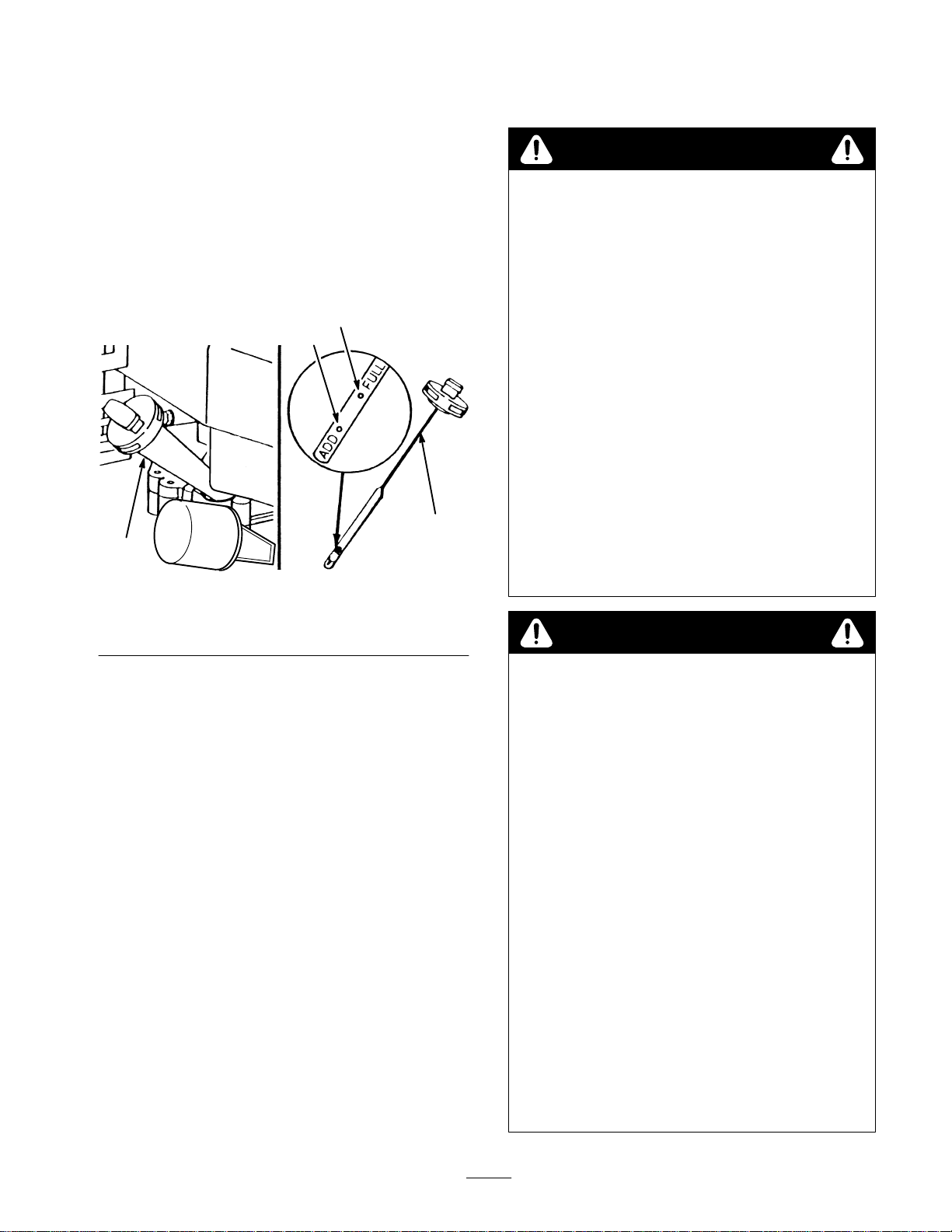
crankcase with SAE 30 or 10W30 oil until oil level
reaches FULL mark on dipstick as shown in (Fig. 8). The
maximum crankcase capacity is 26 ounces (0.77 liters) of
oil with the oil filter installed and 22 ounces (0.65 liters)
without the oil filter installed. Use any high quality
deter
gent oil having the American Petroleum Institute
(API) “service classification” — SF
1
1. Oil
fill tube
2. Dipstick
Starting
ith Oil
, SG, SH or SJ.
4
3
Figure
8
ADD mark
3.
4.
FULL mark
2
m–3845
Fill
Fuel T
ank W
ith Gasoline
DANGER
POTENTIAL
•
In certain conditions gasoline is extr
flammable and highly explosive.
WHA
T CAN HAPPEN
•
A fir
others, and cause pr
HOW T
•
Use a funnel and fill the fuel tank outdoors, in
an open ar
any gasoline that spills.
•
Do not fill the fuel tank completely full. Add
gasoline to the fuel tank until the level is 1/4” to
1/2” (6 mm to 13 mm) below the bottom of the
filler neck. This empty space in the tank allows
gasoline to expand.
•
Never smoke when handling gasoline, and stay
away fr
fumes may be ignited by a spark.
• Stor
keep it out of the r
•
Never buy mor
gasoline.
HAZARD
e or explosion fr
O AVOID THE HAZARD
ea, when the engine is cold. W
om an open flame or wher
e gasoline in an appr
om gasoline can burn you,
operty damage.
oved container and
each of childr
e than a 30-day supply of
emely
e gasoline
en.
DANGER
ipe up
Before
each use, ensure oil level is between ADD and
FULL marks on dipstick (Fig. 8). Add oil if level is low
Position mower on level surface and clean around oil
1.
dipstick.
Remove dipstick by rotating cap counterclockwise 1/4
2.
turn.
ipe dipstick and insert it into filler neck. Rotate cap
3. W
clockwise 1/4 turn. Then remove dipstick and check
level of oil (Fig. 8). If level is low
to raise level to FULL mark on dipstick.
FILL ABOVE FULL MARK BECAUSE ENGINE
COULD BE DAMAGED WHEN ST
POUR OIL SLOWL
Insert dipstick into filler neck and rotate cap clockwise
4.
1/4 turn to lock.
Note:
Check oil level each time mower is used or after
every 5 operating hours. Initially, change oil after the first
5 hours of operation; thereafter
hours of operation. More frequent oil changes are required
in dusty or dirty conditions.
Y.
, add only enough oil
DO NOT
ARTED.
, change oil after every 50
.
POTENTIAL HAZARD
•
When fueling, under certain cir
static charge can develop, igniting the gasoline.
WHA
T CAN HAPPEN
•
A fir
e or explosion fr
and others and cause pr
HOW T
•
•
•
•
•
O AVOID THE HAZARD
Always place gasoline containers on the gr
away from your vehicle befor
Do not fill gasoline containers inside a vehicle
or on a truck or trailer bed because interior
carpets or plastic truck bed liners may insulate
the container and slow the loss of any static
charge.
When practical, r
equipment fr
the equipment with its wheels on the r
If this is not possible, then refuel such
equipment on a truck or trailer fr
container
dispenser nozzle.
If a gasoline dispenser nozzle must be used,
keep the nozzle in contact with the rim of the
fuel tank or container opening at all times until
fueling is complete.
om the truck or trailer and r
, rather than fr
om gasoline can burn you
operty damage.
emove gas-power
om a gasoline
cumstances, a
e filling.
ed
ound.
om a portable
ound
efuel
7
Page 8
This engine is certified to operate on unleaded gasoline.
T
oro strongly recommends the use of fresh, clean,
UNLEADED
of 85 or higher in T
Unleaded gasoline burns cleaner
promotes good starting by reducing the build-up of
combustion chamber deposits. In countries other than
U.S.A., leaded gasoline may be used if it is commercially
available and unleaded is unavailable.
regular grade gasoline with an octane rating
oro gasoline powered products.
, extends engine life, and
IMPORTANT
use gasoline that has been stor
container fr
T
oro also recommends that T
used regularly in all T
during operation and storage seasons. T
Stabilizer/Conditioner cleans the engine during operation
and prevents gum-like varnish deposits from forming in
the engine during periods of storage.
IMPORTANT
r
eformulated gasolines, ar
alcohols or ethers. Excessive amounts of these blends
can damage the fuel system or cause performance
pr
oblems. Never use methanol
methanol
or white gas because engine fuel system damage could
r
esult. If any undesirable operating symptoms occur
use gasoline with a lower per
ether.
Do not use fuel additives other than those
manufactur
as T
oro’
s Stabilizer/Conditioner is a petr
Toro’
based conditioner/stabilizer
stabilizers with an alcohol base such as ethanol,
methanol or isopr
try to enhance the power or performance of machine.
1.
Clean around fuel tank cap and remove cap from tank.
Using unleaded gasoline, add fuel to 1/4” to 1/2” (6 to
13 mm) from top of tank, not into the filler neck. Do
not fill the tank full.
2.
Reinstall fuel tank cap and wipe up any spilled
gasoline.
Connect spark plug wire (if disconnected) (Fig. 9).
3.
: Do not mix oil with the gasoline. Do not
ed in an appr
om one season to the next.
oro Stabilizer/Conditioner be
oro gasoline powered products
: Some fuels, called oxygenated or
e gasolines blended with
, gasoline containing
, gasohol containing mor
ed for fuel stabilization during storage such
s Stabilizer/Conditioner or a similar pr
opyl. Additives should not be used to
e than 10% ethanol
centage of alcohol or
. Toro does not r
oved
oro
oleum distillate
ecommend
,
oduct.
1 2
Figure
1. Primer 2. Spark
Recycling
T
9
plug wire
ips
General Tips
Follow
these instructions whether cutting grass or leaves
for the best cutting results and lawn appearance:
•
Maintain a
Periodically file down nicks on blade.
•
Only mow dry grass or leaves. Wet grass and leaves
tend to clump on yard and may cause mower to plug or
engine to stall. They also may be slippery to walk on
and could cause you to slip and fall.
POTENTIAL HAZARD
• W
et grass or leaves can cause you to slip and
contact blade.
WHA
•
Blade contact can seriously injure you.
HOW T
•
Mow only in dry conditions.
sharp blade
throughout the cutting season.
WARNING
T CAN HAPPEN
O AVOID THE HAZARD
m–3662
•
Set engine speed to fastest position. Maximum
horsepower provides best cutting results.
•
Clean clippings or leaves from underside of mower
deck after each mowing.
•
Keep engine in good running condition. Cutting and
recutting requires more horsepower
8
.
Page 9

•
Clean air filter more frequently
stirs up more clippings and dust which clogs the air
filter and reduces engine performance.
. Cutting and recutting
Cutting Grass
• Grass
grows at dif
year
. In the heat of the summer
cut grass at the 1settings (Fig. 10). Only about
should be cut of
not recommended unless grass is sparse or it is late fall
when grass growth begins to slow down.
ferent rates at dif
#/4
”, 2-
!/4
f. Cutting below the 1-
#4!4#4!4
ferent times of the
, it is generally best to
” or 2-
#/4
” height-of-cut
!/3
of the grass blade
#/4
” setting is
Overlap cutting swaths instead of cutting a full swath
•
with each pass.
•
Mow across the mar
•
Set height-of-cut on front wheels one notch lower than
rear wheels. (example: set front wheels at 1setting and rear wheels at 2-
ginal areas a second time.
!/4
” setting)
#/4”
Cutting Leaves
• When
#4!4
•
•
• W
•
cutting is complete, always be sure that 50% of
the lawn shows through the cut leaf cover
require one or more passes over the leaves.
For light leaf coverage, position all wheels at the same
height-of-cut setting.
If there are more than five inches of leaves on lawn,
set the front wheels one or two notches higher than the
rear wheels. This makes it easier to feed leaves under
mower deck.
alk at a slower mowing speed if leaves are not being
cut up finely enough to be hidden down in the grass.
If you cut up a lot of oak leaves, you might want to
add lime to your grass in the spring. Lime reduces the
acidity of oak leaves.
. This may
Figure
• When
•
If the finished cut lawn appearance is unsatisfactory
one or more of the following:
•
• W
•
•
cutting grass over six inches tall, you may want
to first mow using the highest height-of-cut setting and
a slower walking speed; then mow again at a lower
setting for best lawn appearance. If grass is too long
and leaves clumps on top of lawn, mower may plug
and cause engine to stall.
Alternate mowing direction. This helps disperse
clippings over lawn for even fertilization.
Sharpen the blade.
alk at a slower pace while mowing.
Raise the height-of-cut setting on your mower
Cut grass more frequently
10
.
.
, try
976
Operation
Operating Tips
1. CHECK
ADD and FULL marks as shown on dipstick (Fig. 8).
2.
BEFORE EACH MOWING—Be sure blade brake,
self-propelled drive, and control bar function properly
When control bar is released, blade and self-propelled
drive are designed to stop. If controls are not
functioning properly
are repaired.
3.
SHARP BLADE—Begin each cutting season with a
sharp blade. Periodically file down nicks.
Controls
Throttle control, blade/self-propelled control bar and
fingertip starter are on upper handle (Fig. 1
speed control is located at rear of belt cover (Fig. 12).
OIL LEVEL—Maintain oil level between
, do not use mower until controls
1). Ground
.
9
Page 10

1
1. Blade/self-propelled
control
bar
Figure 11
2. Throttle
3.
Fingertip starter
Note:
Do not use primer to restart a warm engine after a
short shutdown. However
priming to be repeated.
5.
Pull recoil starter out until positive engagement
2
3
1992
results; then pull vigorously to start the engine. Allow
the engine to warm-up. During warm-up, the
equipment can be operated. Regulate throttle as
desired when engine starts. Move ground speed control
to desired setting.
6.
BLADE AND TRACTION OPERA
(Fig. 13)—When control bar is in position “A”, slide
control bar to right and raise to position “B” to engage
blade. Squeeze control bar against handle to position
“C” to drive. T
blade engaged, gradually release control bar to
position “B”. T
simply squeeze control bar against handle to position
“C”, without sliding control bar to right.
, cool weather may require
TION
o disengage traction drive but keep
o self-propel with blade disengaged,
1
1. Ground
speed control
Starting,
Figure
Stopping, and
12
Self-propelling
Note:
The engine requires a warm-up period of one
minute to several minutes, depending on the temperature.
1.
Push spark plug wire onto spark plug (Fig. 9).
2.
Move throttle control to
3.
Move ground speed control to
4.
Push primer three (3) times (Fig. 9). Wait about two
(2) seconds between each push.
(F
AST) position.
(NEUTRAL).
224
Figure
13
7. STOPPING—To
move throttle control to
plug if mower will be unattended or not used.
Using
1. Make
pulling forward on the handle and moving it rearwards
(Fig. 6). Hold the dischar
spring-loaded door from closing while inserting the
plug.
Since the plug is slightly wider than the dischar
2.
tunnel opening, you must rotate the plug clockwise
slightly while inserting it (Fig. 6). Make sure the arrow
on the plug decal is pointing upwards.
Discharge T
sure engine is of
stop engine, release control bar and
(OFF). Pull wire of
unnel Plug
f. Open the dischar
ge door handle to prevent the
ge door by
m-3769
f spark
ge
10
Page 11

3.
Push the plug all the way in until the spring clip on the
bottom of the plug clicks into place, locking the plug
securely into the dischar
dischar
ge door handle to lock the top of the plug.
4. T
o remove the plug, move the dischar
ge tunnel (Fig. 7). Release the
ge door handle
rearwards while at the same time lift up the spring clip
on the bottom of the plug. When the plug is unlocked,
pull it out of the dischar
Note:
When grass is thick and lush, clippings may collect
ge tunnel.
on and around the discharge tunnel plug. This may make
plug removal dif
use. Refer to Cleaning Mower
Using
ficult. Clean plug thoroughly after each
, page 17.
Grass Bag
DANGER
POTENTIAL
•
Grass clippings and other objects can be
thr
own fr
WHA
T CAN HAPPEN
•
Objects thrown with enough for
serious personal injury or death to operator or
bystander.
HOW T
•
Never open door on discharge tunnel when
engine is running unless the grass bag, optional
side discharge attachment or discharge tunnel
plug is secur
HAZARD
om an open discharge tunnel.
ce could cause
O AVOID THE HAZARD
ely installed.
Occasionally
you may wish to use the grass bag for
bagging extra long grass, lush grass or leaves.
1.
Stop engine and wait for all moving parts to stop.
2.
Ensure dischar
ge door handle is fully forward and pin
is engaged in catch (Fig. 14).
3. INST
ALLING BAG—Slide hole in bag frame onto
retaining post on dischar
ge tunnel (Fig. 14). Set rear of
bag frame onto lower handle.
2
1
4.
Pull dischar
ge door handle forward until pin clears
catch and move handle rearward until pin locks in bag
notch (Fig. 15). Dischar
ge door in mower housing is
now open.
1
15
Figure
1. Pin
locked in bag notch
m–260
1. Bag
frame on retaining
post
2.
Pin engaged in catch
3
Figure
14
3.
Handle fully forward.
Discharge door closed.
m–261
11
Page 12

DANGER
POTENTIAL
•
A worn grass bag could allow small stones and
other similar debris to be thrown in operator
or bystander’s dir
WHA
T CAN HAPPEN
• Thr
own objects can cause serious personal
injury or death to operator or bystanders.
HOW T
•
Check the grass bag fr
damaged, install a new genuine T
eplacement bag.
r
HAZARD
ection.
O AVOID THE HAZARD
equently
. If it is
ORO
DANGER
POTENTIAL HAZARD
• Thr
own objects may r
does not close completely
WHA
T CAN HAPPEN
• Thr
own objects can cause serious
personal injury or death.
HOW T
•
5.
6. T
O AVOID THE HAZARD
If discharge door cannot be closed because
grass clippings clog discharge ar
and gently move discharge door handle back
and forth until door can be closed completely
door still cannot be closed, r
with a stick, not your hand.
EMPTYING BAG—Stop engine and wait for all
moving parts to stop. Raise dischar
move it forward to engage the locking pin with the
catch (Fig. 14). Grasp handles at front and rear of bag
and lift bag of
empty clippings.
o reinstall bag, repeat steps 3-4.
f mower
esult if discharge door
.
ea, stop engine
emove obstruction
ge door handle and
. Gradually tip bag forward to
’s
. If
2.
For easier adjustment, lift housing up so wheel is of
ground. Do not place hands under deck to lift
housing.
(Fig. 16) and move it to the desired setting. Assure pin
on adjusting lever engages notch in mower housing
wear plate. Adjust all wheels to the same setting.
Squeeze adjusting lever toward wheel
DANGER
POTENTIAL HAZARD
•
Adjusting height-of-cut levers could bring
hands into contact with moving blade.
WHA
T CAN HAPPEN
•
Contact with blade could cause serious
personal injury
HOW T
•
•
1. Height-of-cut
O AVOID THE HAZARD
Stop engine and wait for all moving parts to
stop befor
Do not put fingers under housing to lift mower
when adjusting height-of-cut levers.
.
e changing height-of-cut.
Figure
16
adjuster
1
f
225
Adjusting
The
height-of-cut is adjustable from approximately
3-!/4
inches (19 mm to 83 mm), in
increments (Fig. 10). Moving height-of-cut adjuster
forward raises height-of-cut.
1.
Stop the engine and wait for all moving parts to stop.
Pull wire of
Height-of-cut
!/2
f spark plug (Fig. 9).
inch (12.7 mm)
#/4
to
Maintenance
NOTICE:Maintenance, replacement or r
emission contr
performed by any nonr
or individual. However
under the terms and pr
statement, any service or emission contr
or r
eplacement must be performed by an Authorized
Tor
o Service Dealer
12
ol devices and systems may be
oad engine r
, to obtain no charge r
ovisions of the Toro warranty
.
epair of the
epair establishment
epairs
ol part r
epair
Page 13

CAUTION
POTENTIAL HAZARD
•
When wir
accidentally start the engine.
WHA
•
Accidental starting of engine could cause
serious injury to operator or bystanders.
HOW T
•
Pull wir
maintenance. ALso push wir
not accidentally contact spark plug.
e is on spark plug, someone could
T CAN HAPPEN
O AVOID THE HAZARD
e off spark plug befor
e you do any
e aside so it does
Carefully remove pre-cleaner
4.
carefully wash it in a solution of liquid soap and warm
water
. Rinse in clear water
before using.
5.
If paper cartridge is dirty
tapping it
cartridge.
IMPORTANT
cartridge. Do not use pr
cartridge.
Reinstall pre-cleaner over paper cartridge. Reinstall air
6.
cleaner cover and tighten securely in place with two
(2) knobs.
gently
on a flat surface. If very dirty
: Do not oil pr
. If pre-cleaner is dirty
. Allow to dry thoroughly
, clean the paper filter by
e-cleaner or paper
essurized air to clean paper
,
, replace
Servicing
Normally,
operating hours or every season. Clean the paper cartridge
after every 100 hours or every season. More frequent
cleaning is required when mower is operated in dusty or
dirty conditions. Replace air cleaner parts, if very dirty
IMPORTANT
elements; extr
Note: T
of mower may cause damage to air filters.
1.
2.
clean air cleaner pre-cleaner after every 25
ipping mower on wrong side to service underside
Stop engine and pull wire of
Loosen two (2) knobs securing air cleaner cover to
engine (Fig. 17).
Air Cleaner
.
: Do not operate engine without air filter
eme engine wear or damage will occur
f spark plug (Fig. 9).
1
.
2
Replacing
Remove
condition. Replace spark plug every 100 operating hours
or every season. Use a Champion RC12YC spark plug or
equivalent.
1.
2.
IMPORTANT
spark plug. Do not sand blast, scrape, or clean
electr
grit entering cylinder
3.
plug after every 25 operating hours and check its
Stop engine and wait for all moving parts to stop. Pull
wire of
f spark plug (Fig. 9).
Clean around spark plug and remove plug from
cylinder head.
odes because engine damage could r
Set air gap at 0.020” (0.5 mm) (Fig. 18). Install
correctly gapped spark plug and gasket seal. T
plug firmly to 14 ft–lb (19 N
Spark Plug
: Replace a cracked, fouled, or dirty
esult fr
.
ighten
m).
1
om
3
1. Knob
2. Cover
3. Lift
cover of
Figure
f. Clean cover thoroughly
17
3. Foam
4.
Paper cartridge
4
pre-cleaner
.
m–3664
1. .020
Draining
1. Stop
spark plug (Fig. 9).
Note:
13
Figure
18
in. (0.5 mm)
Gasoline
engine and wait for engine to cool. Pull wire of
Drain gasoline from a cold engine only
.
110
f
Page 14

2.
Remove cap from fuel tank and use pump-type syphon
to drain fuel into clean gas can.
Note:
This is the only procedure recommended for
draining fuel.
4.
Remove oil filter and discard it.
5.
Using your finger
with oil (Fig. 20).
, coat the gasket on the new filter
1
Changing
Change
oil after the first 5 operating hours and then after
every 50 hours or every season. Change oil while engine
is warm.
Note:
Change oil every 25 hours when operating under
heavy load or in high temperatures.
1.
Stop engine and wait for all moving parts to stop. Pull
wire of
f spark plug (Fig. 9).
2.
Remove grass bag. Drain gasoline from fuel tank: refer
to Draining Gasoline, page 13.
3.
Remove dipstick from oil fill tube and place a drain
pan next to left side of mower
ip mower on its left side, allowing oil to drain into
4. T
drain pan (Fig. 19).
1
Crankcase Oil
.
20
Figure
1. Gasket
6. Install
7.
8.
Adjusting
Throttle
does not start. Whenever a new throttle control cable is
installed, throttle must be adjusted.
1.
the new filter and hand tighten it 2/3 turn only
Check the filter for any oil leaks.
Properly discard the oily rag.
Throttle
control adjustment may be required if engine
Stop engine and wait for all moving parts to stop. Pull
wire of
f spark plug (Fig. 9).
m-3862
.
Figure
1. Oil
fill tube
5. When
Replacing
Replace
hours or yearly
1.
2.
3.
oil is drained, return mower to upright position
and add fresh oil to engine. Refer to Fill Crankcase
W
ith Oil, page 7.
Oil Filter
the oil filter (Fig. 19) after every 100 operating
, whichever occurs first.
Drain gasoline from fuel tank; refer to Draining
Gasoline, page 13.
Drain oil. Refer to Changing Crankcase Oil, page 14.
Place a rag under oil filter to catch any oil that may
leak out as filter is removed.
19
2.
Oil filter
2
m–3848
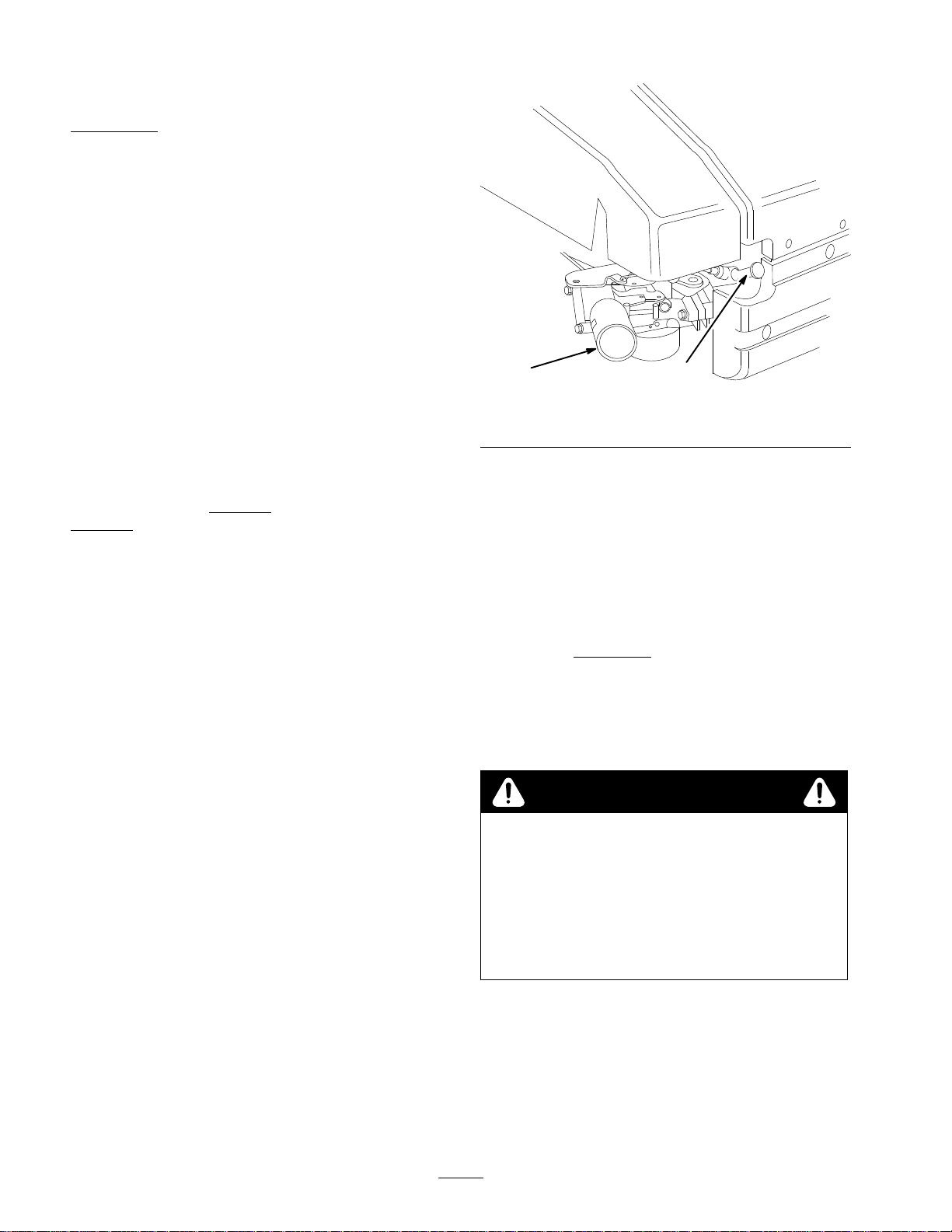
2.
Loosen cable clamp screw until throttle cable slides
(Fig. 21).
3.
Move governor control lever
in direction of arrow as far as possible (Fig. 21).
Figure
1. Cable
2.
4. Move
5. T
clamp screw
Governor control lever
throttle control to
ighten cable clamp screw to lock adjustment in place.
, throttle cable and casing
21
3.
Throttle cable
4. Casing
(F
AST position).
m-3638
14
Page 15
Cleaning
After
every 100 operating hours, clean dirt and chaf
cylinder
and linkage. Also remove debris from air intake slots on
recoil housing. This will ensure proper cooling and
optimum engine performance.
, cylinder head fins and from around carburetor
Cooling System
f from
1
Adjusting
If
mower does not self-propel or self-propels when control
bar is
more
wheel drive control knob on rear of gear box.
1.
Close door in mower housing and remove grass bag.
2.
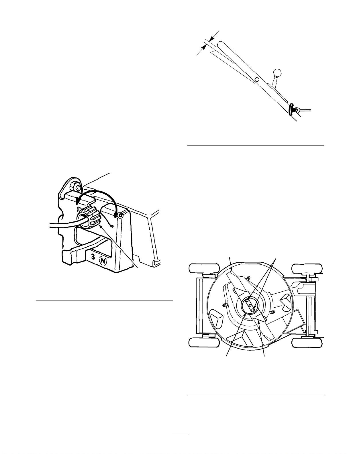
ADJUSTMENT (Fig. 22)—Rotate control knob
clockwise 1/2 turn if mower does not self-propel. If
mower creeps forward, rotate knob 1/2 turn
counterclockwise to loosen belt.
Wheel Drive
than 1–1/2 inches from the handle, adjust
m–1992
Figure
23
1. One
inch
Inspecting/Removing/
Sharpening
Always
mow with a sharp blade. A sharp blade cuts
cleanly and without tearing or shredding the grass blades
like a dull blade.
1.
Stop engine and wait for all moving parts to stop. Pull
wire of
f spark plug (Fig. 9).
2.
Drain gasoline from fuel tank; refer to Draining
Gasoline, page 13.
3. T
ip mower on its left side (Fig. 24).
Blade
1
2
1
Figure
1. Control
3. CHECK
knob
ADJUSTMENT—Slowly pull mower
backward while control bar is gradually moved toward
handle. Adjustment is correct when rear wheels stop
turning and control bar is about 1 inch from handle
(Fig. 23).
22
228
1. Blade
2. Blade
nuts
3
Figure
4
24
3.
Anti-scalp cup
4. Accelerator
796
15
Page 16

CAUTION
POTENTIAL
•
Someone could accidentally start the engine.
WHA
T CAN HAPPEN
•
Accidental starting of engine could cause
serious injury to operator or bystanders.
HOW T
•
Do not attempt to inspect, r
blade without first r
wir
e fr
fr
om accidental contact with spark plug.
4.
INSPECTING BLADE—Carefully examine blade for
sharpness and wear
parts meet (Fig. 25A). Since sand and abrasive
material can wear away the metal that connects the flat
and curved parts of the blade, check blade before using
the mower. If a slot or wear is noticed, (Fig. 25B & C),
replace blade. Refer to step 5.
HAZARD
O AVOID THE HAZARD
emove or r
eplace
emoving the spark plug
om spark plug and fastening it away
, especially where flat and curved
5.
REMOVING BLADE—Grasp end of blade using a rag
or thickly padded glove. Remove blade nuts, anti-scalp
cup, accelerator
6.
SHARPENING BLADE—Using a file, sharpen top
, and blade (Fig. 24).
side of blade and maintain original cutting angle
(Fig. 26). The blade will remain balanced if same
amount of material is removed from both cutting
edges.
1
Figure
26
1. Sharpen
at this angle only
153
2
3
Figure
1. Sail
2. Flat
part of blade
Note:
For best performance, install new blade before
cutting season begins. During the year
25
3. Wear
4.
Slot formed
, file down small
nicks to maintain the cutting edge.
DANGER
POTENTIAL HAZARD
•
A worn or damaged blade could br
piece of blade could be thr
or bystander’s ar
WHA
T CAN HAPPEN
•
A thr
own piece of blade could cause serious
ea.
own into operator
personal injury or death to operator or
bystanders.
HOW T
•
•
O AVOID THE HAZARD
Inspect blade periodically for wear or damage.
Replace a worn or damaged blade.
eak and a
IMPORTANT:
1
a blade balancer
pur
chased at a hardwar
Check balance of blade by putting it on
. An inexpensive balancer can be
e stor
e. A balanced blade stays
in a horizontal position and an unbalanced blade settles
1
to the heavy side. If blade is not balanced, file mor
metal off cutting edge on heavy end of blade.
7.
Reinstall sharp, balanced blade, blade accelerator
e
,
anti-scalp cup, and blade nuts. Sail part of blade must
1
4
270
point toward top of mower housing to assure correct
installation. T
ighten blade nuts to 15–27 ft–lbs (20–37
Nm).
WARNING
POTENTIAL HAZARD
•
Operating mower without accelerator in place
could cause blade to flex, bend or br
WHA
T CAN HAPPEN
•
A broken blade could cause serious injury or
eak.
death to operator or bystanders.
HOW T
•
O AVOID THE HAZARD
Do not operate mower without accelerator
.
’s
Lubrication
After every 25 operating hours or when season ends, pivot
arms must be lubricated.
1.
Move rear wheel height-of-cut levers to center setting.
W
ipe grease fittings with clean rag (Fig. 27). Install
grease gun onto fitting and gently apply 2 or 3 pumps
of #2 Multi-Purpose Lithium Base Grease. Excessive
grease pressure may damage seals.
16
Page 17

1.
Stop engine and wait for all moving parts to stop. Pull
wire of
f spark plug (Fig. 9).
2.
Loosen cable clamp screw until brake cable conduit
slides (Fig. 29). Pull cable to remove slack, but do not
put tension on spring. T
adjustment in place.
1
ighten screw to lock
2
Figure
1. Grease
Lubricating
After
#2 Multi-Purpose Lithium Base Grease.
1.
2.
3.
1. Grease
fitting
Gear Case
every 100 operating hours, grease the gear case with
Remove bag.
Install grease gun onto fitting thru belt cover opening
(Fig. 28). Gently apply 1–2 pumps of grease.
Reinstall bag.
1
2
Figure
fitting
27
28
2.
Belt cover
232
224
1
29
Figure
1. Spring
2. Cable
clamp screw
3.
Cable conduit
WARNING
POTENTIAL
•
Do not over
Over
pulled off brake drum. If brake does not
contact drum, blade will not stop r
contr
WHA
T CAN HAPPEN
•
A r
otating blade could cause serious personal
injury.
HOW T
•
Check the blade brake mechanism each time
brake cable is adjusted to ensur
stopping blade in 3 seconds or less.
•
If blade does not stop rotating in 3 seconds or
less, bring unit to your local Authorized T
Service Dealer for inspection and r
Cleaning
HAZARD
-tighten blade brake cable.
-tightening could cause blade brake to be
ol bar is r
O AVOID THE HAZARD
eleased.
e brake is
Mower
3
278
otating when
oro
epair.
Adjusting
Whenever
or the blade brake belt is replaced, the blade brake cable
should be adjusted.
a new blade brake cable assembly is installed
Blade Brake Cable
Plug
To
ensure best performance, the dischar
must be cleaned after each use. When grass is thick and
lush, clippings may collect on and around the plug; this
may make plug removal dif
plug from dischar
ge tunnel and clean of
ficult. After each use, remove
17
ge tunnel plug
f all debris.
Page 18
Discharge Tunnel
Always
be sure that dischar
ge tunnel door closes securely
when handle is released. If debris prevents dischar
from closing securely
door thoroughly
, clean inside of dischar
.
ge tunnel and
WARNING
POTENTIAL HAZARD
•
Grass clippings and other objects can be
thr
own fr
om an open discharge tunnel.
WHA
T CAN HAPPEN
• Thr
own objects can cause serious injury or kill
operator or bystanders.
HOW T
•
Underside of Mower Housing
Keep
careful to keep kickers free of debris (Fig. 30).
O AVOID THE HAZARD
Never start or operate the mower unless one
the following is true:
1.
The discharge tunnel plug is locked secur
in discharge tunnel.
2.
The grass bag is locked in place.
3.
The optional side discharge chute is locked
in place.
4.
The discharge tunnel door is closed.
underside of mower housing clean. Be especially
ge door
of
ely
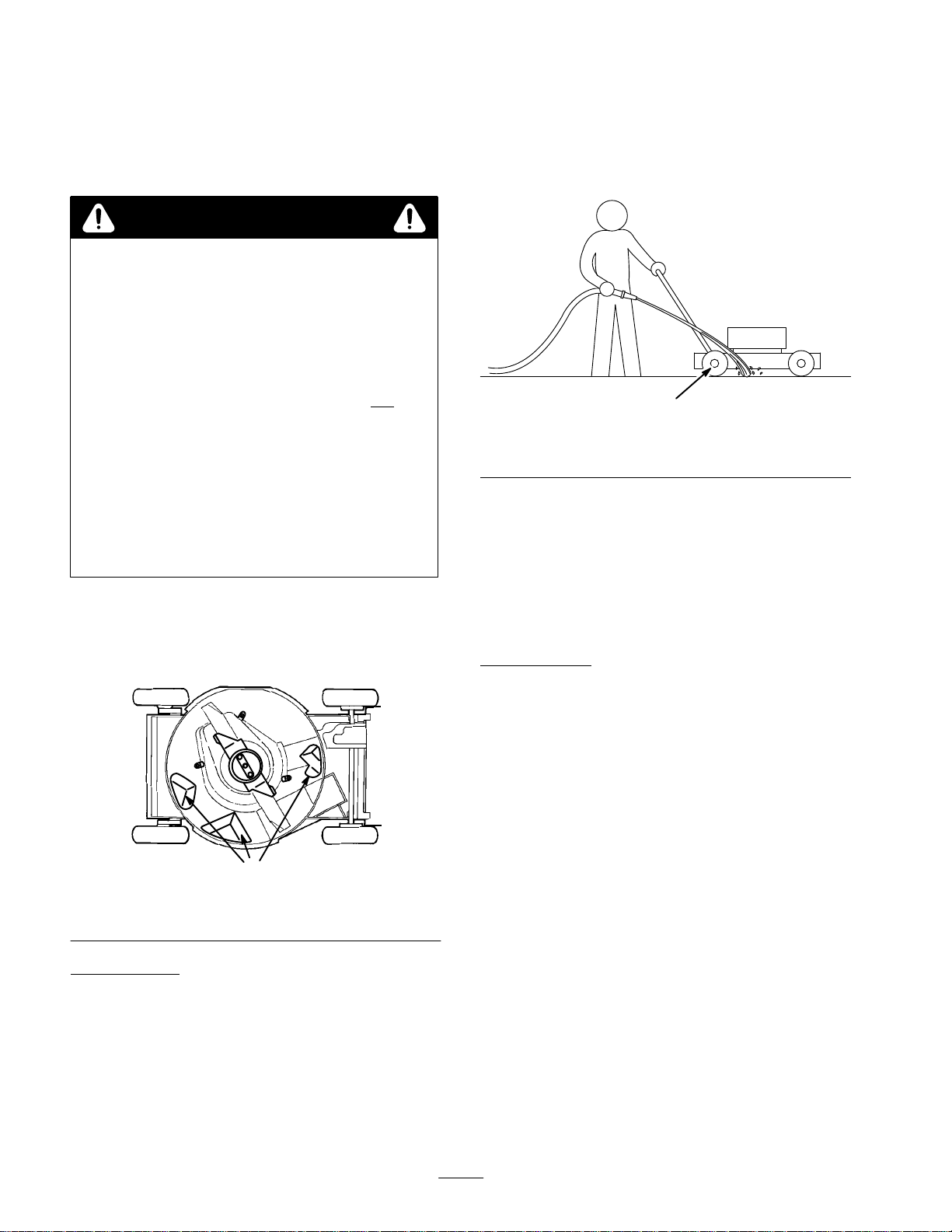
4.
Hold the running garden hose at handle level and
direct water to flow on ground just in front of right
rear tire (Fig. 31). The rotating blade will draw water
under the deck and wash out clippings. Let the water
run for a few minutes or until you no longer see
clippings being washed out from under deck.
Figure
31
1. Right
5. Disengage
6. T
7.
rear wheel
the blade.
urn of
f the garden hose.
Restart mower and let it run for a few minutes to dry
1093
out moisture on the mower and its components. While
the engine is running, engage and disengage the safety
system and traction drive several times to dry them
out.
Scraping Method
If washing does not remove all debris from under deck, tip
mower and scrape it clean.
30
1. Kicker
Washing
Figure
plates
Method
After every use, follow this procedure for washing debris
out from the underside of the mower housing.
1.
Position mower on a flat surface near a garden hose.
2.
Start the engine.
3.
Engage the blade.
796
1.
Pull wire of
2.
Drain gasoline from fuel tank: refer to Draining
f spark plug (Fig. 9) .
Gasoline, page 13.
3. T
ip mower on its left side (Fig. 30).
4.
Remove dirt and grass clippings with a hardwood
scraper
. A
void burrs and sharp edges.
5. T
urn mower upright.
6.
Refill gas tank.
7.
Reconnect spark plug wire.
Belt Cover
Keep
area under belt cover free of debris.
1.
Remove bolts securing belt cover (Fig. 28) to mower
housing. Lift of
belt area. Reinstall belt cover
f cover and brush out all debris from
.
18
Page 19

Cleaning
Shield
Blade Brake Clutch
Servicing
Wheels (Fig. 33)
The
BBC (Blade Brake Clutch) shield should be cleaned
periodically during the mowing season and at the end of
each mowing season to ensure best performance and to
prevents parts degradation. It is convenient to clean the
BBC shield at the same time the blade is being sharpened
because the blade needs to be removed in order to remove
the BBC shield.
1.
Stop engine and wait for all moving parts to stop. Pull
wire of
f spark plug (Fig. 9).
2.
Drain gasoline from fuel tank; refer to Draining
Gasoline, page 13.
3. T
ip mower on its left side.
4.
Remove (2) blade nuts, anti-scalp cup, accelerator
, and
blade (Fig. 24).
5.
Loosen tabs securing BBC shield to deck by loosening
nuts or bolts on tabs (Fig. 32). Rotate tabs 180_ to
move them out of the way
.
Figure
33
1. Locknuts
2. Wheel
3.
4.
5.
spacer
Bearing/hub assembly
Bearing spacer
Wheel half
6.
Plastic cover (rear
wheels only)
7. Lug
8.
Bearing (2)
9. Capscrew
Removal
1. Stop
2.
engine and wait for all moving parts to stop. Pull
wire of
f spark plug (Fig. 9).
Remove capscrew
, wheel spacer
, and locknut
mounting wheel to pivot arm.
296
32
3. T
ab and bolt
1. BBC
2. T
shield
abs and nuts
6. Remove
Figure
BBC shield and brush or blow all debris from
under shield and around BBC system.
7.
Reinstall BBC shield. Rotate tabs 180_ back into
position. T
ighten nuts or bolts on tabs to secure BBC
shield to deck.
8.
Reinstall blade, accelerator
, anti-scalp cup, and (2)
blade nuts.
9. T
urn mower upright.
10.
Reinstall spark plug wire on spark plug.
796
3.
Separate wheel halves from tire by removing (4)
capscrews and locknuts.
Note:
If bearings are to be removed from bearing/hub
assembly
, remove by pressing on bearing spacer
.
Assembly
1.
Position tire onto (1) wheel half, aligning lugs on each.
2.
Place bearing/hub assembly into center hole of wheel
half. Make sure legs of hub are positioned over flange
of hole.
3.
Place other wheel half onto bearing/hub assembly
aligning wheel and tire lugs and mounting holes.
4.
Using (2) 1/4—20 x 1.50” lg. fully threaded screws or
bolts and non-locking nuts, loosely secure wheel
halves together
holes.
Check alignment of all parts and tighten screws,
5.
alternating from side to side for a uniform fit, until
wheel halves are drawn together
Install (2) capscrews and locknuts, previously
6.
removed, in remaining holes in wheel halves and
tighten. Remove (2) long screws or bolts and replace
with (2) capscrews and locknuts.
. Mount screws or bolts in opposing
.
19
Page 20

7.
Reinstall wheel to pivot arm with capscrews, spacer
and locknut. Make sure spacer is positioned between
wheel hub and pivot arm.
Fuel
Filter
Replacing the Fuel Filter
Replace
yearly
fuel filter (Fig. 34) is when the fuel tank is empty
install a dirty filter if it is removed from the fuel line.
1.
1. Hose
2.
2. Remove
3.
the fuel filter after every 100 operating hours or
, whichever occurs first. The best time to replace the
. Never
Squeeze the ends of the hose clamps together and slide
them away from the filter (Fig. 34).
1
2
Fuel line
Install a new filter and move the hose clamps close to
the filter
3
Figure
clamp
the filter from the fuel lines.
.
2
34
3. Filter
,
m–3844
stabilizers with an alcohol base, such as ethanol,
methanol or isopropyl. Use fuel additive in
recommended quantities as specified on container
Under normal conditions, fuel additives remain
ef
fective in fuel for 6–8 months.
2.
Drain oil: refer to Changing Crankcase Oil, page 14.
After oil is drained, do not fill crankcase with oil until
the following steps (3–1
3.
Remove spark plug and pour 2 tablespoons of SAE 30
oil into hole in cylinder
coat inside of cylinder
14 ft–lb (19 Nm).
SP
ARK PLUG.
4.
Clean mower housing: refer to Cleaning Mower
page 17.
5.
Clean BBC shield: refer to Cleaning Blade Brake
Clutch Shield, page 19.
6.
Clean dirt and chaf
and blower housing. Also remove grass clippings, dirt,
and grime from external parts of the engine,
shrouding, and top of mower housing.
7.
Check condition of blade: refer to
Inspecting/Removing/Sharpening Blade, page 15.
8. T
ighten all nuts, bolts, and screws.
9.
Clean air cleaner: refer to Servicing Air Cleaner
page 13.
10.
Lubricate the pivot arms: refer to Lubrication,
page 16.
11. T
ouch up all rusted or chipped paint surfaces. T
Re-Kote paint is available from an Authorized T
Service Dealer
.
1) are completed.
. Pull starter rope slowly to
. Install spark plug and tighten to
DO NOT REINST
f from cylinder
ALL WIRE ON
, cylinder head fins,
.
,
,
oro
ORO
Storage
1.
For long term storage, either drain gasoline from fuel
tank or add a fuel stabilizer to the gasoline. T
gasoline, refer to Draining Gasoline, page 13. After
fuel is drained, start engine and let it idle until all fuel
is consumed and engine stops. Repeat the starting
procedure two more times to ensure all gas is removed
from the engine. If gasoline is not drained, gum-like
varnish deposits will form and cause poor engine
operation, even starting problems.
Note:
If engine is operating on oxygenated or
reformulated gasoline (gasoline blended with an alcohol
or an ether), remove all fuel from tank and run engine
until it stops from lack of fuel before storing.
Fuel can be left in gas tank only if a fuel additive, such
as T
oro’
s Stabilizer/Conditioner
and run through engine before storing. T
Stabilizer/Conditioner is a petroleum distillate based
conditioner/stabilizer. T
oro does not recommend
, is added to gasoline
o drain
oro’s
20
Fill crankcase with oil: refer to Fill Crankcase W
12.
Oil, page 7.
13.
Store mower in a clean, dry place, out of the reach of
children. Cover mower to keep it clean and protected.
ith
Page 21

Accessories
For special conditions, the following accessories may be
purchased at your local Authorized T
oro Service Dealer
.
Side Discharge Kit, Model No. 59199
1.
seconds. Rear mounted in place of the grass bag or
dischar
ge tunnel plug. Disperses clippings while
trimming on both sides (Fig. 35).
Figure
1. Side
2. Spark
discharge chute
Arr
estor and Scr
spark arrestor is required because of local, state, or
federal regulations, it may be purchased at your local
Authorized T
every 75 hours of operation. If mower is operated on
any California forest, brush, or grass covered land
without a properly operating spark arrestor
operator is violating state law
Resources Code.
ORO Service Dealer
35
ew (Part No. 94–1681)
, Section 4442 Public
—Installs in
. Clean screen after
, the
2047
—If a
21
Page 22

Federal
The U.S. Environmental Protection Agency (EP
explain the emission control system warranty on your 1995 and later utility/lawn/garden equipment engine. In California,
new utility/lawn/garden equipment engines must be designed, built and equipped to meet the State’
standards. In other states, new 1997 and later model year utility/lawn/garden equipment engines must be designed, built
and equipped, at the time of sale, to meet the U.S. EPA regulations for small nonroad engines. The equipment engine must
be free from defects in materials and workmanship which cause it to fail to conform with U.S. EPA standards for the first
two years of engine use from the date of sale to the ultimate purchaser
your utility/lawn/garden equipment engine for the period of time listed above provided there has been no abuse, neglect or
improper maintenance of your utility/lawn/garden equipment engine.
Y
our emission control system may include parts such as the carburetor or fuel injection system, the ignition system, and
catalytic converter
Where a warrantable condition exists, T
and California Emission Control W
A T
wo Y
ear Limited W
our W
Y
. Also included may be hoses, belts, and connectors and other emission related assemblies.
oro will repair your engine at no cost to you including diagnosis, parts and labor
arranty Rights and Obligations
A), the California Air Resources Board (CARB) and Toro are pleased to
arranty
. T
oro must warrant the emission control system on
arranty Statement
s stringent anti–smog
.
Manufacturer’s
Utility/Lawn/Garden
part on your engine is defective in materials or workmanship, the part will be repaired or replaced by T
charge.
Owner’s
W
• As
the engine owner
manual. T
deny warranty solely for the lack of receipts or for your failure to ensure the performance of all scheduled
maintenance.
Any replacement part or service that is equivalent in performance and durability may be used in non–warranty
•
maintenance or repairs, and shall not reduce the warranty obligations of the engine manufacturer
As the engine owner
•
part has failed due to abuse, neglect, improper maintenance or unapproved modifications or parts.
• Y
ou are responsible for presenting your equipment engine to a T
The warranty repairs should be completed in a reasonable amount of time, not to exceed 30 days.
•
If you have any questions regarding your warranty rights and responsibilities or if you need a referral to a T
Service Dealer
W
arranty Coverage:
equipment engines are warranted for two years from the date of delivery
arranty Responsibilities:
, you are responsible for the performance of the required maintenance listed in your owner
oro recommends that you retain all receipts covering maintenance on your equipment, but T
, you should, however
, please feel free to contact us at the following address:
, be aware that T
T
oro Customer Service Department
811
1 L
yndale A
Bloomington, MN 55420–1
612–888–8801
800–348–2424
oro may deny you warranty coverage if your engine or a
ORO Service Dealer as soon as a problem exists.
venue South
196
. If any emission–related
oro free of
’s
oro cannot
.
ORO
Warranted
The
warrants to the initial owner and each subsequent purchaser that the engine is free from defects in materials and
workmanship which cause the engine to fail to conform with applicable regulations for a period of two years.
Failures caused by abuse, neglect, or improper maintenance are not covered. The use of add–on or modified parts can
be grounds for disallowing a warranty claim. The manufacturer is not liable to cover failures of warranted parts caused
by the use of add–on or modified parts. T
a warranted part still under warranty
defined by the manufacturer in the written instructions.
Any warranted part which is not scheduled for replacement as required maintenance, or which is scheduled only for
regular inspection to the effect of ”repair or replace as necessary” shall be warranted for the warranty period. Any
warranted part which is scheduled for replacement as required maintenance shall be warranted for the period of time up
to the first scheduled replacement point for that part. Coverage under this warranty extends only to the parts listed
below (the emissions system parts) to the extent that these parts were present on the engine when purchased.
Parts:
warranty period begins on the date the engine or equipment is delivered to a retail purchaser
oro is liable for damages to other engine components caused by the failure of
. The owner is responsible for the performance of the required maintenance, as
. The manufacturer
22
Rev
. 10/26/1998
Page 23

–
Fuel Metering System
•
Cold start enrichment system including the choke mechanism or priming system
•
Fuel pump
•
Air fuel ratio feed back system
•
Carburetor and internal parts
•
Fuel injection system
–
Air Induction System
•
Air cleaner
•
Reed intake system
•
Intake manifold
•
Controlled hot air intake system
–
Ignition System
•
Spark plug(s)
•
Ignition coils and electronics
•
Advance/retard mechanisms
–
Catalytic Converter/Thermal Reactor System
•
Catalytic converter
•
Thermal reactor
•
Exhaust manifold
–
Air Injection System
•
Air injection system or pulse valve
• V
alves af
fecting distribution of air
–
Exhaust Gas Recirculation (EGR) System
•
EGR valve body and piping system connecting to the intake side of the engine
•
EGR control system
–
Particulate Controls
• T
raps filters, precipators and any other device used to capture particulate emissions
–
Miscellaneous Items Used in the Above Systems
• V
acuum, temperature, and time sensitive valves and switches
•
Electronic controls
•
Hoses, connectors, and assemblies of same
How
to Get W
Should
Authorized T
good reference source. The dealer will either arrange service at his/her dealership or recommend another Authorized
Service Dealer who may be more convenient. Y
etc.) for warranty validation. The owner shall not be char
a warranted part is defective, if the diagnostic work is performed at a warranty station.
The Toro Company is not liable for indir
T
ORO Pr
warranted part still under warranty
the above exclusion may not apply to you.
arranty Service:
you feel your T
ORO Service Dealer or T
oducts cover
ORO Product requires warranty service, contact the dealer who sold you the product or any
ed by this warranty
ORO Master Service Dealer
ou may need proof of purchase (copy of registration card, sales receipt,
ged for diagnostic labor which leads to the determination that
ect, incidental or consequential damages in connection with the use of the
, except for damages to other engine components caused by the failur
. Some states do not allow exclusions of incidental or consequential damages, so
. The Y
ellow Pages of your telephone directory is a
e of a
This warranty gives you specific legal rights, and you may also have other rights which vary fr
23
om state to state.
Page 24

THE TORO PERFORMANCE
Gas,
Cordless, Electric,
and 21” Commercial Duty
W
alk Mowers
(Limited Warranty for Commercial Use)
What
Is Covered By This Express W
From
the date of purchase, for the period listed below
T
oro Company promises to repair any Toro Product used for
normal residential purposes* if defective in materials or work
manship or if it stops functioning due to the failure of a com
ponent. The following time periods apply from the date of
purchase:
D Super Recyclerr Walk Mowers
D VacuPowert Walk Mowers
D All Others
The
cost of parts and labor is included, but the customer
pays the transportation costs.
What
This
warranty applies to all gas, cordless, and electric con
sumer walk power mowers.
Toro W
or rental use are warranted against defects in material or
workmanship. Components failing due to normal wear are
not covered by this warranty
ply from the date of purchase:
Products W
D
21” Commercial Duty
Walk Mowers
.
. . . . . . . . . . . . . . . . . .
Products Are Covered By This W
How
About Commercial Use?
alk Power Mowers used for commercial, institutional
. The following time periods ap
.
. . . . . . . . . .
5 year full warranty
.
5 year full warranty
.
. .
2 year full warranty
Engine
2 year limited 1 year limited
arranty?
arranty?
arranty Period
Entire Unit
WARRANTY
A Full Warranty
, the
-
What
Must Y
You
must maintain your T
nance procedures described in the operator’s manual. Such
routine maintenance, whether performed by a dealer or by
you, is at your expense.
-
ou Do T
What
Does This W
o Keep The W
oro Product by following the mainte
arranty In Effect?
arranty Not Cover?
and
How Does Y
There
is no other express warranty except for special emis
sion system coverage on some products and the T
Guarantee on GTS Engines. This express warranty does not
cover:
D
Cost of regular maintenance service or parts, such as fil
ters, fuel, lubricants, oil changes, spark plugs, blade sharpen
ing, blade worn out, cable/linkage adjustments or brake and
clutch adjustments.
D
Any product or part which has been altered or misused or
required replacement or repair due to accidents or lack of
proper maintenance.
D
Repairs necessary due to improper fuel, contaminants in
the fuel system, or failure to properly prepare the fuel system
-
prior to any period of non–use over three months.
D
Repairs necessary due to improper battery care, electrical
supply irregularities, or failure to properly prepare the mower
prior to any period of non–use.
D
Pickup and delivery charges.
our State Law Relate T
o This Warranty?
-
-
oro Starting
-
-
D All Others
Should
contact the dealer who sold you the product or any Autho
rized T
Y
ellow Pages of your telephone directory is a good reference
source. The dealer will either arrange service at his/her deal
ership or recommend another Authorized Service Dealer
who may be more convenient. Y
chase (copy of registration card, sales receipt, etc.) for war
ranty validation.
If for any reason you are dissatisfied with the Service Deal
er’
s analysis of the defect in materials or workmanship or if
you need a referral to a T
to contact us at the following address:
Customers
tributor (Dealer) to obtain guarantee policies for your country
your Distributor
fail, you may contact us at The Toro Company
.
. . . . . . . . . . . . .
How
Do Y
ou Get W
you feel your T
oro Service Dealer or T
T
oro Customer Service Department
811
1 L
Bloomington, MN 55420–1
612–888–8801
800–348–2424
who have purchased T
oro Product requires warranty service,
yndale A
’s service or have dif
45 day limited 45 day limited
arranty Service?
oro Master Service Dealer
ou may need proof of pur
oro Service Dealer
venue South
COUNTRIES
, please feel free
196
OTHER THAN THE UNITED STATES OR CANADA
oro products exported from the United States or Canada should contact their T
ficulty obtaining guarantee
-
. The
-
.
All repairs covered by this warranty must be performed by an
Authorized T
ment parts.
Repair by an Authorized T
edy under this warranty
The T
-
consequential damages in connection with the use of the
T
oro Products covered by this warranty
cost or expense of providing substitute equipment or ser
-
vice
during reasonable periods of
pending
states do not allow exclusions of incidental or conse
-
quential damages, so the above exclusion may not apply
to you.
This
warranty gives you specific legal rights, and you may
also
have other rights which vary from state to state.
*
Normal residential purposes means mowing the lawn on
the same lot as
is considered commercial use and the commercial use
warranty would apply
, province, or state. If for any reason you are dissatisfied with
information, contact the T
oro Service Dealer using T
oro Service Dealer is your sole rem
.
oro Company is not liable for indirect, incidental or
completion of repairs under this warranty
your home. Use at more than one location
.
oro importer
oro approved replace
, including any
malfunction or non–use
. If all other remedies
24
. Some
oro Dis-
Rev
. 10/19/1998
-
-
-
-
 Loading...