

Page 1

FORM NO. 3319–569GB
ProLine 53cm Recycler II
Walk-behind Power Mower
Model No. 22157 — 8900001 & Up
Operator’s Manual
Page 2
Figures
1
4
3
3
2
1. Model and serial number decal
2
1
1. Handle latch
2. Bag support rod
1
2
3. Cap locknut
4. Handle
224
1
1. Tank bracket
2. Slots
3. Plastic clips
3
4. Gas tank
5. Self-tapping screw
5
530
4
4
3
534
1. Fuel line clamp
2. Fuel line
1
3. Elbow fitting
2
2045
EThe Toro Company – 1998
i
All Rights Reserved
Printed in USA
Page 3
Figures
5
2
1. Rope guide 2. Starter rope
6
1
7
1
1
m–210
1. Spring clip
m–275
8
2
m–262
1. Discharge door handle 2. Plug rotated clockwise
2
1
m–3845
1. Oil fill tube 2. Dipstick
ii
Page 4
Figures
9
10
#4!4#4!4
#4!4
11
976
1. Ground speed control
1
224
12
1
1. Blade/self-propelled
control bar
2. Throttle
3. Fingertip starter
2
3
1992
1 2
1. Primer 2. Spark plug wire
m–3662
iii
Page 5
Figures
13
14
15
1
m-3769
1. Pin locked in bag notch
2
1
16
m–260
1. Bag frame on retaining
post
2. Pin engaged in catch
1
3
3. Handle fully forward.
Discharge door closed.
m–261
225
1. Height-of-cut adjuster
iv
Page 6
Figures
17
3
1. Knob
2. Cover
18
1
4
3. Foam pre–cleaner
4. Paper cartridge
1
2
m–3664
19
1. Oil fill tube 2. Oil filter
1
20
m–3848
2
1
1. .020 in. (.5 mm)
v
m-3862
110
1. Gasket
Page 7
Figures
21
1. Cable clamp screw
2. Governor control lever
22
23
3. Throttle cable
4. Casing
m-3638
1. One inch
1
m–1992
4
3
24
1. Control knob
2
1
228
1. Blade
2. Blade nuts
3. Anti-scalp cup
4. Accelerator
1
796
vi
Page 8
Figures
25
1. Sail
2. Flat part of blade
3
4
3. Wear
4. Slot formed
27
1
2
1
1
1
232
270
1. Grease fitting
1
28
26
1
1. Sharpen at this angle only
153
2
1. Grease fitting 2. Belt cover
224
vii
Page 9
29
Figures
1
31
2
1
1. Spring
2. Cable clamp screw
30
3
3. Cable conduit
1
2
2
1. Hose clamp
2. Fuel line
278
3
2
3. Filter
m–3844
32
3
796
1. Kicker plates
1. Washout fitting
2. Quick disconnect coupling
m-2858
3. Hose
viii
Page 10

Figures
3
2
33
1
1. BBC shield
2. Tabs and nuts
3. Tab and bolt
34
12 3 45
35
20471
1. Side discharge chute
796
1
67 5 7 8 9
1. Locknuts
2. Wheel spacer
3. Bearing/hub assembly
4. Bearing spacer
5. Wheel half
6. Plastic cover (rear wheels
only)
7. Lug
8. Bearing (2)
9. Capscrew
ix
296
Page 11

Contents
Introduction 1. . . . . . . . . . . . . . . . . . . . . . . . . . . .
Safety 2. . . . . . . . . . . . . . . . . . . . . . . . . . . . . . . . .
Training 2. . . . . . . . . . . . . . . . . . . . . . . . . . .
Preparation 2. . . . . . . . . . . . . . . . . . . . . . . . .
Operation 2. . . . . . . . . . . . . . . . . . . . . . . . . .
Maintenance And Storage 3. . . . . . . . . . . . .
Sound Pressure Level 4. . . . . . . . . . . . . . . . .
Sound Power Level 4. . . . . . . . . . . . . . . . . .
Vibration Level 4. . . . . . . . . . . . . . . . . . . . .
Symbol Glossary 5. . . . . . . . . . . . . . . . . . . .
Assembly 8. . . . . . . . . . . . . . . . . . . . . . . . . . . . . .
Handle 8. . . . . . . . . . . . . . . . . . . . . . . . . . . .
Gas Tank 8. . . . . . . . . . . . . . . . . . . . . . . . . .
Discharge Tunnel Plug 8. . . . . . . . . . . . . . . .
Before Starting 8. . . . . . . . . . . . . . . . . . . . . . . . . .
Fill Crankcase With Oil 8. . . . . . . . . . . . . . .
Fill Fuel Tank With Gasoline 9. . . . . . . . . . .
Recycling Tips 10. . . . . . . . . . . . . . . . . . . . . . . . . .
General Tips 10. . . . . . . . . . . . . . . . . . . . . . . .
Operation 11. . . . . . . . . . . . . . . . . . . . . . . . . . . . . .
Operating Tips 11. . . . . . . . . . . . . . . . . . . . . .
Controls 11. . . . . . . . . . . . . . . . . . . . . . . . . . .
Starting, Stopping, And Self–propelling 11. .
Using Discharge Tunnel Plug 11. . . . . . . . . .
Using Grass Bag 12. . . . . . . . . . . . . . . . . . . . .
Adjusting Height-of-cut 13. . . . . . . . . . . . . . .
Maintenance 13. . . . . . . . . . . . . . . . . . . . . . . . . . . .
Servicing Air Cleaner 13. . . . . . . . . . . . . . . .
Replacing Spark Plug 14. . . . . . . . . . . . . . . . .
Draining Gasoline 14. . . . . . . . . . . . . . . . . . .
Changing Crankcase Oil 14. . . . . . . . . . . . . .
Replacing Oil Filter 14. . . . . . . . . . . . . . . . . .
Adjusting Throttle 15. . . . . . . . . . . . . . . . . . .
Cleaning Cooling System 15. . . . . . . . . . . . . .
Adjusting Wheel Drive 15. . . . . . . . . . . . . . .
Inspecting/Removing/Sharpening Blade 15. .
Lubrication 16. . . . . . . . . . . . . . . . . . . . . . . . .
Lubricating Gear Case 16. . . . . . . . . . . . . . . .
Page
Adjusting Blade Brake Cable 16. . . . . . . . . . .
Cleaning Mower 17. . . . . . . . . . . . . . . . . . . . .
Cleaning Blade Brake Clutch Shield 18. . . . .
Servicing Wheels 18. . . . . . . . . . . . . . . . . . . .
Fuel Filter 19. . . . . . . . . . . . . . . . . . . . . . . . . .
Storage 19. . . . . . . . . . . . . . . . . . . . . . . . . . . . . . . .
Accessories 20. . . . . . . . . . . . . . . . . . . . . . . . . . . .
Introduction
Thank you for purchasing a Toro product.
All of us at Toro want you to be completely satisfied
with your new product, so feel free to contact your
local Authorized Service Dealer for help with service,
genuine Toro parts, or other information you may
require.
Whenever you contact your Authorized Service
Dealer or the factory, always know the model and
serial numbers of your product. These numbers will
help the Service Dealer or Service Representative
provide exact information about your specific
product. You will find the model and serial number
decal located in a unique place on the product
(Fig. 1).
For your convenience, write the product model and
serial numbers in the space below.
Model No:
Serial No.
Read this manual carefully to learn how to operate
and maintain your product correctly. Reading this
manual will help you and others avoid personal injury
and damage to the product. Although Toro designs,
produces and markets safe, state-of-the-art products,
you are responsible for using the product properly
and safely. You are also responsible for training
persons who you allow to use the product about safe
operation.
The Toro warning system in this manual identifies
potential hazards and has special safety messages that
help you and others avoid personal injury, even death.
GB–1
Page 12

DANGER, WARNING and CAUTION are signal
words used to identify the level of hazard. However,
regardless of the hazard, be extremely careful.
DANGER signals an extreme hazard that will cause
serious injury or death if the recommended
precautions are not followed.
WARNING signals a hazard that may cause serious
injury or death if the recommended precautions are
not followed.
CAUTION signals a hazard that may cause minor or
moderate injury if the recommended precautions are
not followed.
Preparation
1. While mowing, always wear substantial
footwear and long trousers. Do not operate the
equipment when barefoot or wearing open
sandals.
2. Always wear safety glasses or eye shields during
operation to protect eyes from foreign objects
that may be thrown from the machine. Keep
face, hands, and feet away from the mower
housing and cutter blade when the engine is
running. Stay behind the handle until the engine
stops.
3. Thoroughly inspect the area where the
equipment is to be used and remove all objects
which may be thrown by the machine.
Two other words are also used to highlight
information. “Important” calls attention to special
mechanical information and “Note” emphasizes
general information worthy of special attention.
The left and right side of the machine is determined
by standing behind the handle in the normal
operator’s position.
Safety
Training
1. Read the instructions carefully. Be familiar with
the controls and the proper use of the equipment.
2. Never allow children or people unfamiliar with
these instructions to use the lawnmower. Local
regulations may restrict the age of the operator.
3. Never mow while people, especially children, or
pets are nearby.
4. WARNING – Petrol is highly flammable.
• Store fuel in containers specifically designed for
this purpose.
• Refuel outdoors only and do not smoke while
refuelling.
• Add fuel before starting the engine. Never
remove the cap of the fuel tank or add petrol
while the engine is running or when the engine is
hot.
• If petrol is spilled, do not attempt to start the
engine but move the machine away from the are
of spillage and avoid creating any source of
ignition until petrol vapors have dissipated.
• Replace all fuel tanks and container caps
securely.
5. Replace faulty silencers.
6. Before using, always visually inspect to see that
the blades, blade bolts and cutter assembly are
not worn or damaged. Replace worn or damaged
blades and bolts in sets to preserve balance.
7. On multi-bladed machines, take care as rotating
one blade can cause other blades to rotate.
Operation
4. Keep in mind that the operator or user is
responsible for accidents or hazards occurring to
other people or their property.
GB–2
1. Do not operate the engine in a confined space
where dangerous carbon monoxide fumes can
collect.
Page 13

2. Mow only in daylight or in good artificial light.
3. Avoid operating the equipment in wet grass,
where feasible.
4. Always be sure of your footing on slopes.
17. Do not put hands or feet near or under rotating
parts. Keep clear of the discharge opening at all
times.
18. Never pick up or carry a lawnmower while the
engine is running.
5. Walk, never run.
6. For wheeled rotary machines, mow across the
face of slopes, never up and down.
7. Exercise extreme caution when changing
direction on slopes.
8. Do not mow excessively steep slopes.
9. Use extreme caution when reversing or pulling
the lawnmower towards you.
10. Stop the blade(s) if the lawnmower has to be
tilted for transportation when crossing surfaces
other than grass, and when transporting the
lawnmower to and from the area to be mowed.
11. Never operate the lawnmower with defective
guards or shields, or without safety devices for
example deflectors and/or grass catchers in
place.
19. Stop the engine and disconnect the spark plug
wire.
• before clearing blockages or unclogging chute;
• before checking, cleaning or working on the
lawnmower;
• after striking a foreign object. Inspect the
lawnmower for damage and make repairs before
restarting and operating the lawnmower;
• if lawnmower starts to vibrate abnormally (check
immediately).
20. Stop the engine
• whenever you leave the lawnmower;
• before refuelling.
21. Reduce the throttle setting during engine shut
down and, if the engine is provided with a
shut-off valve, turn the fuel off at the conclusion
of mowing.
12. Do not change the engine governor settings or
overspeed the engine.
13. Disengage all blade and drive clutches before
starting the engine.
14. Start the engine or switch on the motor carefully
according to instructions and with feet well away
from the blade(s).
15. Do not tilt the lawnmower when starting the
engine or switching on the motor, except if the
lawnmower has to be tilted for starting. In this
case, do not tilt it more than absolutely necessary
and lift only the part which is away from the
operator.
16. Do not start the engine when standing in front of
the discharge chute.
22. Go slow when using a trailing seat.
Maintenance And Storage
1. Keep all nuts, bolts and screws tight to be sure
the equipment is in safe working condition.
2. Never store the equipment with petrol in the tank
inside a building where fumes may reach an
open flame or spark.
3. Allow the engine to cool before storing in any
enclosure.
4. To reduce the fire hazard, keep the engine,
silencer, battery compartment and petrol storage
area free of grass, leaves, or excessive grease.
5. Check the grass catcher frequently for wear or
deterioration.
GB–3
Page 14

6. Replace worn or damaged parts for safety.
Sound Power Level
7. If the fuel tank has to be drained, this should be
done outdoors.
Sound Pressure Level
This unit has an equivalent continuous A-weighted
sound pressure at the operator ear of: 85 dB(A), based
on measurements of identical machines per ANSI
B71.5-1984 procedures.
This unit has a sound power level of: 100 dB(A)/1
pW, based on measurements of identical machines per
Directive 84/538/EEC and amendments.
Vibration Level
This unit has a maximum hand-arm vibration level of
4.20 m/s@, based on measurement of identical
machines per ISO 5349 procedures.
GB–4
Page 15
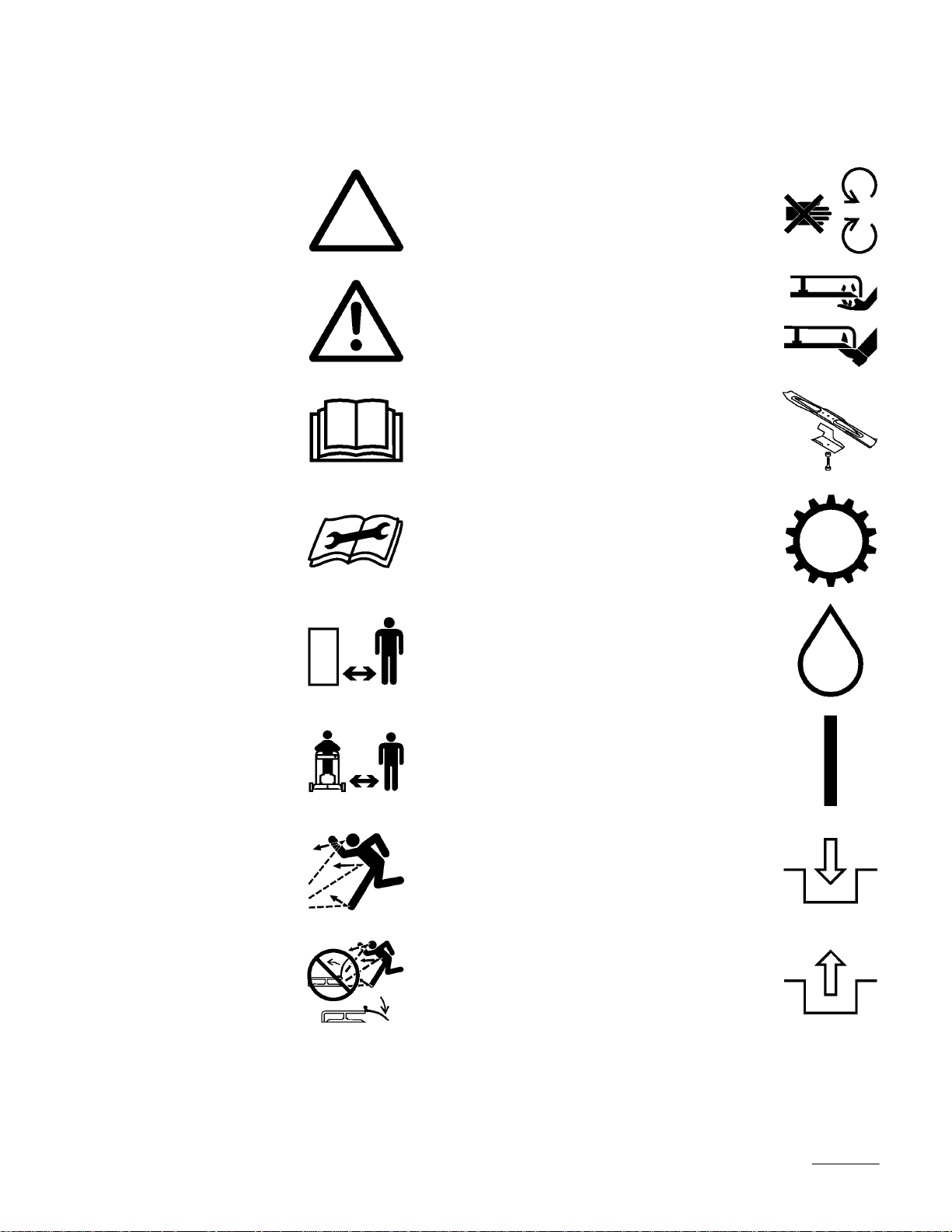
Symbol Glossary
Safety alert triangle —
symbol within triangle
indicates a hazard.
Safety alert symbol
Read operator’s
manual.
Consult technical
manual for proper
service procedures.
Do not open or
remove safety shields
while engine is
running.
Rotating blade can cut
off toes or fingers.
Stay clear of mower
blade as long as
engine is running.
To avoid blade failure
when mulching, use
blade stiffener when
mower is equipped
with mulching plug.
Transmission
Stay a safe distance
from the machine.
Stay a safe distance
from the mower.
Throw or flying
objects — Whole body
exposure
Thrown or flying
objects — Rotary
side-mounted mower.
Keep deflector shield
in place.
Oil
On/Run
Engage
Disengage
GB–5
Page 16

Stop engine before
leaving operator
position.
Battery charging
condition
Hourmeter/elapsed
operating hours
Fast Neutral
Slow First gear
Decreasing/Increasing Second gear
Grease lubrication
point
Fuel
Third gear
Engine start
Engine stop
Choke Pull rope.
Cutting element —
basic symbol
Cutting element —
height adjustment
GB–6
Page 17
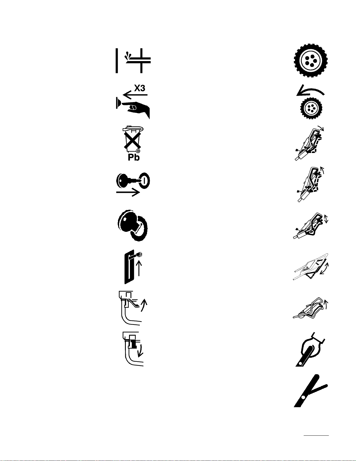
Primer (start aid) Wheel
Push primer three
times.
Properly dispose of
batteries.
Insert key in ignition
switch.
Turn key in ignition
switch.
Move control.
Wheel traction
Lower control bar.
Raise control bar.
Raise/lower control
bar.
Raise/lower control
bar.
Move control forward. Raise control bar.
Move control
rearward.
Raise control bar.
Lower control bar.
GB–7
Page 18

Assembly
Handle
1. Mount handle to outside of mower housing,
using bottom hole, with (2) 5/16–18 x 1–1/4” lg.
capscrews, washers, and thin nylon insert
locknuts (Fig. 2).
2. Secure handle latches to handle with (2) 5/16–18
x 1–1/2” lg. capscrews, washers and nylon insert
locknuts (Fig. 2).
Note: Handle height is adjustable for
operator comfort. Stand behind mower
handle to gauge height. To adjust
handle height, reposition capscrews
and locknuts securing handle latches to
handle into other mounting holes in
latches.
Discharge Tunnel Plug
1. Open the discharge door by pulling forward on
the handle and moving it rearwards (Fig. 6).
Hold the discharge door handle to prevent the
spring–loaded door from closing while inserting
the plug.
2. Since the plug is slightly wider than the
discharge tunnel opening, rotate the plug
clockwise slightly while inserting it (Fig. 6).
Make sure the arrow on the plug decal is
pointing upwards.
3. Push the plug all the way in until the spring clip
on the bottom of the plug clicks into place,
locking the plug securely into the discharge
tunnel (Fig. 6). Release discharge door handle to
lock top of plug.
Before Starting
3. Slide bag support rod thru top mounting holes in
handle and secure each end with a cap locknut
(Fig. 2).
4. Use a cable tie to secure the control cables to left
handle below the bag support rod.
5. Pull starter rope through rope guide on handle
(Fig. 5).
Gas Tank
1. Start self–tapping screws into bottom of gas tank
and then remove screws.
2. Hook plastic clips on front of gas tank into slots
on rear of engine (Fig. 3).
3. Secure gas tank to tank base with (2)
self–tapping screws (Fig. 3). Do not overtighten
screws.
4. Remove red cap from end of fuel line and from
end of elbow fitting on gas tank. Slide end of
fuel line onto elbow fitting (Fig. 4). Secure fuel
line in place with fuel line clamp.
Fill Crankcase With Oil
Fill crankcase with SAE 30 or 10W30 oil until oil
level reaches FULL mark on dipstick as shown in
(Fig. 8). The maximum crankcase capacity is 26
ounces (0.77 liters) of oil with the oil filter installed
and 22 ounces (0.65 liters) without the oil filter
installed. Use any high quality detergent oil having
the American Petroleum Institute (API) “service
classification” — SF, SG, SH or SJ.
Before each use, ensure oil level is between ADD and
FULL marks on dipstick (Fig. 8). Add oil if level is
low.
1. Position mower on level surface and clean
around oil dipstick.
2. Remove dipstick by rotating cap
counterclockwise 1/4 turn.
3. Wipe dipstick and insert it into filler neck.
Rotate cap clockwise 1/4 turn. Then remove
dipstick and check level of oil (Fig. 8). If level is
low, add only enough oil to raise level to FULL
mark on dipstick. DO NOT FILL ABOVE
FULL MARK BECAUSE ENGINE COULD
BE DAMAGED WHEN STARTED. POUR
OIL SLOWLY.
GB–8
Page 19

4. Insert dipstick into filler neck and rotate cap
clockwise 1/4 turn to lock.
Note: Check oil level each time mower is
used or after every 5 operating hours.
Initially, change oil after the first 5
hours of operation; thereafter, change
oil after every 50 hours of operation.
More frequent oil changes are required
in dusty or dirty conditions.
Fill Fuel Tank With Gasoline
POTENTIAL HAZARD
• In certain conditions gasoline is extremely
flammable and highly explosive.
WHAT CAN HAPPEN
• A fire or explosion from gasoline can burn
you, others, and cause property damage.
HOW TO AVOID THE HAZARD
• Use a funnel and fill the fuel tank outdoors,
in an open area, when the engine is cold.
Wipe up any gasoline that spills.
• Do not fill the fuel tank completely full.
Add gasoline to the fuel tank until the level
is 1/4” to 1/2” (6 mm to 13 mm) below the
bottom of the filler neck. This empty space
in the tank allows gasoline to expand.
• Never smoke when handling gasoline, and
stay away from an open flame or where
gasoline fumes may be ignited by a spark.
• Store gasoline in an approved container
and keep it out of the reach of children.
• Never buy more than a 30-day supply of
gasoline.
This engine is certified to operate on unleaded
gasoline. Toro strongly recommends the use of fresh,
clean, UNLEADED regular grade gasoline with an
octane rating of 85 or higher in Toro gasoline
powered products. Unleaded gasoline burns cleaner,
extends engine life, and promotes good starting by
reducing the build-up of combustion chamber
deposits. In countries other than U.S.A., leaded
gasoline may be used if it is commercially available
and unleaded is unavailable.
IMPORTANT: Do not mix oil with the gasoline.
Do not use gasoline that has been stored in an
approved container from one season to the next.
Toro also recommends that Toro
Stabilizer/Conditioner be used regularly in all Toro
gasoline powered products during operation and
storage seasons. Toro Stabilizer/Conditioner cleans
the engine during operation and prevents gum–like
varnish deposits from forming in the engine during
periods of storage.
IMPORTANT: Some fuels, called oxygenated or
reformulated gasolines, are gasolines blended with
alcohols or ethers. Excessive amounts of these
blends can damage the fuel system or cause
performance problems. Never use methanol
gasoline containing methanol, gasohol containing
more than 10% ethanol or white gas because
engine fuel system damage could result. If any
undesirable operating symptoms occur, use
gasoline with a lower percentage of alcohol or
ether.
Do not use fuel additives other than those
manufactured for fuel stabilization during storage
such as Toro’s Stabilizer/Conditioner or a similar
product. Toro’s Stabilizer/Conditioner is a
petroleum distillate based conditioner/stabilizer.
Toro does not recommend stabilizers with an
alcohol base such as ethanol, methanol or
isopropyl. Additives should not be used to try to
enhance the power or performance of machine.
1. Clean around fuel tank cap and remove cap from
tank. Using unleaded gasoline, add fuel to 1/4”
to 1/2” (6 to 13 mm) from top of tank, not into
the filler neck. Do not fill the tank full.
2. Reinstall fuel tank cap and wipe up any spilled
gasoline.
3. Connect spark plug wire (if disconnected)
(Fig. 12).
,
GB–9
Page 20

Recycling Tips
General Tips
!/3 of the grass blade should be cut off. Cutting
below the 1-#/4” setting is not recommended
unless grass is sparse or it is late fall when grass
growth begins to slow down.
Follow these instructions whether cutting grass or
leaves for the best cutting results and lawn
appearance:
• Maintain a sharp blade
season. Periodically file down nicks on blade.
• Only mow dry grass or leaves. Wet grass and
leaves tend to clump on yard and may cause
mower to plug or engine to stall. They also may
be slippery to walk on and could cause you to
slip and fall.
POTENTIAL HAZARD
throughout the cutting
• Wet grass or leaves can cause you to slip
and contact blade.
WHAT CAN HAPPEN
• Blade contact can seriously injure you.
HOW TO AVOID THE HAZARD
• Mow only in dry conditions.
• Set engine speed to fastest position. Maximum
horsepower provides best cutting results.
• When cutting grass over six inches tall, you may
want to first mow using the highest height-of-cut
setting and a slower walking speed; then mow
again at a lower setting for best lawn appearance.
If grass is too long and leaves clumps on top of
lawn, mower may plug and cause engine to stall.
• Alternate mowing direction. This helps disperse
clippings over lawn for even fertilization.
If the finished cut lawn appearance is unsatisfactory,
try one or more of the following:
• Sharpen the blade.
• Walk at a slower pace while mowing.
• Raise the height-of-cut setting on your mower.
• Cut grass more frequently.
• Overlap cutting swaths instead of cutting a full
swath with each pass.
• Mow across the marginal areas a second time.
• Set height-of-cut on front wheels one notch
lower than rear wheels. (example: set front
wheels at 1-#/4” setting and rear wheels at 2-!/4”
setting)
• Clean clippings or leaves from underside of
mower deck after each mowing.
• Keep engine in good running condition. Cutting
and recutting requires more horsepower.
• Clean air filter more frequently. Cutting and
recutting stirs up more clippings and dust which
clogs the air filter and reduces engine
performance.
Cutting Grass
• Grass grows at different rates at different times
of the year. In the heat of the summer, it is
generally best to cut grass at the 1-#/4”, 2-!/4” or
2-#/4” height-of-cut settings (Fig. 9). Only about
GB–10
Cutting Leaves
• When cutting is complete, always be sure that
50% of the lawn shows through the cut leaf
cover. This may require one or more passes over
the leaves.
• For light leaf coverage, position all wheels at the
same height-of-cut setting.
• If there are more than five inches of leaves on
lawn, set the front wheels one or two notches
higher than the rear wheels. This makes it easier
to feed leaves under mower deck.
• Walk at a slower mowing speed if leaves are not
being cut up finely enough to be hidden down in
the grass.
Page 21

• If you cut up a lot of oak leaves, you might want
to add lime to your grass in the spring. Lime
reduces the acidity of oak leaves.
Operation
Operating Tips
1. CHECK OIL LEVEL—Maintain oil level
between ADD and FULL marks as shown on
dipstick (Fig. 8).
2. BEFORE EACH MOWING—Be sure blade
brake, self–propelled drive, and control bar
function properly. When control bar is released,
blade and self–propelled drive are designed to
stop. If controls are not functioning properly, do
not use mower until controls are repaired.
3. SHARP BLADE—Begin each cutting season
with a sharp blade. Periodically file down nicks.
Controls
Throttle control, blade/self–propelled control bar and
fingertip starter are on upper handle (Fig. 10). Ground
speed control is located at rear of belt cover (Fig. 11).
Note: Do not use primer to restart a warm
engine after a short shutdown.
However, cool weather may require
priming to be repeated.
5. Pull recoil starter out until positive engagement
results; then pull vigorously to start the engine.
Allow the engine to warm-up. During warm-up,
the equipment can be operated. Regulate throttle
as desired when engine starts. Move ground
speed control to desired setting.
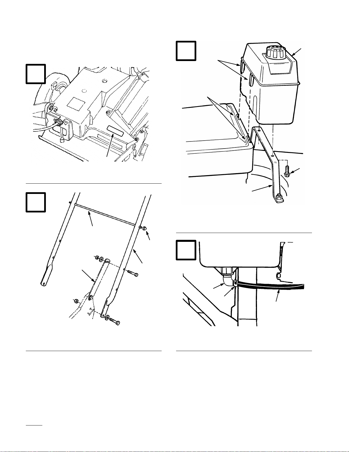
6. BLADE AND TRACTION OPERATION
(Fig. 13)—When control bar is in position “A”,
slide control bar to right and raise to position
“B” to engage blade. Squeeze control bar against
handle to position “C” to drive. To disengage
traction drive but keep blade engaged, gradually
release control bar to position “B”. To
self–propel with blade disengaged, simply
squeeze control bar against handle to position
“C”, without sliding control bar to right.
7. STOPPING—To stop engine, release control bar
and move throttle control to
off spark plug if mower will be unattended or
not used.
(OFF). Pull wire
Using Discharge Tunnel Plug
Starting, Stopping, And
Self–propelling
Note: The engine requires a warm-up period
of one minute to several minutes,
depending on the temperature.
1. Push spark plug wire onto spark plug (Fig. 12).
2. Move throttle control to
3. Move ground speed control to
4. Push primer three (3) times (Fig. 12). Wait
about two (2) seconds between each push.
(FAST) position.
(NEUTRAL).
1. Make sure engine is off. Open the discharge door
by pulling forward on the handle and moving it
rearwards (Fig. 6). Hold the discharge door
handle to prevent the spring–loaded door from
closing while inserting the plug.
2. Since the plug is slightly wider than the
discharge tunnel opening, you must rotate the
plug clockwise slightly while inserting it
(Fig. 6). Make sure the arrow on the plug decal
is pointing upwards.
3. Push the plug all the way in until the spring clip
on the bottom of the plug clicks into place,
locking the plug securely into the discharge
tunnel (Fig. 7). Release the discharge door
handle to lock the top of the plug.
GB–11
Page 22

4. To remove the plug, move the discharge door
handle rearwards while at the same time lift up
the spring clip on the bottom of the plug. When
the plug is unlocked, pull it out of the discharge
tunnel.
Note: When grass is thick and lush, clippings
may collect on and around the
discharge tunnel plug. This may make
plug removal difficult. Clean plug
thoroughly after each use. Refer to
Cleaning Mower, page 17.
Using Grass Bag
Occasionally you may wish to use the grass bag for
bagging extra long grass, lush grass or leaves.
1. Stop engine and wait for all moving parts to
stop.
4. Pull discharge door handle forward until pin
clears catch and move handle rearward until pin
locks in bag notch (Fig. 15). Discharge door in
mower housing is now open.
POTENTIAL HAZARD
• A worn grass bag could allow small stones
and other similar debris to be thrown in
operator’s or bystander’s direction.
WHAT CAN HAPPEN
• Thrown objects can cause serious personal
injury or death to operator or bystanders.
HOW TO AVOID THE HAZARD
• Check the grass bag frequently. If it is
damaged, install a new genuine TORO
replacement bag.
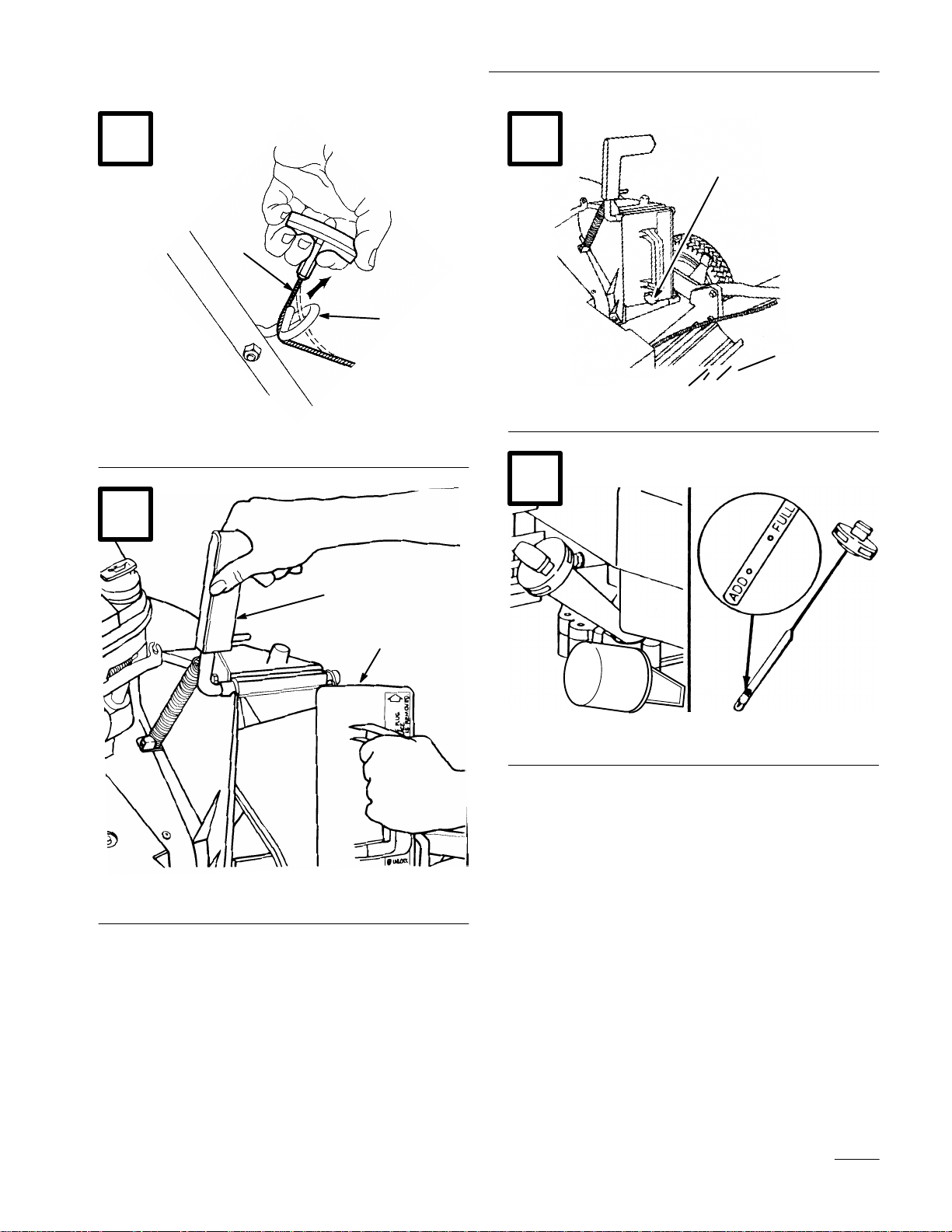
2. Ensure discharge door handle is fully forward
and pin is engaged in catch (Fig. 14).
3. INSTALLING BAG—Slide hole in bag frame
onto retaining post on discharge tunnel (Fig. 14).
Set rear of bag frame onto lower handle.
POTENTIAL HAZARD
• Grass clippings and other objects can be
thrown from an open discharge tunnel.
WHAT CAN HAPPEN
• Objects thrown with enough force could
cause serious personal injury or death to
operator or bystander.
HOW TO AVOID THE HAZARD
• Never open door on discharge tunnel when
engine is running unless the grass bag,
optional side discharge attachment or
discharge tunnel plug is securely installed.
POTENTIAL HAZARD
• Thrown objects may result if discharge
door does not close completely.
WHAT CAN HAPPEN
• Thrown objects can cause serious
personal injury or death.
HOW TO AVOID THE HAZARD
• If discharge door cannot be closed because
grass clippings clog discharge area, stop
engine and gently move discharge door
handle back and forth until door can be
closed completely. If door still cannot be
closed, remove obstruction with a stick, not
your hand.
5. EMPTYING BAG—Stop engine and wait for all
moving parts to stop. Raise discharge door
handle and move it forward to engage the
locking pin with the catch (Fig. 14). Grasp
handles at front and rear of bag and lift bag off
mower. Gradually tip bag forward to empty
clippings.
GB–12
Page 23

6. To reinstall bag, repeat steps 3-4.
Adjusting Height-of-cut
The height-of-cut is adjustable from approximately
#/4 to 3-!/4 inches (19 mm to 83 mm), in !/2 inch
(12.7 mm) increments (Fig. 9). Moving height-of-cut
adjuster forward raises height-of-cut.
1. Stop the engine and wait for all moving parts to
stop. Pull wire off spark plug (Fig. 12).
Maintenance
POTENTIAL HAZARD
• When wire is on spark plug, someone could
accidentally start the engine.
WHAT CAN HAPPEN
• Accidental starting of engine could
seriously injure you or other bystanders.
HOW TO AVOID THE HAZARD
• Pull wire off spark plug before you do any
maintenance. Also push wire aside so it
does not accidentally contact spark plug.
Servicing Air Cleaner
2. For easier adjustment, lift housing up so wheel is
off ground. Do not place hands under deck to
lift housing. Squeeze adjusting lever toward
wheel (Fig. 16) and move it to the desired
setting. Assure pin on adjusting lever engages
notch in mower housing wear plate. Adjust all
wheels to the same setting.
POTENTIAL HAZARD
• Adjusting height-of-cut levers could bring
hands into contact with moving blade.
WHAT CAN HAPPEN
• Contact with blade could cause serious
personal injury.
HOW TO AVOID THE HAZARD
• Stop engine and wait for all moving parts
to stop before changing height-of-cut.
• Do not put fingers under housing to lift
mower when adjusting height-of-cut levers.
Normally, clean air cleaner pre-cleaner after every 25
operating hours or every season. Clean the paper
cartridge after every 100 hours or every season. More
frequent cleaning is required when mower is operated
in dusty or dirty conditions. Replace air cleaner parts,
if very dirty.
IMPORTANT: Do not operate engine without
air filter elements; extreme engine wear or
damage will occur.
Note: Tipping mower on wrong side to
service underside of mower may cause
damage to air filters.
1. Stop engine and pull wire off spark plug
(Fig. 12).
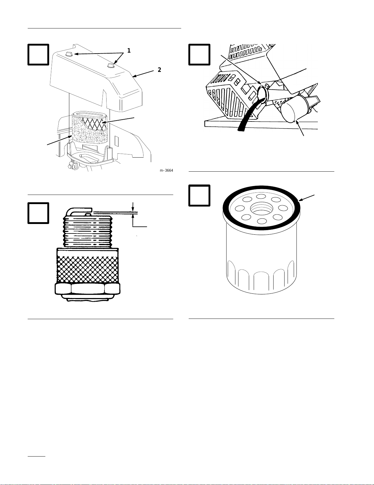
2. Remove two (2) knobs securing air cleaner cover
to engine (Fig. 17).
3. Lift cover off. Clean cover thoroughly.
4. Carefully remove pre-cleaner. If pre-cleaner is
dirty, carefully wash it in a solution of liquid
soap and warm water. Rinse in clear water.
Allow to dry thoroughly before using.
5. If paper cartridge is dirty, clean the paper filter
by tapping it gently on a flat surface. If very
dirty, replace cartridge.
GB–13
Page 24

IMPORTANT: Do not oil pre–cleaner or
paper cartridge. Do not use pressurized air to
clean paper cartridge.
6. Reinstall pre-cleaner over paper cartridge.
Reinstall air cleaner cover and tighten securely
in place with two (2) knobs.
Changing Crankcase Oil
Change oil after the first 5 operating hours and then
after every 50 hours or every season. Change oil
while engine is warm.
Note: Change oil every 25 hours when
operating under heavy load or in high
temperatures.
Replacing Spark Plug
Remove plug after every 25 operating hours and
check its condition. Replace spark plug every 100
operating hours or every season. Use a Champion
RC12YC spark plug or equivalent.
1. Stop engine and wait for all moving parts to
stop. Pull wire off spark plug (Fig. 12).
2. Clean around spark plug and remove plug from
cylinder head.
IMPORTANT: Replace a cracked, fouled, or
dirty spark plug. Do not sand blast, scrape, or
clean electrodes because engine damage could
result from grit entering cylinder.
3. Set air gap at 0.020” (0.5 mm) (Fig. 18). Install
correctly gapped spark plug and gasket seal.
Tighten plug firmly to 14 ft–lb (19 Nm).
1. Stop engine and wait for all moving parts to
stop. Pull wire off spark plug (Fig. 12).
2. Remove grass bag. Drain gasoline from fuel
tank: refer to Draining Gasoline, page 14.
3. Remove dipstick from oil fill tube and place a
drain pan next to left side of mower.
4. Tip mower on its left side, allowing oil to drain
into drain pan (Fig. 19).
5. When oil is drained, return mower to upright
position and add fresh oil to engine. Refer to Fill
Crankcase With Oil, page 8.
Replacing Oil Filter
Replace the oil filter (Fig. 19) after every 100
operating hours or yearly, whichever occurs first.
1. Drain gasoline from fuel tank; refer to Draining
Gasoline, page 14.
Draining Gasoline
1. Stop engine and wait for engine to cool. Pull
wire off spark plug (Fig. 12).
Note: Drain gasoline from a cold engine
only.
2. Remove cap from fuel tank and use pump–type
syphon to drain fuel into clean gas can.
Note: This is the only procedure
recommended for draining fuel.
GB–14
2. Drain oil. Refer to Changing Crankcase Oil,
page 14.
3. Place a rag under oil filter to catch any oil that
may leak out as filter is removed.
4. Remove oil filter and discard it.
5. Using your finger, coat the gasket on the new
filter with oil (Fig. 20).
6. Install the new filter and hand tighten it 2/3 turn
only.
7. Check the filter for any oil leaks.
8. Properly discard the oily rag.
Page 25

Adjusting Throttle
Throttle control adjustment may be required if engine
does not start. Whenever a new throttle control cable
is installed, throttle must be adjusted.
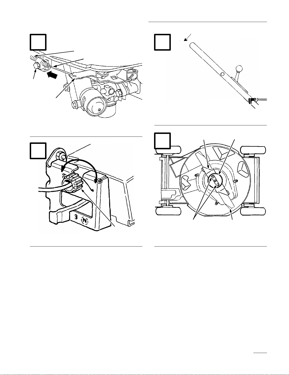
3. CHECK ADJUSTMENT—Slowly pull mower
backward while control bar is gradually moved
toward handle. Adjustment is correct when rear
wheels stop turning and control bar is about 1
inch from handle (Fig. 23).
1. Stop engine and wait for all moving parts to
stop. Pull wire off spark plug (Fig. 12).
2. Loosen cable clamp screw until throttle cable
slides (Fig. 21).
3. Move governor control lever, throttle cable and
casing in direction of arrow as far as possible
(Fig. 21).
4. Move throttle control to
5. Tighten cable clamp screw to lock adjustment in
place.
(FAST position).
Cleaning Cooling System
After every 100 operating hours, clean dirt and chaff
from cylinder, cylinder head fins and from around
carburetor and linkage. Also remove debris from air
intake slots on recoil housing. This will ensure proper
cooling and optimum engine performance.
Adjusting Wheel Drive
Inspecting/Removing/
Sharpening Blade
Always mow with a sharp blade. A sharp blade cuts
cleanly and without tearing or shredding the grass
blades like a dull blade.
1. Stop engine and wait for all moving parts to
stop. Pull wire off spark plug (Fig. 12).
2. Drain gasoline from fuel tank; refer to Draining
Gasoline, page 14.
3. Tip mower on its left side (Fig. 24).
POTENTIAL HAZARD
• Someone could accidentally start the
engine.
WHAT CAN HAPPEN
• Accidental starting of engine could cause
serious injury to operator or bystanders.
HOW TO AVOID THE HAZARD
• Do not attempt to inspect, remove or
replace blade without first removing the
spark plug wire from spark plug and
fastening it away from accidental contact
with spark plug.
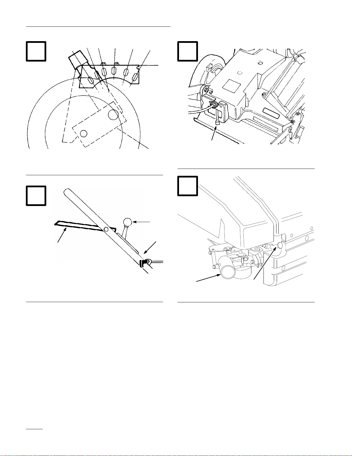
If mower does not self–propel or self–propels when
control bar is more than 1–1/2 inches from the
handle, adjust wheel drive control knob on rear of
gear box.
1. Close door in mower housing and remove grass
bag.
2. ADJUSTMENT (Fig. 22)—Rotate control knob
clockwise 1/2 turn if mower does not
self–propel. If mower creeps forward, rotate
knob 1/2 turn counterclockwise to loosen belt.
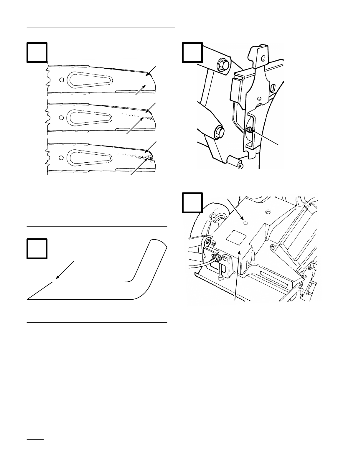
4. INSPECTING BLADE—Carefully examine
blade for sharpness and wear, especially where
flat and curved parts meet (Fig. 25A). Since sand
and abrasive material can wear away the metal
that connects the flat and curved parts of the
blade, check blade before using the mower. If a
slot or wear is noticed, (Fig. 25B & C), replace
blade. Refer to step 5.
Note: For best performance, install new blade
before cutting season begins. During
the year, file down small nicks to
maintain the cutting edge.
GB–15
Page 26

POTENTIAL HAZARD
• A worn or damaged blade could break and
a piece of blade could be thrown into
operator’s or bystander’s area.
POTENTIAL HAZARD
• Operating mower without accelerator in
place could cause blade to flex, bend or
break.
WHAT CAN HAPPEN
• A thrown piece of blade could cause serious
personal injury or death to operator or
bystanders.
HOW TO AVOID THE HAZARD
• Inspect blade periodically for wear or
damage.
• Replace a worn or damaged blade.
5. REMOVING BLADE—Grasp end of blade
using a rag or thickly padded glove. Remove
blade nuts, anti–scalp cup, accelerator, and blade
(Fig. 24).
6. SHARPENING BLADE—Using a file, sharpen
top side of blade and maintain original cutting
angle (Fig. 26). The blade will remain balanced
if same amount of material is removed from both
cutting edges.
WHAT CAN HAPPEN
• A broken blade could cause serious injury
or death to operator or bystanders.
HOW TO AVOID THE HAZARD
• Do not operate mower without accelerator.
Lubrication
After every 25 operating hours or when season ends,
pivot arms must be lubricated.
1. Move rear wheel height–of–cut levers to center
setting. Wipe grease fittings with clean rag
(Fig. 27). Install grease gun onto fitting and
gently apply 2 or 3 pumps of #2 Multi–Purpose
Lithium Base Grease. Excessive grease pressure
may damage seals.
Lubricating Gear Case
After every 100 operating hours, grease the gear case
with #2 Multi–Purpose Lithium Base Grease.
IMPORTANT: Check balance of blade by
putting it on a blade balancer. An inexpensive
balancer can be purchased at a hardware
store. A balanced blade stays in a horizontal
position and an unbalanced blade settles to
the heavy side. If blade is not balanced, file
more metal off cutting edge on heavy end of
blade.
7. Reinstall sharp, balanced blade, blade
accelerator, anti–scalp cup, and blade nuts. Sail
part of blade must point toward top of mower
housing to assure correct installation. Tighten
blade nuts to 15–27 ft–lbs (20–37 Nm).
GB–16
1. Remove bag.
2. Install grease gun onto fitting thru belt cover
opening (Fig. 28). Gently apply 1–2 pumps of
grease.
3. Reinstall bag.
Adjusting Blade Brake Cable
Whenever a new blade brake cable assembly is
installed or the blade brake belt is replaced, the blade
brake cable should be adjusted.
1. Stop engine and wait for all moving parts to
stop. Pull wire off spark plug (Fig. 12).
Page 27

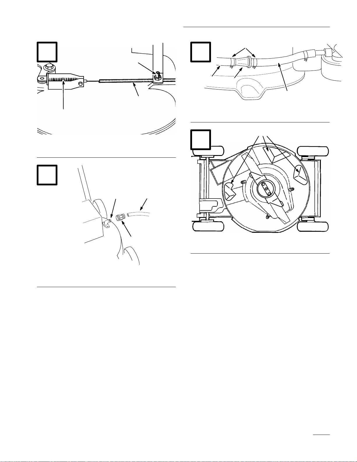
2. Loosen cable clamp screw until brake cable
conduit slides (Fig. 29). Pull cable to remove
slack, but do not put tension on spring. Tighten
screw to lock adjustment in place.
POTENTIAL HAZARD
• Do not over–tighten blade brake cable.
Over–tightening could cause blade brake to
be pulled off brake drum. If brake does not
contact drum, blade will not stop rotating
when control bar is released.
WHAT CAN HAPPEN
• A rotating blade could cause serious
personal injury.
HOW TO AVOID THE HAZARD
• Check the blade brake mechanism each
time brake cable is adjusted to ensure
brake is stopping blade in 3 seconds or less.
• If blade does not stop rotating in 3 seconds
or less, bring unit to your local Authorized
Toro Service Dealer for inspection and
repair.
POTENTIAL HAZARD
• Grass clippings and other objects can be
thrown from an open discharge tunnel.
WHAT CAN HAPPEN
• Thrown objects can cause serious injury or
kill operator or bystanders.
HOW TO AVOID THE HAZARD
• Never start or operate the mower unless
one of the following is true:
1. The discharge tunnel plug is locked
securely in discharge tunnel.
2. The grass bag is locked in place.
3. The optional side discharge chute is
locked in place.
4. The discharge tunnel door is locked
in place.
Underside of Mower Housing
Keep underside of mower housing clean. Be
especially careful to keep kickers free of debris
(Fig. 32).
Cleaning Mower
Plug
To ensure best performance, the discharge tunnel plug
must be cleaned after each use. When grass is thick
and lush, clippings may collect on and around the
plug; this may make plug removal difficult. After
each use, remove plug from discharge tunnel and
clean off all debris.
Discharge Tunnel
Always be sure that discharge tunnel door closes
securely when handle is released. If debris prevents
discharge door from closing securely, clean inside of
discharge tunnel and door thoroughly.
Washing Method
1. Position mower on a flat surface near a garden
hose.
2. Attach a quick disconnect coupling (sold
separately) to the end of the garden hose. Attach
coupling to mower washout fitting and turn
water on high (Fig. 30).
3. Start the engine.
4. Let mower run for two minutes.
5. Stop the engine.
6. Turn the water off and remove coupling from the
washout fitting.
7. Restart mower and let it run for one minute to
dry out moisture on the mower and its
components.
GB–17
Page 28

8. If underside of mower deck has excessive grass
build-up or packing, reconnect the hose to the
washout fitting, turn the water on high and run
the mower for two minutes. Stop the mower and
turn off the water. Let the mower soak for 30
minutes. Then turn the water on high again and
run the mower for another two minutes.
1. Stop engine and wait for all moving parts to
stop. Pull wire off spark plug (Fig. 12).
2. Drain gasoline from fuel tank; refer to Draining
Gasoline, page 14.
3. Tip mower on its left side.
Scraping Method
If washing does not remove all debris from under
deck, tip mower and scrape it clean.
1. Pull wire off spark plug (Fig. 12).
2. Drain gasoline from fuel tank: refer to Draining
Gasoline, page 14.
3. Tip mower on its left side (Fig. 32).
4. Remove dirt and grass clippings with a
hardwood scraper. Avoid burrs and sharp edges.
5. Turn mower upright.
6. Refill gas tank.
7. Reconnect spark plug wire.
Belt Cover
Keep area under belt cover free of debris.
1. Remove bolts securing belt cover (Fig. 28) to
mower housing. Lift off cover and brush out all
debris from belt area. Reinstall belt cover.
4. Remove (2) blade nuts, anti–scalp cup,
accelerator, and blade (Fig. 24).
5. Loosen tabs securing BBC shield to deck by
loosening nuts or bolts on tabs (Fig. 33). Rotate
tabs 180_ to move them out of the way.
6. Remove BBC shield and brush or blow all debris
from under shield and around BBC system.
7. Reinstall BBC shield. Rotate tabs 180_ back into
position. Tighten nuts or bolts on tabs to secure
BBC shield to deck.
8. Reinstall blade, accelerator, anti–scalp cup, and
(2) blade nuts.
9. Turn mower upright.
10. Reinstall spark plug wire on spark plug.
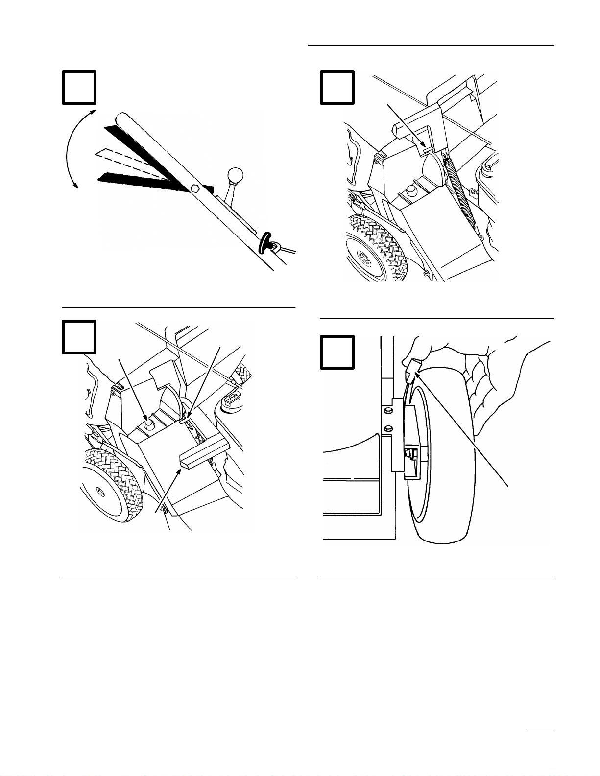
Servicing Wheels (Fig. 34)
Removal
1. Stop engine and wait for all moving parts to
stop. Pull wire off spark plug (Fig. 12).
2. Remove capscrew, wheel spacer, and locknut
mounting wheel to pivot arm.
Cleaning Blade Brake Clutch
Shield
The BBC (Blade Brake Clutch) shield should be
cleaned periodically during the mowing season and at
the end of each mowing season to ensure best
performance and to prevents parts degradation. It is
convenient to clean the BBC shield at the same time
the blade is being sharpened because the blade needs
to be removed in order to remove the BBC shield.
GB–18
3. Separate wheel halves from tire by removing (4)
capscrews and locknuts.
Note: If bearings are to be removed from
bearing/hub assembly, remove by
pressing on bearing spacer.
Assembly
1. Position tire onto (1) wheel half, aligning lugs
on each.
Page 29

2. Place bearing/hub assembly into center hole of
wheel half. Make sure legs of hub are positioned
over flange of hole.
3. Place other wheel half onto bearing/hub
assembly aligning wheel and tire lugs and
mounting holes.
4. Using (2) 1/4—20 x 1.50” lg. fully threaded
screws or bolts and non–locking nuts, loosely
secure wheel halves together. Mount screws or
bolts in opposing holes.
Storage
1. For long term storage, either drain gasoline from
fuel tank or add a fuel stabilizer to the gasoline.
To drain gasoline, refer to Draining Gasoline,
page 14. After fuel is drained, start engine and
let it idle until all fuel is consumed and engine
stops. Repeat the starting procedure two more
times to ensure all gas is removed from the
engine. If gasoline is not drained, gum–like
varnish deposits will form and cause poor engine
operation, even starting problems.
5. Check alignment of all parts and tighten screws,
alternating from side to side for a uniform fit,
until wheel halves are drawn together.
6. Install (2) capscrews and locknuts, previously
removed, in remaining holes in wheel halves and
tighten. Remove (2) long screws or bolts and
replace with (2) capscrews and locknuts.
7. Reinstall wheel to pivot arm with capscrews,
spacer, and locknut. Make sure spacer is
positioned between wheel hub and pivot arm.
Fuel Filter
Replacing the Fuel Filter
Replace the fuel filter after every 100 operating hours
or yearly, whichever occurs first. The best time to
replace the fuel filter (Fig. 31) is when the fuel tank is
empty. Never install a dirty filter if it is removed from
the fuel line.
1. Squeeze the ends of the hose clamps together
and slide them away from the filter (Fig. 31).
Note: If engine is operating on oxygenated or
reformulated gasoline (gasoline
blended with an alcohol or an ether),
remove all fuel from tank and run
engine until it stops from lack of fuel
before storing.
Fuel can be left in gas tank only if a fuel
additive, such as Toro’s Stabilizer/Conditioner, is
added to gasoline and run through engine before
storing. Toro’s Stabilizer/Conditioner is a
petroleum distillate based conditioner/stabilizer.
Toro does not recommend stabilizers with an
alcohol base, such as ethanol, methanol or
isopropyl. Use fuel additive in recommended
quantities as specified on container.
Under normal conditions, fuel additives remain
effective in fuel for 6–8 months.
2. Drain oil: refer to Changing Crankcase Oil,
page 14. After oil is drained, do not fill
crankcase with oil until the following steps
(3–11) are completed.
3. Remove spark plug and pour 2 tablespoons of
SAE 30 oil into hole in cylinder. Pull starter rope
slowly to coat inside of cylinder. Install spark
plug and tighten to 14 ft–lb (19 Nm). DO NOT
REINSTALL WIRE ON SPARK PLUG.
2. Remove the filter from the fuel lines.
3. Install a new filter and move the hose clamps
close to the filter.
4. Clean mower housing: refer to Cleaning Mower,
page 17.
5. Clean BBC shield: refer to Cleaning Blade
Brake Clutch Shield, page 18.
GB–19
Page 30

6. Clean dirt and chaff from cylinder, cylinder head
fins, and blower housing. Also remove grass
clippings, dirt, and grime from external parts of
the engine, shrouding, and top of mower
housing.
13. Store mower in a clean, dry place, out of the
reach of children. Cover mower to keep it clean
and protected.
7. Check condition of blade: refer to
Inspecting/Removing/Sharpening Blade,
page 15.
8. Tighten all nuts, bolts, and screws.
9. Clean air cleaner: refer to Servicing Air Cleaner,
page 13.
10. Lubricate the pivot arms: refer to Lubrication,
page 16.
11. Touch up all rusted or chipped paint surfaces.
Toro Re–Kote paint is available from an
Authorized TORO Service Dealer.
12. Fill crankcase with oil: refer to Fill Crankcase
With Oil, page 8.
Accessories
For special conditions, the following accessories may
be purchased at your local Authorized Toro Service
Dealer.
1. Side Discharge Kit, Model No. 59113—Installs
in seconds. Rear mounted in place of the grass
bag or discharge tunnel plug. Disperses clippings
while trimming on both sides (Fig. 35).
2. Spark Arrestor and Screw (Part No.
94–1681)—If a spark arrestor is required
because of local, state, or federal regulations, it
may be purchased at your local Authorized
TORO Service Dealer. Clean screen after every
75 hours of operation. If mower is operated on
any California forest, brush, or grass covered
land without a properly operating spark arrestor,
the operator is violating state law, Section 4442
Public Resources Code.
GB–20
 Loading...