

Page 1

ONAN E125 V, E140V ENGINE SERVICE MANUAL
Table of Contents – Page 1 of 3
SAFETY PRECAUT I O NS
GENERAL
BATTERIES
PROTECT AGAINST MOVING PARTS
FUEL SYSTEM
EXHAUST SYSTEM
EXHAUST GAS IS DEADLY
KEEP THE UNIT AND SURROUNDING AREA CLEAN
SUPPLEMENT 965-1053
PURPOSE
SERVICE MANUAL 965-0764 REVISIONS
CARBURETOR (BEGINNING SPEC E)
SECTION 1. GENERAL INFORMATION
SECTION 2. SPECIFICATIONS
SECTION 3. DIMENSIONS AND CLEARANCES
SECTION 4. ASSEMBLY TORQUES
SECTION 5. ENGINE TROUBLESHOOTING
SECTION 6. MAINTENANCE
PERIODIC MAINTENANCE SCHEDULE
ENGINE INSPEC TION
AIR CLEANER AND ELEMENT WRAPPER
OIL CHANGE
OIL FILTER CHANGE
COOLING
VALVE CLEARANCE
SPARK PLUG
SECTION 7. LUBRICATION
OIL CHANGE
OIL FILTER CHANGE
OIL LEVEL CHECK
OIL PRESSURE
OIL PRESSURE RELIEF VALVE
OIL PUMP
DISASSEMBLY
ROTOR LOBE CLEARANCE
OUTER ROTOR AND PUMP BODY CLEARANCE
ROTOR AND COVER CLEARANCE
ASSEMBLY
SECTION 8. ELECTRICAL
IGNITION SYSTEM
SPARK PLUG
IGNITION COIL
IGNITION TIMING
FLYWHEEL ALTERNATORS
ALTERNATOR OUTPUT TESTS
Page 2

ONAN E125 V, E140V ENGINE SERVICE MANUAL
Table of Contents – Page 2 of 3
SECTION 9. FUEL
GASOLINE CARBURETOR
DISASSEMBLY
INSPECTION/SERVICE
ASSEMBLY
CO ADJUSTMENT
IMPULSE FUEL PUMP
INSPECTION/SERVICE
FUEL PUMP REMOVAL
FUEL PUMP INSTALLATION
LPG FUEL SYSTEM
GOVERNOR ADJUSTMENTS
1. GOVERNOR LEVER ADJUSTMENT
2. IDLE SPEED ADJUSTMENTS
3. CHOKE ADJUSTMENT
4. SPEED CONTROL CABLE ADJUSTMENT
AIR CLEANER
FOAM WRAPPER ELEMENT
PAPER ELEMENT
SECTION 10. STARTING
RECOIL STARTER
110 VAC STARTER
SOLENOID SHIFT START ER
SOLENOID
ARMATURE
COMMUTATOR AND MICA
STARTER BODY
BRUSHES
OVERRUNNING CLUTCH
SECTION 11. ENGINE BLOCK ASSEMBLY
INTRODUCTION
ENGINE DISASSEMBLY/ASSEMBLY
SUGGESTED DISASSEMBLY ORDER
SUGGESTED ASSEMBLY PROCEDURE
OPERATION
COMPRESSION TEST
FLYWHEEL
DISASSEMBLY
SERVICE/INSPECTION
ASSEMBLY
VALVE COVER
ROCKER ARM
DISASSEMBLY
INSPECTION/SERVICE
ASSEMBLY
CYLINDER HEAD
DISASSEMBLY
ASSEMBLY
Page 3

ONAN E125 V, E140V ENGINE SERVICE MANUAL
Table of Contents – Page 3 of 3
SECTION 11. ENGINE BLOCK ASSEMBLY –CON’T
VALVE SYSTEM
TAPPETS
DISASSEMBLY
INSPECTION/SERVICE
VALVE STEM AND VALVE GUID E C LE AR ANC E:
VALVE GUIDE REPLACEMENT:
ASSEMBLY
VALVE SPRING:
VALVE FACE AND SEAT GRINDING
INSPECTION/SERVICE
VALVE SEAT WIDT H:
VALVE SEAT CUTTING:
VALVE CLEARANCE:
OIL BASE
DISASSEMBLY
ASSEMBLY
GOVERNOR
BALANCING SHAFTS
DISASSEMBLY
OIL BASE BEARING TO SHAFT CLEARANCE:
ASSEMBLY
CRANKSHAFT AND CAMSHAFT
DISASSEMBLY
INSPECTION/SERVICE
CRANKSHAFT JOURNAL:
CAMSHAFT LOBE HEIGHT:
OIL BASE BEARING TO CAMSHAFT CLEARANCE:
ASSEMBLY
COMPRESSION RELEASE SYSTEM
PISTON, PISTON PIN, RINGS, CONNECTING ROD
DISASSEMBLY
PISTON INSPECTION
PISTON INSPECTION:
PISTON PIN HOLE INSIDE DIAMETER:
PISTON PIN OUTSIDE DIAMETER:
PISTON RING AND RING GROOVE CLEARANCE:
CONNECTING ROD SMALL END INSIDE DIAMETER:
CONNECTING ROD TO CRANKSHAFT JOURNAL OIL CLEARANCE:
CONNECTING ROD SIDE CLEARANCE:
ASSEMBLY
CYLINDER BLOCK
CLEANING
INSPECTION
REBORING THE CYLINDER
HONING CYLINDER (USING PRECISION HONES)
DEGLAZING CYLINDER BORE
BALL BEARINGS
OIL SEAL
Page 4
El25V,
El40V
Elite
Series
Printed
in
U.S.A.
965-0764
Spec
A-C
6-94
Page 5
Safety
Before
operating the engine,
become familiar with it and the equipment.
operatlon can be achieved only
Precautions
read the Operator's Manual and
Safe and efficient
If
the equipment
Is
properly operated and maintained.
The following symbols, found throughout this manual, alert you
to potentially dangerous conditions to the operator, service per-
the
sonnel, or
equipment.
Thls
symbol
warns of immediate hazards
whlch will result in severe personal Injury or death.
WARNING
This symbol refers to a hazard or unsafe
practice whlch can result in severe personal Injury or
death.
CAUTION)
This symbol refers to a hazard
or
unsafe
practlce whlch can result In personal Injury or product or
property damage.
Fuels, electrical equipment, batteries, exhaust gases and
moving parts present potential hazards that can result in severe
personal injury. Take care in following these recommended
procedures.
consulted and complied with.
WARNING
use
In any type of aircraft.
All
local, state and federal codes should be
Thls engine is not designed or Intended for
Use
of this engine In aircraft can
result In engine failure and cause severe personal injury or
death.
GENERAL
Provide appropriate fire extinguishers and install them in
convenient locations. Use an extinguisher rated ABC by
NFPA.
Make sure that all fasteners on the engine are secure and
accurately torqued. Keep guards in position over fans,
driving belts, etc.
If it is necessary to make adjustments while the engine is
running, use extreme caution when close to hot exhausts,
moving parts, etc.
Used engine oils have been identified by some state and
federal agencies as causing cancer or reproductive
toxicity. When checking or changing engine oil, take care
not
to
ingest, breathe the fumes, or contact used oil.
Do not work on this equipment when mentally or
physically fatigued, or after consuming any alcohol or
drug that makes the operation of equipment unsafe.
BATTERIES
Before starting work on the engine, disconnect batteries
to prevent inadvertent starting of the engine. Disconnect
negative cable first.
DO NOT SMOKE while servicing batteries. Lead acid bat-
off
teries give
be ignited by flame, electrical arcing or by smoking.
Verify battery polarity before connecting battery cables.
Connect negative cable last.
a highly explosive hydrogen gas which can
PROTECT AGAINST MOVING PARTS
Do
not wear
such as PTO shafts, flywheels, blowers, couplings, fans,
belts, etc.
Keep your hands away from moving parts.
loose
clothing in
the
vicinity
of
moving parts,
FUEL SYSTEM
DO NOT
DO NOT smoke or use an open flame in the vicinity of the
engine or
highly flammable.
Fuel line must be of steel piping, adequately secured, and
free from leaks. Piping at the engine should be approved
flexible line. Do not use copper piping for flexible lines
copper
break.
Be
Benzene and lead, found in some gasoline, have been
identified by some state and federal agencies as causing
cancer or reproductive toxicity. When checking, draining
or adding gasoline, take care not to ingest, breathe the
fumes, or contact gasoline.
fill
fuel tanks while engine is running.
fuel
tank. Internal combustion engine fuels are
will
work harden and become brittle enough to
sure all fuel supplies have a positive shutoff valve.
as
EXHAUST SYSTEM
Exhaust products of any internal combustion engine are
toxic and can cause injury, or death
operating the engine in a confined area, make sure the
ventilation system is operating properly.
DO NOT use exhaust gases to heat a compartment.
Make sure that your exhaust system is free of leaks. Make
sure that exhaust manifolds are secure and are not
warped by bolts unevenly torqued.
EXHAUST GAS
Exhaust gases contain carbon monoxide, a poisonous gas that
can cause unconsciousness and death. It is an odorless and
colorless gas formed during combustion of hydrocarbon
Symptoms of carbon monoxide poisoning are:
Dizziness
Headache
Weakness and Sleepiness
If
you experience any of these symptoms, get out into fresh air
immediately, shut down the unit and do not
been inspected.
The best protection against carbon monoxide inhalation is
proper installation and regular, frequent inspections of the
complete exhaust system. If you notice a change
or appearance of exhaust system, shut the unit down immediately and have it inspected and repaired at once by a competent
mechanic.
IS
DEADLY!
0
KEEP THE UNIT AND SURROUNDING
Make sure that oily rags are not
Remove all unnecessary grease and
Accumulated grease and oil can cause overheating and
subsequent engine damage and present a potential fire
hazard.
left
if
inhaled. When
fuels.
Vomiting
Muscular Twitching
Throbbing in Temples
use
it until it has
in
the sound
AREA
CLEAN
on or near
the
oil
from the unit.
engine.
E-8
Page 6
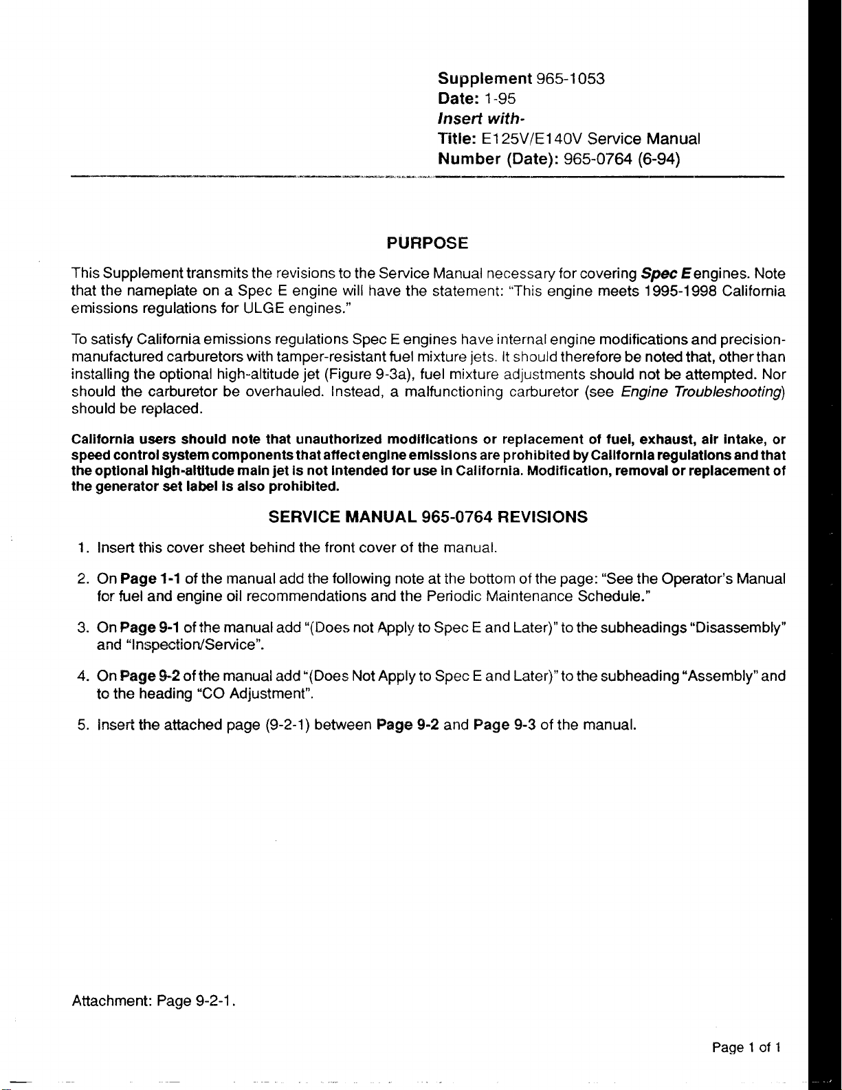
Supplement
Date:1-95
lnsert
Title:
Number
PURPOSE
965-1053
with-
El
25V/E140V
(Date):965-0764(6-94)
Service
Manual
This Supplement transmits the revisions to the Service Manual necessary for covering
that the nameplate on a Spec
emissions regulations for
E
engine will have the statement:
ULGEengines.”
“This
engine meets
Spec
€engines. Note
1995-1998
California
To satisfy California emissions regulations Spec E engines have internal engine modifications and precisionmanufactured carburetors with tamper-resistant fuel mixture jets.
installing the optional high-altitude jet (Figure 9-3a), fuel mixture adjustments should not
should the carburetor be overhauled. Instead, a malfunctioning carburetor (see
It
should therefore be noted that, other than
be
attempted. Nor
Engine Troubleshooting)
should be replaced.
California users should note that unauthorized modifications or replacement of fuel, exhaust, air intake, or
speed control system components that affectengineemissions are prohibited by California regulations and that
the optional high-altitude main jet is not intended for use in California. Modification, removal or replacement of
the generator set label Is also prohibited.
SERVICE
1.
Insert this cover sheet behind the front cover of the manual.
2.On
3. On
Page
1-1
of the manual add the following note at the bottom
for
fuel and engine oil recommendations and the Periodic Maintenance Schedule.”
Page
9-1
of the manual add “(Does not
MANUAL
Apply
965-0764
to
Spec E and Later)”
REVISIONS
of
the page: “See the Operator’s Manual
to
the subheadings “Disassembly”
and “Inspection/Service”.
4.
On
Page
42
of
the manual add “(Does Not Apply
to
the heading
5.
insert the attached page
Attachment: Page
“CO
9-2-1.
Adjustment”.
(9-2-1)
between
Page
to
Spec E and Later)” to the subheading “Assembly” and
9-2
and Page
9-3
of the manual.
Page 1 of
1
Page 7
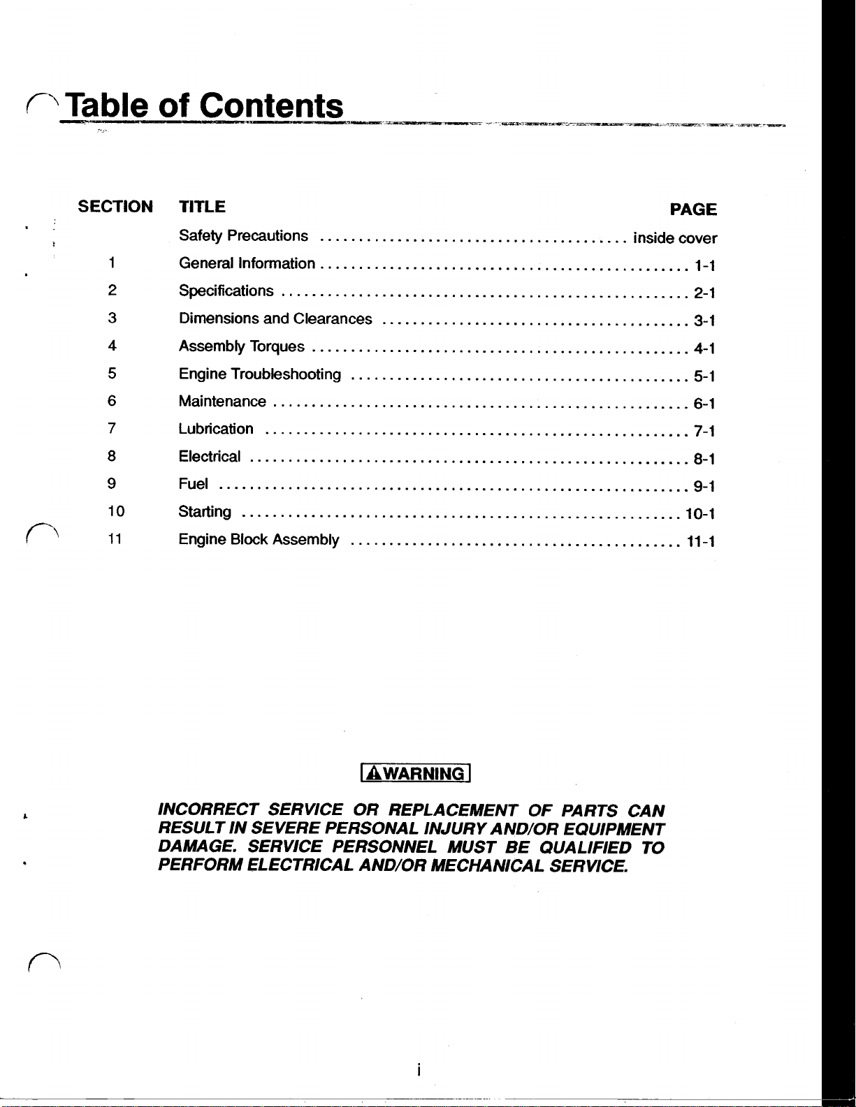
SECTION
TITLE
Safety Precautions inside cover
PAGE
1
2
3
4
5
6
7
8
9
10
General Information 1-1
Specifications 2-1
Dimensions and Clearances 3-1
Assembly Torques 4-1
Engine Troubleshooting 5-1
Maintenance
Lubrication
Electrical
Fuel
Starting 10-1
Block
Engine
Assembly 11 -1
WARNING
INCORRECT SERVICE OR REPLACEMENT OF PARTS CAN
RESULT IN SEVERE PERSONAL INJURY AND/OR EQUIPMENT
DAMAGE. SERVICE PERSONNEL MUST BE QUALIFIED
PERFORM ELECTRICAL AND/OR MECHANICAL SERVICE.
TO
Page 8
Section
1
General Information
INTRODUCTION
This manual provides specific mechanical and
electrical information needed by engine mechanics
for troubleshooting, servicing, or overhauling the
engine.
Use the separate parts manual for parts identification and for establishing their proper location on assemblies. The parts manual contains detailed exploded views of each assembly and the individual
piece part numbers and their proper names for
ordering replacement parts.
The illustrations and procedures presented in each
section apply to the engines listed on the cover. The
air cleaner side of the engine is the front end. Right
and left sides are determined by viewing the engine
from the front.
If
a major repair
trained and experienced mechanic perform the re-
pair and
torque values are within the specified tolerances.
Use the table of contents for a quick reference to the
separate engine system sections.
The troubleshooting guide is provided as a quick
reference for locating and correcting engine
problems.
The wiring diagram shows how the electrical com-
ponents are interconnected.
The
overhaul procedures for step by step removal,
see
Engine
or
an overhaul is necessary, have a
that all dimensions, clearances and
BIock Assembly
section contains major
disassembly, inspection, repair, and assembly of
the engine components.
Use only Genuine Onan replacement parts to pro-
vide quality and the best repair and overhaul
results. When ordering parts, always use the
complete model and spec number as well
serial number shown on the nameplate.
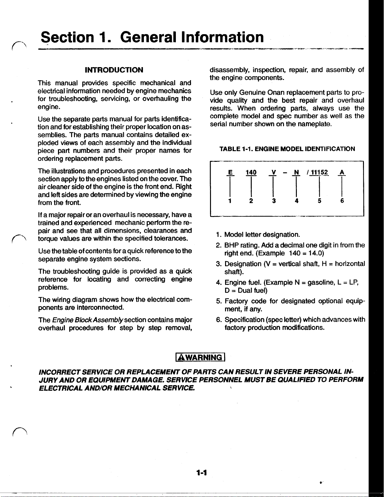
TABLE
1. Model letter designation.
2.
3.
4. Engine fuel. (Example N
5.
6.
1-1.
ENGINE MODEL IDENTIFICATION
BHP
rating. Add a decimal one digit in from the
=
right end. (Example 140
Designation
shaft).
=
Dual fuel)
D
Factory code for designated optional equip-
ment,
Specification (spec letter) which advances with
factory production modifications.
if
(V = vertical shaft,
any.
14.0)
=
gasoline,
H = horizontal
as
L = LP,
the
INCORRECT SERVICE
JURY AND
ELECTRICAL AND/OR MECHANICAL SERVICE.
OR
EQUIPMENT DAMAGE. SERVICE PERSONNEL MUST BE QUALIFIED
OR
REPLACEMENT
OF
PARTS CAN RESULT IN SEVERE PERSONAL IN-
TO
PERFORM
\
Page 9
Section
2.
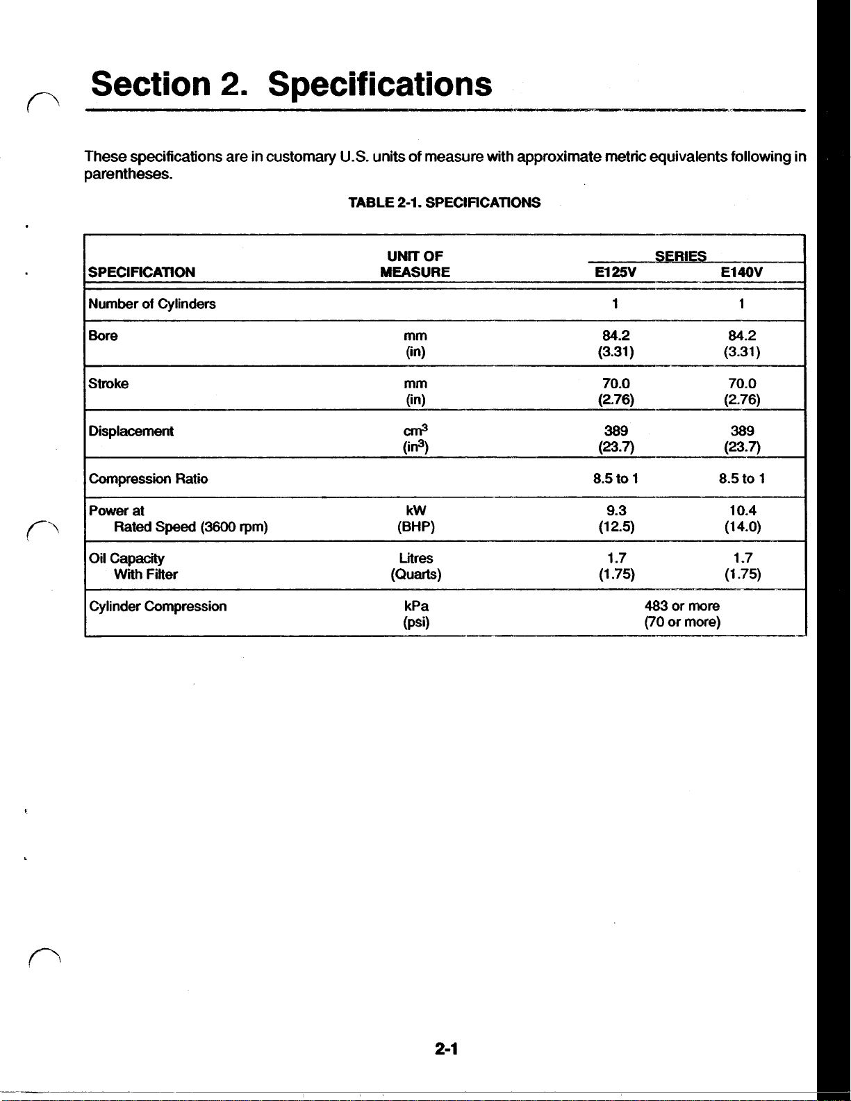
Specifications
These specifications are in customary
parentheses.
SPECIFICATION MEASURE
Number
Bore mm 84.2 84.2
Stroke mm 70.0 70.0
Displacement
Compression Ratio
Power at
Oil Capacity Litres 1.7
of
Rated
With
Cylinders 1
Speed
Fitter (Quarts) (1.75) (1.75)
(3600 rpm)
U.S.
units of measure with approximate metric equivalents following in
2-1.
TABLE
SPECIFICATIONS
OF
UNIT
(in) (3.31)
(in) (2.76) (2.76)
Cm3
(in3)
kW 9.3 10.4
(BW (1 2.5)
El
25V
389 389
(23-7)
8.5 to 1 8.5 to
SERIES
El
4OV
1
(3.31)
(23-7)
(1
4.0)
1
-7
1
Cylinder Compression kPa
(Psi)
483
(70
or
or
more
more)
2-1
Page 10
Section
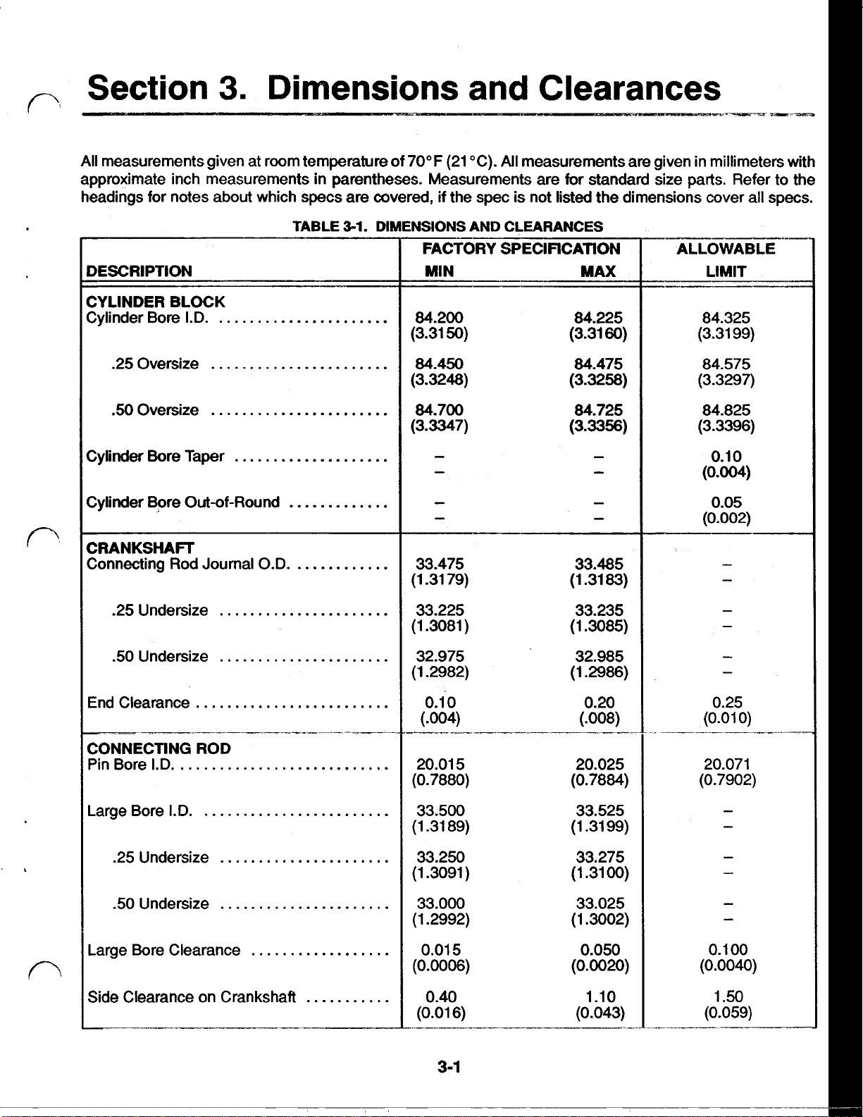
All
measurements given at room temperature of
approximate inch measurements in parentheses. Measurements are for standard size parts. Refer to the
headings for notes
3.
about
Dimensions and Clearances
70°F
(21
"C).
All
measurements are given in millimeters with
which specs are covered,
if
the spec is not listed the dimensions cover all specs.
CYLINDER BLOCK
Cylinder Bore Taper
TABLE
3-1.
DIMENSIONS AND CLEARANCES
Page 11
DESCRIPTION
____-
ALLOWABLE
I
LIMIT
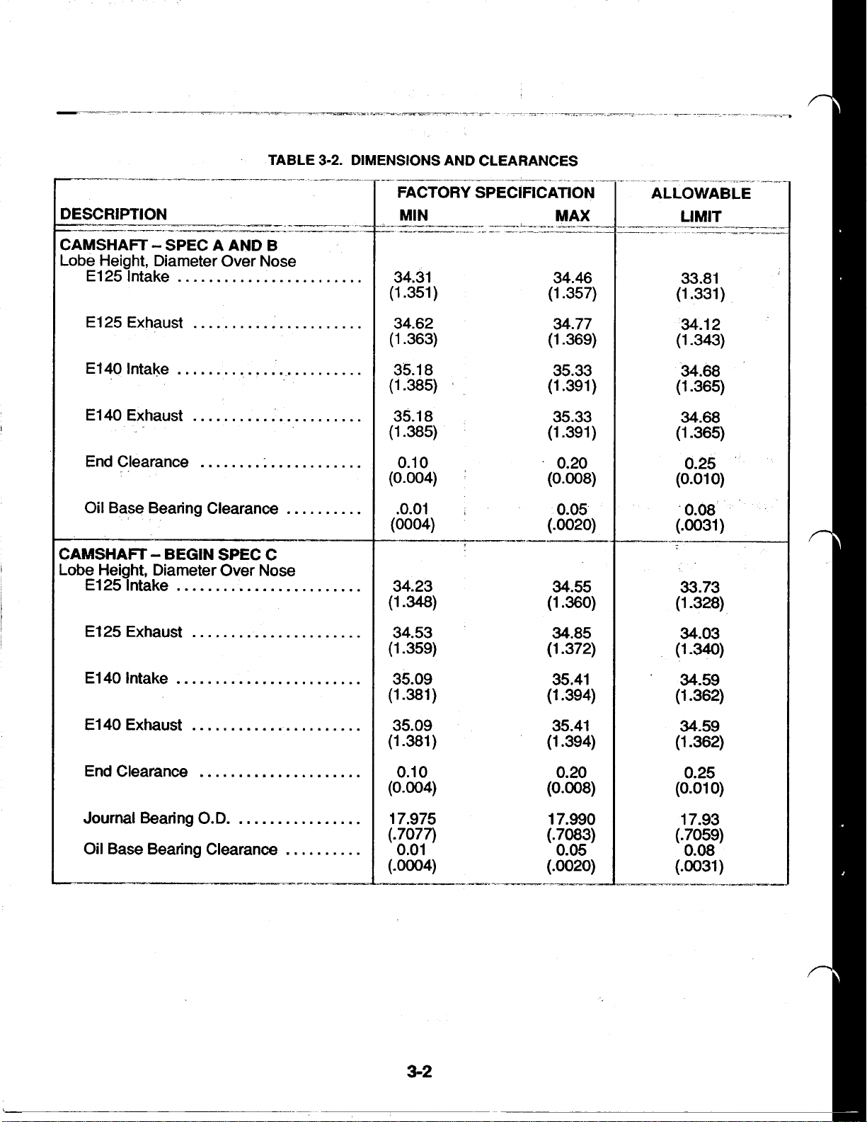
CAMSHAFT SPEC
Lobe- Height, Diameter Over Nose
El25 Intake
El25 Exhaust
E140 Intake
El40 Exhaust
End Clearance
Oil Base Bearing Clearance
A
AND B
CAMSHAFT BEGIN SPEC C
Lobe Height, Diameter Over Nose
El25 Intake
El25 Exhaust
34.31 34.46
(1.351) (1.357)
34.62 34.77
(1.363) (1.369)
35.18 35.33
(1.385) (1.391)
35.18 35.33
(1.385) (1.391)
0.10
(0.004)
.0.01
(0004) (-0020)
34.23
(1-348)
34.53
(1-359)
0.20
(0.008)
0.05
34.55
(130)
34.85
(1.372)
33.81
(1.331)
34.12
(1.343)
34.68
(1.365)
34.68
(1-365)
0.25
0)
(0.01
.0.08
(.0031)
33.73
(1-328)
34.03
(1-340)
El40 Intake
El40 Exhaust
End Clearance
Journal Bearing O.D.
Oil Base Bearing Clearance
-_---
35.09
(1-381)
35.09
(1.381)
0.10
(0.004)
17.975
(.7077)
0.01
(.OOO4)
3-2
35.41
(1.394)
35.41
(1.394)
0.20
(0.008)
17.990
(.7083)
0.05
(.0020)
34.59
(1.362)
34.59
(1.362)
0.25
0)
(0.01
17.93
(.
7059)
0.08
(.0031)
Page 12
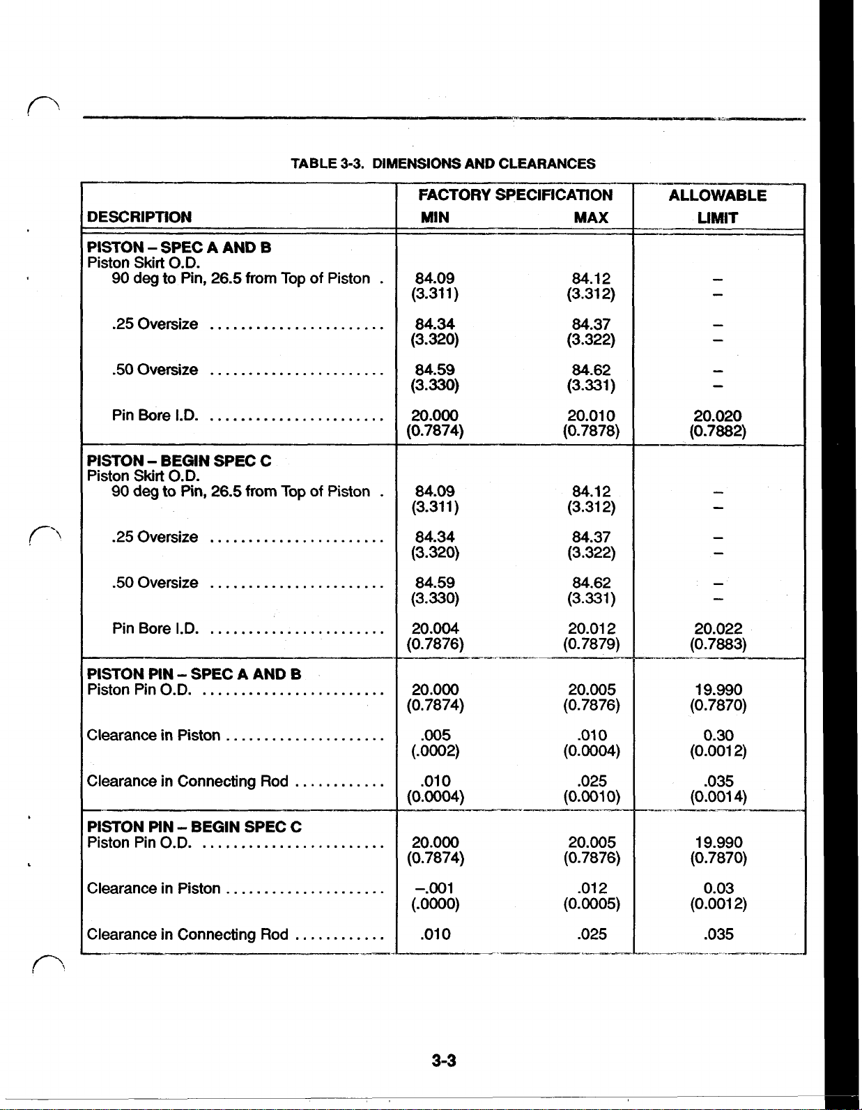
TABLE
3-3.
DIMENSIONS AND CLEARANCES
DESCRlPTlON
PISTON SPEC A AND
Piston Skirt
90
.25
50
Pin Bore
PISTON BEGIN SPEC C
Piston
.25
50
O.D.
deg
to Pin,
Oversize
Oversize
I.D.
Skirt
O.D.
deg
to
Oversize
Oversize
26.5
Pin, from
26.5 90
B
from
Top
Top
of Piston
of
Piston
FACTORY SPECIFICATION
MIN MAX
84.09
(3.31
1)
84.1
2
(3.31 2)
84.34 84.37
(3.320) (3.322)
84.59 84.62
(3.330) (3.331)
20.000
20.01
0
(0.7874) (0.7878)
84.09 84.1
(3.31
1
)
2
(3.31 2)
84.34 84.37
(3.320) (3.322)
84.59 84.62
(3.330) (3.331)
ALLOWABLE
LIMIT
20.020
(0.7882)
Pin Bore
PISTON PIN SPEC A AND
Piston Pin
Clearance in Piston
Clearance in Connecting
PISTON PIN BEGIN SPEC C
Piston Pin
Clearance in Piston
Clearance in Connecting
I.D.
B
O.D.
Rod
O.D.
.....................-.001 .012
Rod
20.004 20.01 2
(0.7876) (0.7879)
20.000
20.005
(0.7874) (0.7876)
.005
.010
(.0002) (0.0004)
.010 .025
(0.004)
20.000
(0.7874)
(.OooO)
.010
(0.001
0)
20.005
(0.7876)
(0.0005)
.025
20.022
(0.7883)
19.990
(0.7870)
0.30
(0.001 2)
.035
(0.001
4)
19.990
(0.7870)
0.03
(0.001 2)
.035
3-3
Page 13
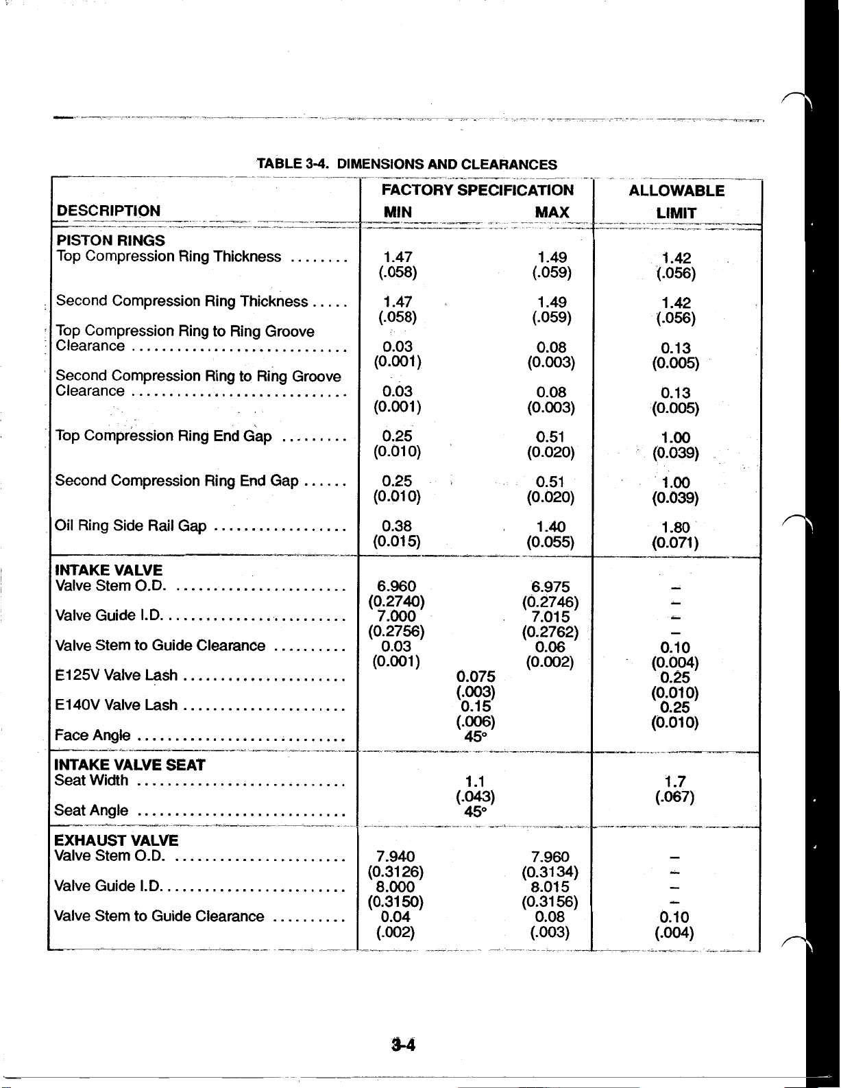
TABLE
3-4.
DIMENSIONS AND CLEARANCES
DESCRIPTION
PISTON
Top Compression Ring Thickness
Second Compression Ring Thickness
Top Compression Ring to Ring Groove
Clearance
Second Compression Ring to Ring Groove
Clearance
Top Compression Ring End Gap
Second Compression Ring End Gap
Oil Ring Side Rail Gap
INTAKE VALVE
Valve Stem
Valve Guide
Valve Stem to Guide Clearance
El
25V
El40V
Face Angle
RINGS
O.D.
I.D.
Valve Lash
Valve
Lash
FACTORY SPECIFICATION
1.47
(.058)
(.059)
1.47
(.058)
(.059)
0.03
(0.001)
(0.003)
0.03
(0.001)
(0.003)
0.25
(0.010) (0.020)
0.25
(0.01
0)
(0.020)
0.38 1.40
(0.01
5)
6.960
(0.2740)
7.000
(0.2756)
(0.055)
6.975
(0.2746)
7.015
(0.2762)
0.03
(0.001) (0.002)
0.075
(-003)
0.15
(-006)
45"
1.49
1.49
0.08
0.08
0.51
0.51
0.06
ALLOWABLE
LIMIT
1.42
t.056)
1.42
(-056)
0.13
(0.005)
0.13
(0.005)
1.oo
(0.039)
1.oo
(0.039)
1.80
(0.071)
(0.004)
0.25
(0.01
0)
0.25
(0.01
0)
INTAKE VALVE SEAT
Seat Width
Seat Angle
EXHAUST VALVE
Valve Stem
Valve Guide
Valve Stem to Guide Clearance
O.D.
I.D.
7.940
(0.31 26)
8.000
(0.3150)
0.04
1.7
(.067)
7.960
(0.31 34)
8.015
(0.31 56)
0.08
(.003)
Page 14
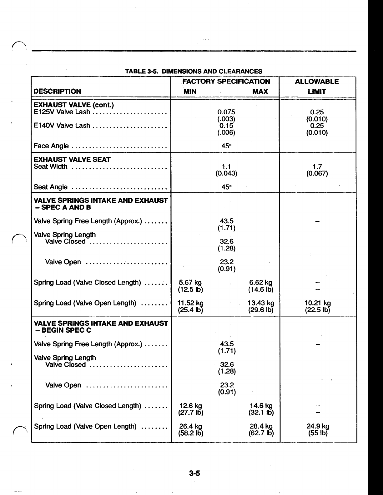
DESCRIPTION
TABLE
3-5.
DIMENSIONS AND CLEARANCES
EXHAUST VALVE
E125V Valve Lash
E140V Valve Lash
Face
Angle
(cont)
EXHAUST VALVE SEAT
Seat Width
SeatAngle
VALVE SPRINGS INTAKE AND EXHAUST
A
SPEC
Valve Spring Free Length (Approx.)
Valve Spring Length
Valve
Valve Open
Spring Load (Valve
AND B
Closed
Closed
Length)
0.075
(-003)
0.1 5
(-006)
45"
43.5
(1.71)
32.6
(1.28)
23.2
(0.91
)
5.67 kg 6.62 kg
(1 2.5
Ib)
(1 4.6
Ib)
0.25
(0.01
0.25
(0.01
1.7
(0.067)
0)
0)
Spring Load (Valve Open Length)
VALVE SPRINGS INTAKE AND EXHAUST
BEGIN SPEC C
Valve Spring Free Length Approx
Valve Spring Length
Valve
Valve Open
Spring Load (Valve Closed Length)
Spring Load (Valve Open Length)
Closed
11
-52 kg 13.43 kg
(25.4
Ib)
43.5
(1.71)
32.6
(1.28)
23.2
(0.91)
12.6 kg 14.6 kg
(27.7
Ib)
26.4 kg
Ib)
(58.2
(29.6
(32.1
28.4 kg
(62.7
3-5
Ib)
Ib)
Ib)
10.21 kg
(22.5
Ib)
24.9 kg
(55
Ib)
Page 15
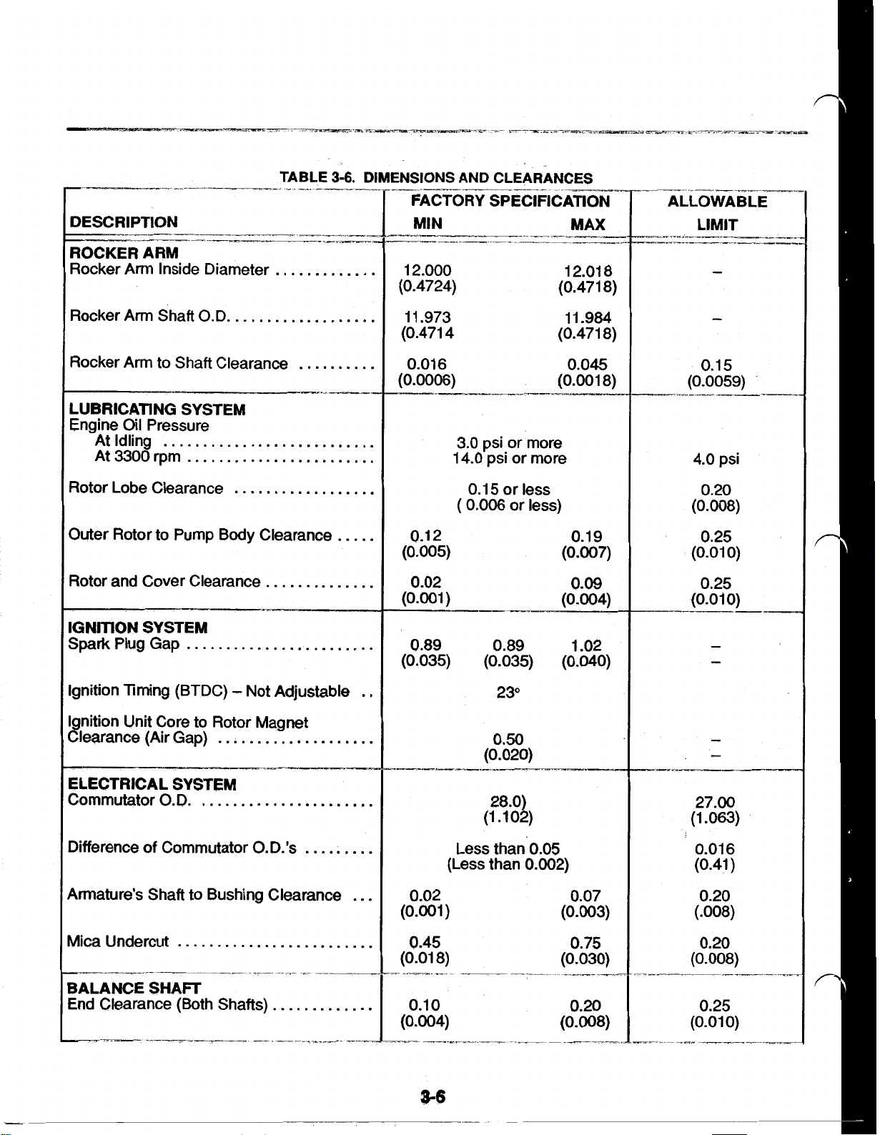
DESCRIPTION
ROCKER ARM
Rocker Arm Inside Diameter
-__.__I-
-"--
AND
CLEARANCES
FACTORY SPECIFICATION
MIN MAX
-_I___-__
12.000
(0.4724) (0.471 8)
12.018
ALLOWABLE
Rocker Arm Shaft O.D.
Rocker Arm to Shaft Clearance
LUBRICATING SYSTEM
Engine Oil Pressure
At Idling
At
3300
rpm
Rotor Lobe Clearance
Outer Rotor to Pump
Rotor and Cover Clearance
IGNITION
Spark
Ignition Timing (BTDC) Not Adjustable
Ignition Unit Core to Rotor Magnet
Clearance (Air Gap)
SYSTEM
Plug Gap
Body
Clearance
ELECTRICAL SYSTEM
Commutator
O.D.
_--
11.973 11.984
(0.4714
0.016
(0.0006)
0.12 0.19
(0.005)
0.02
(0.001) (0.004)
0.89 0.89 1.02
(0.035)
3.0 psi
14.0 psi or more
(
0.15 or
0.006
or
or less)
(0.035)
23"
-I_----*
more
less
(0.471 8)
0.045
(0.001 8)
(0.007)
0.09
(0.040)
0.50
(0.020)
28.0)
(1.102)
0.15
(0.0059)
4.0
psi
0.20
(0.008)
0.25
(0.010)
27.00
(1.063)
Difference
Armature's Shaft to Bushing Clearance
Mica Undercut
BALANCE
End Clearance (Both Shafts).
of
Commutator
SHAFT
O.D.'s
0.02 0.07
(0.001) (0.003)
0.45
(0.01
0.10
(0.004) (0.008)
3-6
Less than' 0.05
(Less than 0.002)
8)
0.75
(0.030)
0.20
0.016
(0.41)
0.20
(.008)
0.20
(0.008)
0.25
(0.01
0)
Page 16
Section
4.
Assembly
Torques
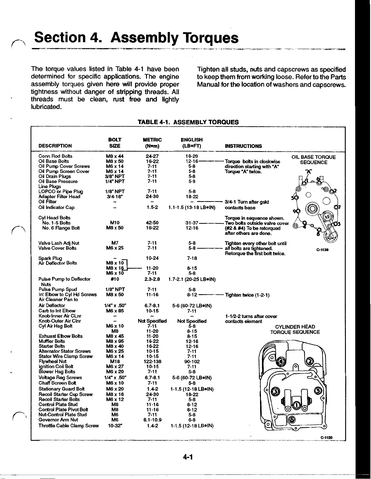
The torque values listed in Table
4-1
have been Tighten all studs,
nuts
and capscrews as specified
determined for specific applications. The engine to keep them from working loose. Refer to the Parts
assembly torques given here
tightness without danger of stripping threads.
threads must be clean,
rust
will
provide proper Manual for the location of washers and capscrews.
All
free
and lightly
lubricated.
DESCRIPTION
Conn
Rod
Base
Bolts
Base
Pressure
Bolts
6
Flange
Deflector
Hsg
Reg
Arm
Bolts
Bolt
Bolt
Bolts
Screws
Stud
Bolt
Nut
Hd
Nut
Screws
Screw
Oil
Oil Pump Cover Screws
Oil Pump Screen Cover
Oil Drain Plugs
Oil
Line Plugs
LOPCO or Pipe Plug
Adapter Filter Head
Oil Filter
Oil Indicator Cap
Cy1 Head
NO. 1-5 Bolts
No.
Valve Lash Adj
Valve Cover Bolts
Spark Plug
Air Deflector Bolts
Pulse Pump to Deflector
Nuts
Pulse Pump Spud
Int Elbow to Cy1
Air Cleaner Pan to
Air
Carb. to Int Elbow
Knob-Inner Air CLnr
Knob-Outer Air Clnr
Cy1 Air Hsg
Exhaust Elbow Bolts
Muffler Bolts
Starter Bolts
Alternator Stator Screws
Stator Wire Clamp
Flywheel Nut
Ignition Coil
Blower
Voltage
Chaff Screen Bolt
Stationary Guard Bolt
Recoil Starter Cup Screw
Recoil Starter Bolts
Control Plate
Control Plate Pivot Bolt
Nut-Control Plate Stud
Governor
Throttle Cable Clamp Screw
TABLE
M8x44 24-27
M8x
50
M6x 14
M6x 14
3/8”
NPT
114" NPT 7-11
1/8” NPT
3/416"
M10 42-50
M8x50 16-22
M7 7-11
M6 x 25 7-11
M8x
M8x 16
M6x 10 7-11
#10 2.3-2.8
118" NPT
50
M8x
114" x .50"
85
M6x
M6x 10
M8
M8x
45
M8X95
M8x
40
M6x
25
M6x 14
M18
M6 x 27
M6x20
114"
x
.50”
M6x 10
M6x
20
M8x 16
M6x 12
M8
M8
M6
M6
1032"
Not
4-1.
16-22
7-11
7-11
7-11
7-11
24-30
1.5-2
10-24
11-20
7-11
11-16
6.7-8.1
10-15
Specified
7-11
11-20
11-20
16-22
16-22
10-15
10-15
122-138
10-15
7-11
6.7-8.1
7-11
1.4-2
24-30
7-11
11-16
11-16
7-11
8.1-10.9
1.4-2
ASSEMBLY TORQUES
18-20 OIL BASE TORQUE
12-16-
58
5-8 Torque
5-8
58
58
18-22
1.1-1.5(13-18LB*IN) contacts
31-37 Two
12-16
5-8
58
7-18
8-15
1.7-2.1 (20-25 LB-IN
58
5-8
8-12
5-6 (60-72 L
7-11
Specified
Not
58
8-15
8-15
12-16
12-16
7-11
7-11
90-102
7-11
5-8
5-6 (60-72
1-1.5 (12-18 LB*IN)
1-1.5 (12-18 LB-IN
LB_IN
58
18-22
5-8
a12
8-12
5-8
68
Toque bolts in
direction
3/41 Turn after gskt
Toque
bolts
(#2
&
#4)
others
after
Tighten
all
bolts
Retorque
Tighten
1-1/2-2 turns after
contacts element
clockwise
starting
'A"
twice.
base
in
sequence shown.
outside
To
be
retorqued
are
done.
every
other bolt
are tightened.
the
first bolt
twice
(1-2-1)
with "A"
valve
cover
until
twice.
cover
CYLINDER HEAD
TORQUE SEQUENCE
SEQUENCE
C-1138
4-1
Page 17
5-1
Page 18
Section
6.
Maintenance
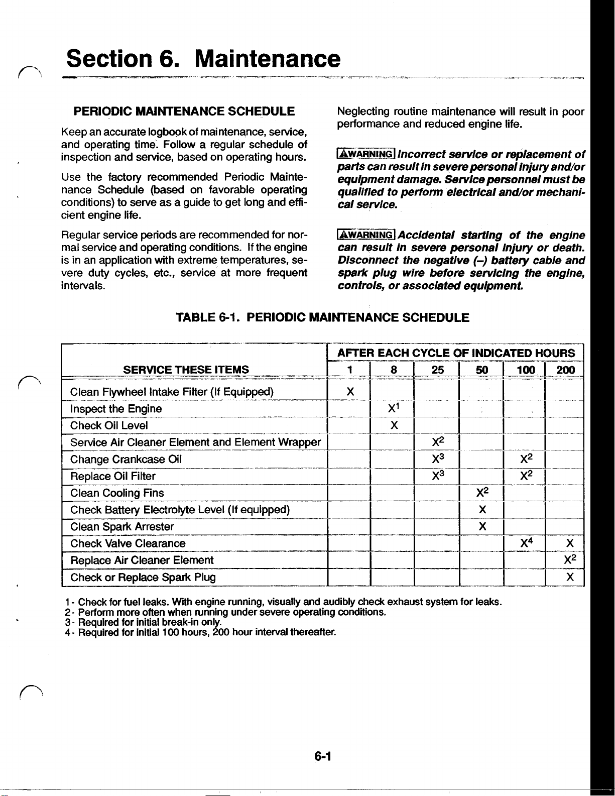
PERIODIC MAINTENANCE SCHEDULE
Keep an accurate logbook of maintenance, service,
and operating time: Follow a regular schedule of
inspection and service, based on operating hours.
Use the factory recommended Periodic Maintenance Schedule (based on favorable operating
conditions) to serve as a guide to get long and efficient engine life.
Regular service periods are recommended for nor-
mal service and operating conditions.
is in an application with extreme temperatures, severe duty cycles, etc., service at more frequent
intervals.
TABLE
If
the engine
6-1.
PERIODIC MAINTENANCE SCHEDULE
Neglecting routine maintenance
performance and reduced engine life.
WARNING
parts
can
equipment damage. Service personnel must
qualified to
cal service.
WARNING Accidental
can result in severe personal Injury or death.
DIsconnect the negative battery cable and
spark
controls, or associated equipment.
Incorrect service or replacement of
result in severe personal Injury and/or
plug
perform
wire
electrical and/or mechani-
starting
before servicing the engine,
will
result in poor
of the engine
be
Air
Cleaner Element and
1
Check for fuel leaks.
2-
Perform more often when running under severe operating conditions.
3-
Required for initial break-in
4-
Required for initial
With
100
engine running, visually and audibly check exhaust system for leaks.
only.
hours,
200
hour interval thereafter.
X
X2
X
Page 19
ENGINE INSPECTION AIR CLEANER AND ELEMENT WRAPPER
Do
Check the fuel lines and fittings for leaks.
start engine until leaks are repaired.
WARNING
in severe personal injury
exhaust system audibly and visualiy for leaks
daiiy and repair leaks immediateiy.
Inspect the exhaust system for cracks and run the
engine to check for leaks. Repair problems before
allowing the engine to
Examine the air cleaner components for damage, Refer to
proper fit, etc. Repair or replace components as service procedures.
necessary.
Check-the oil level with the engine
ment on a level surface.
the full mark on the dipstick, add oil of the proper
viscosity
reaches the
with the oil level
mark.
Breathing exhaust gases can result
or
death. Inspect the
be
used.
off
and the equip-
If
the oil level is at or below
(see
Oil Change
full
mark.
below
section) until the level
Do
not operate the engine
the add or above the
not the and
full
Refer to
Refer to
service procedures.
Refer to
service procedures.
Refer
to
and
service
Refer to
service
Air
Cleaner,
in section
assembly
OIL CHANGE
Oil Change,
in section
OIL FILTER CHANGE
Oil Filter Change,
COOLING
Flywheel,
in section
VALVE CLEARANCE
valve
system,
in
section
procedures.
SPARK PLUG
Spark
procedures.
Plug,
in section
9,
for disassembly,
procedures.
7,
for inspection and
in
7,
for inspection and
11,
for inspection and
for
8,
for inspection and
inspection
Page 20
Section
A
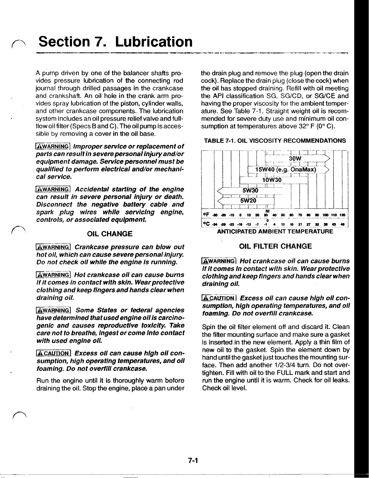
pump driven by one
vides pressure lubrication of the connecting rod
journal through drilled passages in the crankcase
and crankshaft. An oil hole in the crank arm provides spray lubrication of the piston, cylinder walls,
and other crankcase components. The lubrication
system includes an oil pressure relief valve and full-
flow oil filter (Specs
sible by removing a cover in the oil base.
WARNING
parts can result in severe personal injury and/or
equipment damage. Service personnel must be
qualified to perform electrical and/or mechanical service.
Improper service or replacement of
7.
B
and C). The oil pump is acces-
Lubrication
of
the balancer shafts pro-
the drain plug and remove the plug (open the drain
cock). Replace the drain plug (close the cock) when
the oil has stopped draining. Refill with oil meeting
the API classification
having the proper viscosity for the ambient temper-
ature. See Table
mended for severe duty use and minimum oil consumption at temperatures above
TABLE
7-1.
OIL
SG,
SG/CD,
7-1.
Straight weight oil is recom-
VISCOSITY
RECOMMENDATIONS
or
32" F (0"
SG/CE
C).
and
WARNING
can result in severe personal injury or death.
Disconnect the negative battery cable and
spark
controls, or associated equipment.
WARNING
hot oil, which can cause severe personal injury.
Do
not check oil while the engine Is running.
WARNING
if
it
comes in contact with skin. Wearprotective
clothing and keep fingers and hands clear when
draining oil.
WARNING
have determined that used engine oil is carcino-
genic and causes reproductive toxicity. Take
care not to breathe, ingest or come Into contact
with used engine oil.
CAUTION
sumption, high operating temperatures, and oil
foaming. Do not overfill crankcase.
Run the engine until it is thoroughly warm before
draining the oil. Stop the engine, place
Accidental starting
plug
wires while servicing engine,
OIL
CHANGE
Crankcase pressure can blow out
Hot crankcase oil can cause burns
Some States or federal agencies
Excess oil can cause high oil con-
of
the engine
a
pan under
OIL
FILTER
WARNING
if
it comes In contact with skin. Wearprotective
clothing and keep fingers and hands clear when
draining oil.
CAUTION
sumption, high operating temperatures, and oil
foaming. Do not overfill crankcase.
Spin the oil filter element
the filter mounting surface and make sure a gasket
is
inserted in the new element. Apply a thin film
new oil to the gasket. Spin the element down by
hand until the gasket just touches the mounting sur-
face. Then add another
tighten. Fill with oil to the
run the engine until it is warm. Check for oil leaks.
Check oil level.
Hot crankcase oil can cause burns
Excess oil can cause high oil con-
CHANGE
off
and discard it. Clean
1/2-3/4
FULL
turn.
Do
mark and start and
of
not over-
7-1
Page 21

OIL LEVEL
CHECK
WARNING
Crankcase pressure can blow
out
hot oil, which can cause severe personal injury
Do
not check oil while the engine
Correct
sure proper lubrication and prevent saturating the
air cleaner paper element with oil.
Always check the oil with the engine stopped and on
a level surface. When checking the oil level, always
screw the oil
lightly seats on the oil
The
fill
aged, stretched or missing.
oil
level in the crankcase is required to in-
fill
cap into the dipstick tube until it
fill
tube.
oil
fill
cap has a rubber seal that seats on the oil
tube. Inspect this rubber seal and replace
is
running.
if
dam-
OIL PRESSURE
Refer to Figure
tester in the oil
an oil pressure switch
tapped hole. Start the engine. After warming up,
measure the idle and maximum speed oil pressure.
If
oil pressure is not as specified in Dimensions and
Clearances, the following may
engine
clogged
defective
clogged oil gallery
excessive clearance between crankshaft
nal and connecting rod
defective relief valve or spring
Determine cause of
necessary.
oil
oil
7-1.
Install an engine
base
as shown. The engine
or
a
1/8”
be
level
low
strainer
oil
pump
low
oil pressure and
oil
pressure
will
have
pipe plug the
the cause:
correct
jour-
as
FIGURE
7-1.
CHECKING
OIL
PRESSURE
7-2
Page 22

OIL
PRESSURE RELIEF VALVE
Refer to Figure
valve is accessible only after the oil base has been
removed. The check ball and spring are retained by
a retainer ring. On
valve is removable form the outside by removing
the retaining bolt.
Wash all components in solvent and allow them to
dry. Inspect the components for damage and wear.
Replace parts
7-2.
On Specs B and C the oil relief
Spec
A
the oil pressure relief
as
necessary.
SPECS B AND C
I
?
WARNING
Most parts cleaning solvents are
flammable and can cause severe personal In-
jury
or death
If
used
Improperly. Follow the
manufacturer's recommendations when clean-
ing parts.
Lubricate the oil relief valve with oil before assembling. On Specs
and drive it right down to the shoulder of the counter
B
and C use a new retaining ring
FIGURE
7-2.
SPEC
A
OIL
RELIEF VALVE COMPONENTS
7-3
Page 23

Disassembly
OIL
PUMP
Refer to Figure
the oil pump cover to the
7-3.
Remove the capscrews holding
oil
ner and outer rotor.
base. Separate the in-
FIGURE
7-3.
OIL
PUMP DISASSEMBLY
Rotor
Refer to Figure
tween the inner rotor
with a feeler gauge.
in
Lobe Clearance
Dimensions
and
7-4.
Measure the clearance
lobes
If
clearance is not as specified
Clearances,
and the outer
replace
rotor
oil
be-
lobes
pump.
FIGURE
74.
MEASURING ROTOR LOBE
CLEARANCE
-I
*-----
Page 24

Outer Rotor and Pump Body Clearance
Refer
to
Figure
7-5.
Measure the clearance
tween the outer rotor and the pump body with
feeler gauge.
Dimensions and Clearances,
If
the clearance is not as specified in
replace the oil pump.
be-
a
FIGURE
7-5.
MEASURING OUTER
PUMP
BODY
CLEARANCE
ROTOR
TO
Rotor and Cover Clearance
Refer to Figure
7-6.
Place a strip of plastigauge on
the rotor face. Install the pump cover and tighten the
screws to that specified in
ASSEMBLY TORQUES.
Remove the cover carefully and measure the width
of the plastigauge with the table provided.
ance is not as specified in
CLEARANCE,
replace oil pump.
DlMENSlONS AND
If
clear-
Assembly
Prime each part with oil before reassembling.
low
torques given in
tightening hardware. Check
ASSEMBLY TORQUES
oil
pressure after serv-
Fol-
when
icing or replacing any lubrication system compo-
nent.
7-5
-__;--.--
FIGURE
7-6.
MEASURING ROTOR TO COVER
CLEARANCE
Page 25

Section
8.
Electrical
~WARNING~
parts
can result in severepersonalinjury and/or
equipment damage. Service personnel must
qualified to
cal service.
Refer to Figure
high voltage pulse that fires the spark plug each rev-
olution of the engine when the magnet in the rim
the flywheel passes across the pole faces of the
ignition coil. The ignition circuit may include a
throttle plate switch and/or a
switch.
incorrect service or replacement of
be
perform
IGNITION
electrical
and/or mechani-
SYSTEM
8-1.
The ignition coil produces a
low
oil pressure cutout
of
Spark
REMOVAL:Clean the area around the spark plug
fore removing
spark plug. Remove the spark plug from the cylinder head.
Inspection/Service
as recommended
Schedule
spark plugs that show signs of fouling
erosion.
Installation
gap to that specified in
ances.
Never
head.
Tighten spark plug to the torque specified in
SEMBLY
Plug
it.
Remove the spark plug lead from
Check or replace spark plugs
in
the
Periodic Maintenance
(located in Operator's Manual). Replace
or
Refer to Figure
assemble
TORQUES.
a
cold spark plug into a hot cylinder
8-2.
Set spark plug
Dimensions and Clear-
be-
electrode
AS-
FIGURE
8-1
TYPICAL
IGNITION
SYSTEM
8-1
FIGURE
8-1.
SPARK.PLUG GAP
Page 26

Ignition
Spark Test:
spark test as follows:
WARNING
tremely flammable and can cause severe Injury
or
death if ignited. Make certain there are no
gasoline or LPG fumes present before conducting the spark test.
Coil
If
the engine will not start conduct a
Gasoline and LPG vapors are ex-
Measuring Coll/Flywheel Clearance:
Figure
pole face of the coil and the magnet on the flywheel.
If
and Clearances,
screws and adjust to specifications.
8-2.
Measure the clearance between each
the clearance is not as specified in
loosen the
two
Refer to
Dimensions
coil mounting
WARNING
personal injury.
nents while conducting the spark test.
1.
Obtain a test plug or new plug of the same type
as specified for the engine. Disconnect the
spark plug cable from the engine spark plug,
connect it to the test plug and ground the side of
the test plug to bare metal on the engine block.
2.
Crank the engine while looking at the spark
plug.
If
the spark
good.
If
the spark
clearance between the coil and flywheel.
check the condition of the spark plug cable.
the cable appears damaged, replace the ignition coil.
If
there
(throttle plate switch) and oil pressure switch (if
provided) with a jumper to bare metal on the
engine block.
faulty switch.
ignition coil.
ignition voltage can cause severe
Do
not touch Ignition compo-
is
strong, the ignition system is
is
weak, check for and readjust the
Also
is
no
spark,
If
there is now spark, replace the
If
there is no spark, replace the
bypass the kill switch
If
Ignition
Ignition timing is set at the factory and is not adjustable. The solid state ignition components are not
adjustable and require no routine maintenance.
.the engine’s timing is not close to that specified in
Dimensions and
tween the flywheel and crankshaft.
Timing
Clearances
check the key
If
be-
Page 27

FLYWHEEL ALTERNATORS
When the engine is equipped with a
12
VDC starter
motor a permanent magnet flywheel alternator and
be
electronic voltage regulator may
battery charging. Refer to Figure
provided for
8-3.
The flywheel
will have three to six permanent magnets depend-
on
ing
See
the output capacity.
Section 10. Starting
regarding starter
motor
service.
When the engine
equipped with a
110
VAC starter
is
motor and/or recoil starter a permanent magnet fly-
wheel alternator and
full
bridge rectifier may be pro-
vided for the customer DC interface (clutch, hour
meter, etc.). Refer to Figure
8-4.
The
110
VAC starter is provided with a power cord connected to a
switch /power receptacle block for mounting on the
equipment.
See
Section
10.
Starting
regarding starter motor
service.
FIGURE
SYSTEM FOR BATTERY CHARGING AND
8-3.
TYPICAL FLYWHEEL ALTERNATOR
STARTER
12
VDC
a-3
FIGURE 8-4. TYPICAL FLYWHEEL ALTERNATOR
SYSTEM FOR CUSTOMER DC INTERFACE AND
110
VAC STARTER
Page 28

Alternator
Keep the following points in mind when testing or
servicing the flywheel alternator.
CAUTION
and negative
connection to
Output
Operatlon with reversed
(-)
Tests
positive
battery connections or without
a
battery
wlll
damage the voltage
(+)
regulator and/or the alternator stator.
1.
Never reverse the battery leads.
2.
Charging system tests require a fully charged
battery in good condition. Make sure the engine is being run long enough and fast enough
in service to recharge the battery after each
start (engines with
output is proportional to engine speed and accessories consume power otherwise available
for battery recharging.
3.
The voltage regulator has built in protection
against open circuit and short circuit faults
terminal). It will not "turn on" under either condition or when battery discharge is extreme.
4.
Check to see that the connections at the terminals of the voltage regulator (three) or of the
rectifier bridge (four) are clean and tight.
5.
Check to
B+
terminal (middle) of the voltage regulator or
to the
are not damaged, shorted or grounded.
6.
To ensure a, good ground path to battery negative
mounting surface is clean and that the screws
are tight.
6.
Check
tery cables have good connections at the battery and engine and that they are not damaged.
After checking all of the above perform the following
tests
if
there
see
+
and terminals of the bridge rectifier
(-),
check to
to
see that the positive and negative bat-
still
is no alternator output when the en-
12
VDC starters). Alternator
that the wiring connected
see
that the voltage regulator
to
)B+
the
gine is running between
to Table
ter (Simpson
1.
2.
3.
4.
5.
8-1
for test specifications.
270)
Check battery voltage when the engine is not
running. (Not applicable on recoil or
starter engines.)
(Table
Step
With the engine running, check voltage regulator output (DC voltage) at the battery terminals
or
cable. Replace the
is greater than specified.
bridge' rectifier output is less than specified, go
to Step
Disconnect the alternator stator leads from the
voltage regulator
alternator stator output (AC voltage) with the
engine running.
specified, go to Step
specified but voltage regulator or bridge rectifier output is
bridge rectifier.
Shut down the engine and check for electrical
resistance between either alternator stator
lead and ground (bare engine metal) with an
ohmmeter. The meter should indicate infinite
resistance on its highest scale.
high, go to Step
Check alternator stator resistance by'connecting an ohmmeter across the stator leads. Replace the alternator stator assembly
sistance on the lowest scale of the meter is either higher or lowerthan specified. Replace the
flywheel assembly
tance
is
loss
8-l),
charge the battery before going to
2.
bridge rectifier output (DC voltage), as appli-
3.
low,
is
as specified but alternator stator output
less than specified. The probable cause is
of magnetism.
1800
and
3600
RPM.
Use
a multi-me-
when testing the alternator.
11
0
If
not within specifications
voltage
or
bridge rectifier and test
If
stator output is less than
replace the voltage regulator or
5.
If
not, replace the stator.
if
regulator
If
voltage regulator
4.
If
stator output is as
If
alternator stator resis-
if
resistance is
If
stator re-
Refer
VAC
output
or
for
Page 29

ALTERNATOR
Non-Battery
Charging
Alternator
5 Amp
Battery
Charging
Alternators
15Amp
Battery
Charging
Alternators
20 Amp
Battery
Charging
Alternators
A
Spec
2.5 Amp
Battery
Charging
Alternator
BATTERY
VOLTAGE
12 to 13
VDC
12 to 13
VDC
12 to 13
VDC
12 to 13
VDC
TABLE
8-1.
VOLTAGE
REGULATOR
OUTPUT
13.6 to 14.7 VDC
at Any Speed in
Operating Range
13.6 to 14.7 VDC
at Any Speed in
Operating Range
13.6 to 14.7 VDC
at
Any
Operating Range
ALTERNATOR OUTPUT TEST SPECIFICATIONS
BRIDGE
RECTIFIER
OUTPUT
Approx.
at 1800
Approx.
at
3600
30
RPM
60
RPM
VDC
VDC
ALTERNATOR
STATOR
OUTPUT
Approx. 29 VAC
at 1800
RPM
Approx. 57 VAC
at 3600
Approx. 29
at 1800
RPM
VAC
RPM
Approx. 57 VAC
at
3600
RPM
Approx. 29
at 1800
VAG
RPM
Approx. 57 VAC
Speed
in
at 3600
Approx.
at
Approx. 57 VAC
at
1800
3600
RPM
29
RPM
RPM
VAC
ALTERNATOR
STATOR
RESISTANCE
0.27-0.33
Ohms
0.27-0.33 Ohms
0.54-0.66
0.54-0.66
0.30-0.36
Ohms
Ohms
Ohms
Page 30

.
Section 9. Fuel
k-l
~AWARNING]
Incorrect service or replacement of
parts can result in severe personal injury and/or
equipment damage. Service personnel must be
qualified to perform electrical and/or mechanlcal service.
/AWARNING
1 Accidental starting of the engine
can result in severe personal injury or death.
Disconnect the negative battery cable and
spark plug wires while servicing engine, con-
trols, or associated equipment.
[AWARNING]
Ignition of fuel can result In severe
personal injury or death. Do not smoke or allow
any spark, pilot light, or arcing switch or eguipment near the fuel system or in areas with
shared ventilation.
GASOLINE CARBURETOR
Disassembly --
Carburetor parts are delicate and must be handled
with care. Never force parts when disassembling or
assembling.
not applicable, Sp& E
IDLE MIXTURE
FLOAT
LOW IDLE
MAIN
JET
Remove the air cleaner assembly and disconnect
the fuel line and throttle and choke links. Remove
the carburetor assembly from the intake manifold.
Refer to Figure 9-1 for Spec C and to Figure 9-2 for
Specs A and B. Remove the float bowl, slide the
float pin out and remove the float and float valve.
Remove the main jet and idle adjusting screw and
spring. For Specs A and B also remove the main
nozzle, passage cover and slow jet.
Inspection/Service -
Soak metal components in carburetor cleaner. Do
not soak non-metal parts and gaskets. Follow the
cleaner manufacturer’s recommendations and
safety precautions.
Clean carbon from the carburetor bore, especially
around the throttle and choke plates. Dry out all
passages with low (35 psi) air pressure. Do not use
wire or other objects for cleaning passages as doing
so may damage the critical passages.
Replace the float if it is cracked, damaged, or
loaded with fuel.
not applicable
SPec E
FLOAT
BOWL
FIGURE 9-1. GASOLINE CARBURETOR (SPEC C)
9-I
Page 31

CARBURETOR (BEGINNING SPEC
E)
Carburetor Replacement
Other than replacing the carburetor main fuel jet
(fixed-type) with the optional high-altitude jet
(Fig-.
ure9-3a),fuelmixture adjustments should not be
attempted. Nor should the carburetor be over-
hauled. Instead, a malfunctioning carburetor should
be replaced. Before replacing a carburetor, however, make certain
1)
that all other necessary engine
and generator adjustments and repairs have been
performed and
malfunctioning {see
To
remove the carburetor, remove the air cleaner
2)
that the carburetor is actually
Engine
Troubleshooting).
and air cleaner base, disconnect the fuel line and
choke and throttle linkages and unbolt the carburetor from the intake manifold. When mounting the
carburetor always use new gaskets. Readjust the
choke and throttle cables and engine speed as
instructed in the engine or equipment Operator’s
Manual.
Carburetor High-Altitude Jet (Optional)
TAMPER-RESISTANT
PLUG
OVER
MIXTURE
STOP
IDLE
NEEDLE
SCREW
THROTTLE
LEVER
CHOKE
LEVER
If
the engine
feet
(1,524
is
operated at an altitude above
metres),
buretor main fuel
high-altitude
jet
fice).
CAUTION
maln
fuel
(8
mm)
To
jet
use
wide blade.
5,000
it
is recommended that the car-
jet
be replaced with the optional
(which has a slightly smaller ori-
avoid slipping
a screwdriver wlth
and
gouging the
,a
5/16
inch
FIGURE
9-3a.
CARBURETOR
Page 32

Replace the carburetor
the choke and throttle shafts.
if
there is excessive play
in
Replace the idle adjustment needle
or
damaged in
any
way.
if
it
is bent, worn
Assembly
CAUTION
easiiy damaged. Turn the mixture adjustment
screw in only until light tension
When installing the idle adjusting screw, turn the
screw in until LIGHT tension is felt. For Spec
the screw
the screw
Turn the carburetor body upside down to assemble
the main jet, main nozzle (Specs
valve, float and float bowl as illustrated in Figure 9-1
or
9-2.
Torque the carburetor mounting
specified in
fuel line and throttle and choke links and secure the
air cleaner assembly.
See the instructions that follow in this section
governor, choke and
The mixture adjustment screw is
can
be
out
3-1/8 turns. For
out
2-1/2
turn.
ASSEMBLY
speed
Specs
A
bolts
TORQUES,
adjustments.
A
and B turn
and
to
the torque
reconnect the
feit.
C
B),
turn
float
for
LOW
IDLE
Co
Adjustment
If
a
CO
(Carbon Monoxide) meter is available, ad-
just the idle mixture screw to provide
at
3300
rpm
with
no load on the engine.
not available, set the idle mixture screw at
turns
out
(Spec
B)
as noted above.
C)
or
2 1/2
turns
6%
to
If
a meter
out
(Specs A and
7%
CO
is
3-1/8
FIGURE
9-2.
GASOLINE
(SPECS
CARBURETOR
A
AND
B
FLOAT
CHAMBER
)
9-2
Page 33

IMPULSE FUEL .PUMP
The engine may be equipped with an impulse type
fuel pump that uses crankcase pressure (vacuum)
pulses to operate a spring loaded diaphragm inside
the pump to pump the fuel through
valves. Engine crankcase vacuum is connected
through a hose to the back of the pump. The fuel
flow direction is marked on the cover of the pump.
two
check
performance.
tube.
7.
If
the gasoline has been stored for an extended
time, drain and properly dispose of the old gasoline. Refill the fuel tank with fresh unleaded
regular gasoline.
If
fuel delivery problems still occur, perform the fol-
lowing performance checks based on the symptom.
Also
check the seal
on
the oil
fill
Use
adequate ventilation when working on the fuel
system. Prevent ignition sources in the areas sharing ventilation.
If
the fuel pump leaks, replace it. This fuel pump is
a
not intended to be rebuilt for
WARNING
ignition
of
fuel can result in severe
personal injury or death.
any spark, pilot light, or arcing switch
fuel leak problem.
Do not smoke
or
or
allow
equip-
ment near the fuel system or in areas with
shared ventilation.
Inspection/Service
If
a problem with fuel delivery to the engine is
pected, check the following items before inspecting
the fuel pump.
1.
Make sure the fuel shutoff valve is open.
2.
Check the fuel filter and replace
3.
Make sure the fuel hoses are not kinked or
pinched, causing a fuel restriction. Dips and excessively long runs of fuel line in a hot area can
cause vapor locking.
4.
Check the fuel tank cap for a restricted vent.
5.
Check the oil level to make sure
mark.
6.
Inspect the crankcase, especially at the gaskets, for visible oil leaks, indicating crankcase
air leakage that can cause reduced fuel pump
it
if
it
is at the full
sus-
required.
Engine
mediately remove and inspect the spark plug.
If
the
check for:
If
the
ignition sparks can not ignite the gasoline.
Remove the fuel line from the carburetor and splice
in a
Place the end of the fuel line in
the gasoline Crank the engine with the electric
starter
should be fuel flow into the container.
fuel flow from the pump, replace the fuel pump
instructed in this section.
Engine Runs But
If
the engine starves for fuel at high load, connect a
gravity feed fuel supply directly to the carburetor.
Plug the fuel line from the fuel pump during this test.
If
the gravity feed fuel supply eliminates fuel starva-
tion, replace the fuel pump
tion.
not the cause.
Will
Not
Start:
plug
is
wet and
An ungrounded ignition ground wire
A
defective throttle plate or low oil pressure
switch or other equipment switch for ignition
grounding
A fouled spark plug
An improperly adjusted carburetor choke
plug Is
fuel
If
the fuel starvation continues, the fuel pump is
dry,
ground the spark plug lead
line of approximately eight inches in length.
or
the recoil starter for
Crank the engine, then im-
it
has a strong gasoline odor,
so
a
container to collect
20
seconds. There
If
there is no
Will
Not Operate At High Load:
as
instructed in this
that'
as
sec-
9-3
Page 34

Fuel
Pump
Refer to Figure
rebuilt and should be replaced as a complete as-
sembly. pump (it may
1.
Turn
2.
Place a drip pan under the fuel pump and car-
buretor to collect fuel.
3.
Disconnect the starting battery (if equipped).
Disconnect the negative
duce the risk of arcing.
4.
Remove the air cleaner cover and air filter
assembly.
5.
Loosen the screws that secure the fuel pump to
the air cleaner pan assembly.
6.
Disconnect the pulse hose from the fuel pump.
'Removal
9-3.
The pump is not intended to be
off
the fuel shutoff valve at the tank.
(-)
cable first to re-
7.
Disconnect the inlet -fuel hose from
pump.
8.
Disconnect the outlet fuel hose
cleaner
the fuel pump).
9.
Remove the fuel pump.
Fuel
Pump
Install the new fuel pump in reverse order
al. Replace any damaged or deteriorated fuel lines.
After installation, check governor and engine speed
adjustments for proper engine response.
Tighten all mounting hardware to that specified in
Assembly
pan
lnstallation
Torques.
the
fuel
from
the
fuel
be
necessary
mounting screws to gain access to
to
loosen
of
the
air
remov-
IMPULSE
9-4
FUEL
Page 35

LPG
FUEL
Refer to Figure
regulator, air pump and vacuum sustain valve comprise the
of the engine assembly.
provided by the equipment manufacturer.
The carburetor should not require service and there
are no replaceable parts or adjustments except for
the low idle speed screw.
LPG
WARNING
The Idle mixture screws
gas pressure regulator are factory set and
sealed.
Note: It is the responsibility
tain that indoor carbon dioxide regulations
The air pump
illustrated in Figure
DO
9-4.
fuel system components that are part
Carbon Monoxide
NOT
READJUST.
is
identical to the gasoline fuel pump
9-3.
SYSTEM
The carburetor, gas pressure
A
vacuum cutout device is
(CO)
Is deadly!
on
the carburetor and
of
the user to make
are
cer-
met.
Referring to the block diagram,. operation of the
LPG
fuel system is as follows:
1.
Crankcase vacuum
to pump clean air from the air cleaner to the
vent side of the gas pressure regulator, which
has a factory adjusted and sealed bleed valve.
This provides for a precisely adjustable flow of
gas for proper idle mixture.
2.
The vacuum sustain valve consists of a check
valve and bleed-off
case vacuum when the engine stops to cause
the vacuum lock-out device to shut off the gas
supply. The check valve removes the vacuum
pulses permitting the
during cranking.
See
the instructions that follow in this section for
governor, choke and speed adjustments.
pulses
orifice.
lock-out
cause the air pump
It
bleeds off crank-
device to open
PEED SCREW
I
LPG
I
I I
L----,,,
SUPPLY
TANK
I
I
I
I
I
I
I
I
LPG CARBURETOR
CRANKCASE VACUUM
VACUUM
PULSES
PRESSURIZED
AIRPUMP
AIR REGULATOR
I
I
Device
PRESSURE
I
I
I
t
AIR
CLEANER
I
FIGURE
9-4.
LPG CARBURETOR AND FUEL
9-5
SYSTEM
BLOCK DIAGRAM
Page 36

GOVERNOR
In order to obtain the best performance from the
equipment it is essential that the governor lever, low
and high idle speeds, choke and speed control
cable be adjusted properly.
Symptoms of improper adjustment are: excessive
loss
of engine speed under load, engine stalling,
no-load speed surging, poor starting and spark plug
fouling.
The equipment Owner's Manual
and high idle speed settings for optimum performance. Always set engine speed with an accurate tachometer. Never exceed the high speed setting
specified by the equipment manufacturer.
The order of adjustments in this section
followed in order to obtain proper adjustments. The
order is as follows:
1.
Governor Lever Adjustment
2.
Idle Speed Adjustments
3.
Choke Adjustment
4.
Speed Control Cable Adjustment
1.
Governor Lever
Refer to Figure 9-5. The proper angular relationship
between the governor lever and the governor shaft
is essential for obtaining the
speed/load performance. The position of the governor lever should be readjusted whenever the intake
manifold is reinstalled after removal for service.
Governor Lever Removal:
Spec C gasoline engines is secured to the tapered
governor shaft with a nut. On LPG and Spec A and
ADJUSTMENTS
will
specify the low
Adjustment
full
range of engine
The governor lever on
MUST
be
Spec
around the straight shanked governor shaft with a
draw bolt and nut. Before removing the lever, stop
the engine and disconnect the throttle link and governor spring. For Spec
standard battery cable clamp lifter available at any
automotive parts store to break the tapper fit between shaft and lever hub.
stopped to assemble and adjust the lever.
B
gasoline
Governor Lever
1.
Loosely assemble the governor lever and shaft
so
that the lever is free to rotate about the shaft.
2.
Attach the throttle link between the governor lever and carburetor. Replace the nylon clips
they are
3.
Attach the governor spring, move the throttle
control lever to align the lock pin holes in the
control plate and throttle control lever and insert a pin
9-6.
4.
Check to see that the governor spring is holding the carburetor throttle plate in the wide
open position.
5.
For Spec C gasoline engines tighten the lock
nut on the end
sure the 'governor shaft rotates clockwise
against the internal governor parts, and torque
to specifications. For LPG and Spec
Spec
screwdriver to rotate the governor shaft clock-
wise
tightening the lever draw
6. Remove the
trol lever and proceed to the next adjustment.
B
against the internal governor parts while
engines the lever is clamped
C
gasoline engines use a
Adjustment: The
worn
or broken.
to
lock the lever in place.
of
the governor shaft making
gasoline engines
lock
pin to release the throttle con-
engine must be
use
a flat-bladed
bolt.
See
Figure
A
and
if
Page 37

I-
CONTROL
LEVER
SPEC C GASOLINE
ENGINES
GOVERNOR
SHAFT
SPEC
FIGURE
LPG ENGINES
B
GASOLINE
9-5.
ENGINE GOVERNOR
ENGINES
9-7
LEVER
GOVERNOR SPRING
SPEC A
GASOLINE
ENGINES
Page 38

2.
Idle
speed
WARNING
severe personal injury
manufacturer’s speclfications for
Adjustments
Too high
a
speed
settlng can cause
or
death-
Follow the
low
and high
idle speeds as found in the equlpment Owner’s
Manual. Use an accurate tachometer
SPEED
CONTROL
CABLE
CLAMP
9/64
LOCK
IN.
PIN
(3.5
HOLE
mm
High Idle
1.
Speed
Set up the tachometer according to the instruc-
Adjustment;
Refer to Figure
tions with the tachometer.
2.
Start the engine according to the equipment
manufacturer’s recommendations, observing
all safety precautions, and allow the engine to
warm up for at least
3.
While the engine
controi lever to align the
10
minutes.
is
running move the throttle
lock
pin holes in the
control plate and throttle control lever and insert a pin to lock the lever in place. Loosen the
speed control cable clamp
if
necessary.
4. Loosen the choke rod clamp screw and push
the choke rod towards the carburetor
the choke will be fully open.
5.
High idle speed is adjusted by rotating the con-
trol plate around the pivot bolt-away from the
carburetor to increase speed and toward the
carburetor to decrease speed. Therefore,
en the control plate pivot
the control plate set
idle
speed
to that specified by the equipment
bolt
bolt
1/8
turn and the
1/4
turn. Adjust high
manufacturer, tighten the control plate bolts,
recheck speed and readjust
if
necessary.
so
9-6.
that
loos-
CONTROL
PLATE
FIGURE
9-6.
HIGH
IDLE SPEED ADJUSTMENT
CONTROL
PLATE
PIVOT
BOLT
6.
Remove the lock pin to release the throttle con-
trol lever.
bow
Idle
Speed
1.
Continue running the engine with
ter connected and move
ver to the
2.
Adjust engine speed
speed by’
the carburetor. See Figure
appropriate. Shut
Adjustment;
low
idle speed position.
to
turning
the
low idle speed screw on
off
the engine and proceed to
Refer to Figure
the
tachome-
the
throttle
control
the specified low idle
9-1, 9-2
or 9-4, .as
the choke adjustment.
9-7.
le-
-LOW
IDLE
.POSITION
ME
THROTTLE
CONTROL
SPEED
OF
LEVER
Page 39

3.
Choke
Adjustment
Refer to Figure
9-8.
Proper choke adjustment is essential for obtaining consistent starting at low temperatures and wide open operation under normal
running conditions.
1.
Shut
off
the engine and loosen the choke rod
so
clamp screw
that the rod is free to move
in
the choke swivel.
2.
Move the throttle control lever to align the lock
pin holes in the control plate and throttle control
lever and insert a pin, making sure the pin ex-
tends past the choke lever to function as a stop
for
the choke lever.
3.
Push the choke rod towards the carburetor to
make sure the choke is fully open.
4.
Rotate the choke lever towards the carburetor
until the lever bears against the pin stop.
5.
Tighten the choke rod clamp screw. For Spec
gasoline engines there must be a
inch (0.25 to
0.76
mm) gap, as shown, between
0.01
to
A
0.03
the choke and throttle control levers.
6.
Remove the air filter paper element and check
that the choke is fully open. Remove the lock
pin in the control plate and check operation
the choke linkage.
If
the linkage binds, replace
of
the components that are damaged.
7.
Proceed to the following
speed
control cable
adjustment.
MAKE
LOCK
PAST
LEVER
AS
A
STOP
SPECS
SURE
THE
PIN EXTENDS
THE
CHOKE
TO FUNCTION
FOR
LEVER
THE
BAND
SPEC
A
C
9/64
IN.
(3.5
mm)
9-9
0.01
(0.26
to
FIGURE
to
0.03
0.76
GAP
in.
mm)
9-8.
CHOKE ADJUSTMENT
Page 40

4.
Speed
Control Cable Adjustment
Refer to Figure
9-9.
The speed control cable must
be installed properly to obtain full-load, full-speed
operation. Adjust the speed control cable as fol-
lows:
1.
Stop the engine and loosen the speed control
cable clamp located on the engine throttle control plate.
2.
Push the speed control lever on the equipment
to the high speed position. On equipment without a separate choke control be sure the speed
control lever is not in the start or choke position.'
3.
Move the throttle control lever to align the lock
pin holes in the control plate and throttle control
lever and insert a pin to lock the lever in place.
4.
Remove the slack
from
the speed control cable
and tighten the speed control cable clamp. Remove the lock pin in the control plate.
5.
Start the engine according to the equipment
manufacturer's recommendations, observing
all safety precautions.
SPEED CONTROL
CABLE CLAMP LOCK PIN
PULL CABLE
THIS
WAY
TO
CABLE
SHEATH
REMOVE
SLACK
9/64
IN
(3.5
HOLES
mm)
ALTERNATE SPEED
CONTROL
CLAMP LOCATION CONTROL LEVER
CABLE
TYPICAL EQUIPMENT
FIGURE
9-9.
SPEED
ADJUSTMENT
SPEED CONTROL
CONTROL
\
THROTTLE
CABLE
Page 41

AIR
CLEANER
Install the foam wrapper over the paper air cleaner
element by stretching over the inner cover.
Foam Wrapper Element
pletely cover all exposed paper pleats on the air
cleaner paper element.
Refer to Figure
for
foam wrapper service interval. Remove the
9-9.
See Periodic Service Schedule
stretched
per. Assemble the outer air cleaner cover and nut.
outer air cleaner nut and plastic outer cover. When
servicing the foam wrapper only
Do
NOT
remove
the inner air cleaner nut and inner cover.
Wipe away loose dirt and chaff from the air cleaner
assembly and then remove the foam wrapper by
pulling the foam wrapper over the inner cover. Wash
Paper Element
Refer to Periodic Maintenance Schedule for air
cleaner service and replacement interval. Service
or
operating conditions.
the foam wrapper in water and detergent and
squeeze dry like a sponge. Rinse with water.
Dry
the
foam wrapper by compressing between several
sheets of paper toweling. Apply
2
tablespoons of
new engine oil and knead into the foam wrapper until it is evenly distributed. Remove excess oil by
compressing the foam between several sheets of
paper toweling. Failure to remove excess oil
will
cause the paper air cleaner to become oil soaked.
loss
This will cause a
in engine performance and a
shortened paper air cleaner element life.
cover. Wipe away loose dirt and chaff from the air
cleaner assembly and then remove the inner air
cleaner nut and inner air cleaner cover. Remove the
air filter paper element and foam wrapper from the
engine. Wipe off excess dirt from air cleaner base
and install the new paper element, inner cover and
inner nut. lighten the inner nut one and a half turns
after seating on the inner cover. Service the foam
wrapper per the instructions given above. Assemble the outer air cleaner cover and nut.
Com-
If
the foam wrapper has
or
become tom, replace the foam wrap-
replace more often when operating under severe
Remove the outer air cleaner nut and plastic outer
GASOLINE ENGINES SPECS
LPG ENGINES
A AND
B)
GASOLINE ENGINES (SPEC C)
Page 42

Section
10.
Starting
WARNING
parts
can result in severe personal injury and/or
equlpment damage. Service personal must
qualified to
cal service
WARNING
can result In severe personal Injury or death.
Disconnect the negative
spark
controls, or associated equlpment.
Disassembly:
four capscrews holding the recoil assembly on the
engine. Remove the recoil assembly from the
blower housing.
Inspection/Service
unit. The
sion, pulling the
slack. When pulling the rope
should come out of their cup and they should not
bent, broken, or missing.
Assembly;
housing. Install and torque the four capscrews to
the torque specified in
Incorrect service or replacement of
perform
Accidental starting of the englne
plug
wife before serviclng the englne,
RECOIL
Refer to Figure
rope
should pull out freely with spring ten-
Place the recoil assembly on the blower
electrical and/or mechanl-
(-)
battery cable and
STARTER
10-1.
Remove the
Inspect the assembly as a
rope
back in without binding or
out,
the
dog
Assembly
Torques.
ears
be
be
110
VAC STARTER
Disassembly:
two
drive cap mounting screws and remove the as-
sembly from the engine.
Inspection/Servlce:
switch/motor assembly
ate or is not strong enough to turn the engine. Replace the pinion gear and associated parts
ion is worn and/or binds on the shaft. The parts are
available in kit form. Follow the kit instructions.
drive cap bearing appears worn, replace the drive
cap.
Refer to Figure
Replace the entire plug/
if
the motor does not oper-
10-2.
Remove the
if
the pin-
If
the
a
CAP
SCREW
RECOIL
ASSEMBLY
FIGURE
10-1.
RECOIL STARTER REMOVAL
M-1811
10-1
PLUG/
SWITCH/MOTOR
ASSEMBLY
FIGURE
10-2.110
DRIVE
CAP
VAC STARTER
Page 43

SOLENOID
WARNING
Accidental starting of the engine
SHIFT
STARTER
can result In severe personal Injury or death.
Disconnect the negative
(-)
battery cable and
spark plug wire before servicing the engine,
controls, or associated equipment.
Assembly:
reverse of disassembly. Apply grease to the shift
fork hinge and prongs and the splines on the armature shaft.
Refer to Figure
10-3.
Assembly is the
Solenoid
Inspection/Service:
disconnect the connecting lead from the starter
lenoid C terminal. Connect a jumper lead from the
connecting lead to the battery positive terminal.
Connect a jumper lead momentarily between the
starter motor housing and the battery negative ter-
minal. If the motor doesn't run, check the motor for
problems.
Disassembly:
starter from the engine. Unscrew the solenoid
mounting nuts and disconnect the connecting lead.
Remove the solenoid by sliding it up to disconnect
the shift fork. Unscrew the
and remove the motor end bell. Carefully remove
the brush insulator, brushes (four), brush springs
and brush holder. Separate the motor frame from
the drive housing and then draw the armature
with the shift fork.
Refer to Figure
With the starter assembled,
10-3.
Remove the
two
motor through bolts
so-
out
Attraction
ST
terminal to the positive terminal
tery. Connect a jumper lead between the
and negative terminal of a
plunger pulls in and holds strongly, the solenoid is
good;
Retention
terminal to the positive terminal of a 6 volt battery.
Connect a jumper lead between the solenoid body
and negative terminal of a
plunger
solenoid is good; if it doesn't, replace solenoid.
Plunger Return Stroke:
terminal C and the solenoid body. Push the plunger
in and then release it.
ately, the solenoid is good; if
noid.
Text:
Connect a jumper lead from the
of
a 6 volt bat-
C
6
volt battery. If the
if
it doesn't, replace solenoid.
Test:Connect a jumper lead from the
6
volt battery. Push the
in and release it.
If
the plunger stays in, the
Apply
If
the plunger returns immedi-
12
volts between
it
doesn't, replace sole-
terminal
ST
BRUSH
V..
SPRING
Page 44

Armature
Continuity Between Segments:
10-4.
Check for continuity between the segments of
the commutator.
If
there is no continuity, replace the
armature.
Refer to Figure
Armature Coil Core and Commutator Continu-
ity: Refer to Figure
tween the commutator and armature’s
10-6.
Check for no continuity
shaft.
If
be-
con-
tinuity exists, replace the armature.
commutator
ES1872
flGURE
10-4.
MEASURING SEGMENT
CONTINUITY
Armature Coil Core and Commutator Continu-
ity:
Refer to Figure
tween the commutator and the armature coil core.
10-5.
Check for no continuity be-
If
continuity exists, replace the armature.
COMMUTATOR
FIGURE
Armature Shaft and Bushing Clearance:
Figure
106.
MEASURING ARMATURE SHAFT
AND COMMUTATOR CONTINUITY
10-3,
10-7,
and
10-8.
Measure the bushing
Refer to
inside diameter in the starter drive housing and end
frame. Measure the armature shaft outside diameter on the pinion side and commutator side.
clearance is not as specified in
Clearances,
replace the bushing.
Dimensions
If
and
the
COMMUTATOR
ES1873
FIGURE
10-5.
MEASURING ARMATURE COIL
CORE AND COMMUTATOR CONTINUITY
10-3
STARTER
FIGURE
BUSHING
DRIVE
HOUSING
10-7.
MEASURING STARTER DRIVE
HOUSING INSIDE
ES-1876
DIAMETER
Page 45

PINION SIDE
ARMATURE
OF
SHAFT
ES-1877
SEGMENT MICA
EDGES UNDERCUT
DEPTH
SAW
BLADE
FIGURE
Commutator
Commutator:
10-8.
MEASURING ARMATURE
SHAFT OUTSIDE DIAMETER
And
Mica
Refer to Figure
10-9.
Clean commutator surface with sandpaper. Measure the commutator outside diameter at several points.
If
the differ-
ence of the outside diameter is not as specified in
Dimensionsand Clearances,
tor on a lathe to
factory
correct the commuta-
specifications.
If
the minimum outside diameter is less than the allowable
limit, replace the armature.
ES-1879
FIGURE
Starter
Inspection:
10-10.
Body
Refer to Figure
MICA UNDERCUT DEPTH
10-11.
Check for continuity across the starter body and brushes. There
are four brushes in the starter body. The
not grounded are
180"
apart starting at the terminal
which connects to the solenoid. The
90"
grounded are located
terminals.
If
continuity exists at the non-grounded
terminals, replace the starter
from the non-grounded
body.
two
that are
two
that are
If
continuity
does not exist at the grounded terminals, replace
the starter
body.
NON-GROUNDED
TERMINAL
ES-1878
FIGURE
Mica:
Refer to Figure
dercut depth.
fied in
10-9.
MEASURING COMMUTATOR
OUTSIDE
If
the undercut
Dimensions
DIAMETER
10-10.
and
Clearances,
Measure the
is
less than that speci-
mica
un-
use a saw
blade to increase the depth and then chamfer the
segment edges.
'
FIGURE 10-11. CHECKING
BODY CONTINUITY
FOR
ES-1880
STARTER
Page 46

Brushes
Inspection/Service
Refer to Figure
10-12.
Clean the brush base with sandpaper. Measure the
brush length.
mensions and Clearances,
If
the length is not as specified in
replace the starter body
Di-
and brush holder.
Es-1881
age.
Do
not clean overrunning clutch in liquid
cleaning solutions.
Inspection/Service
the pinion and spline teeth for wear and damage.
Refer to Figure
10-13.
Inspect
If
wear or damage exists, replace pinion. Rotate the
if
pinion clockwise and see
if
the pinion
see
if
it doesn't. Rotate the pinion clockwise to
it
locks.
Replace the pinion
it turns freely. Replace
if
it doesn't.
PINION
FIGURE
10-12.
MEASURING BRUSH LENGTH
Overrunning Clutch
WARNING
Cleaning overrunning clutch In Iiq-
uid cleaning solution
wlll result in starter dam-
FIGURE
10-13.
CHECKING PINION
PROPER OPERATION
FOR
10-5
Page 47

Section
11.
Engine
B
lock
Assembly
INTRODUCTiON
This section covers service procedures for the engine block assembly.
performed to determine the condition of the engine.
WARNING Accidental starting
can result in severe personal injury or death.
Disconnect the negatlve
spark plug wire before servicing the engine,
controls,
When complete engine disassembly is necessary,
first remove all complete assemblies. Individual
assemblies such as the carburetor can be disassembled and repaired at another time.
Suggested Disassembly Order
1.
2.
3.
4.
5.
6.
7.
8.
9.
IO.
1.1.
1
2.
13.
Keep all parts in their respective orders. Keep valve
assemblies together. Analyze the reasons for parts
failure.
or
associated equipment.
ENGINE DlSASSEMBLY/ASSEMBLY
Drain crankcase oil.
Disconnect all fuel, exhaust and electric lines.
Remove the engine from its mountings and
place it on a suitable bench or work stand.
Remove the muffler, chaff screen, blower
housing, cylinder air housing, etc.
Remove the air cleaner assembly, carburetor,
and air deflector.
Remove the ignition module.
Remove the flywheel using a puller.
Remove all accessories such as oil filter,
starter, intake manifold, exhaust manifold,
spark plug, etc.
Remove the valve cover and cylinder head
assembly.
Remove the oil base carefully, keeping all end
play shims on their respective shafts.
Remove the balance shaft assemblies.
Remove the connecting rod and piston.
Remove crankshaft and camshaft assemblies.
A
compression test can be
of
the engine
(-)
battery cable and
Suggested Assembly Procedure
Engine assembly
assembly procedure, observing proper clearances
and torques. Use a torque wrench to assure proper
tightness. Coat the internal engine parts with oil as
they are assembled. After the internal engine parts
are assembled, the engine should turn over by hand
freely.
tools when reassembling your engine.
10.
11.
12.
Operation
Start the engine and check oil pressure. Run for ap-
proximately
temperatures. Check for oil leaks, fuel leaks, and
exhaust leaks. Adjust carburetor and governor for
speed, and sensitivity.
Use
1.
Install tappets, crankshaft and camshaft assemblies.
2.
Install the connecting rod and piston.
3.
Install the balance shaft assemblies.
4.
Install the oil base, reuse the original end play
shims on their respective shafts.
5.
Install the cylinder head assembly and lash
valves.
6.
Install the accessories such as valve cover,
filter, starter, intake manifold, exhaust manifold, spark plug, etc.
7.
Install the flywheel and ignition module.
8.
Install the air deflector, carburetor, and cleaner
assembly.
9.
Install the cylinder air housing, muffler, blower
housing, chaff screen, etc.
I
Install the engine on its mounting.
Connect all fuel, exhaust and electric lines.
Fill crankcase with oil.
is
normally the reverse
only genuine Onan parts and special
15
minutes to bring engine to operating
of
the dis-
oil
I
Page 48

Compression Test Assembly
The compression tester is used to determine the
condition of valves, piston, piston rings and the
engine cylinder.
To
check compression: Tighten bolts to torque specified in
1.
Run the engine until thoroughly warm.
2.
Stop the engine and remove the spark plug.
3.
Remove the air cleaner and place the throttle
and choke in the wide open position. Remove the valve cover to gain access to the cylin-
4.
Insert the compression gauge in the spark plug
hole.
5.
Crank the engine and note the reading. pull off the valve cover.
Refer to
There may
perature, atmospheric conditions and altitude.
These pressures are for a warm engine at cranking
speed (about
Specifications
be
variations due to equipment, tem-
300
for compression pressure.
rpm). in the cover gasket mating area. Make sure the
FLYWHEEL
Disassembly
WARNING
Accidental starting of the englne
can result In severe personal Injury or death.
Disconnect the negatlve
(-)
battery cable and
spark plug wire before the servlcing engine,
Clean tapered section of the flywheel
are present. Install woodruff key on the crankshaft.
Install flywheel on crankshaft and tighten to torque
specified in
Assembly Torques.
Torques.
VALVE COVER
der head, breather assembly and valve system.
1.
Remove the valve cover mounting bolts and
2.
Clean the valve cover.
age the surface of the cover where the gasket
mounts.
3.
Clean the cylinder head and cover thoroughly
breather assembly
cylinder head cavity.
4.
Install a new valve cover gasket.
5.
Place the valve cover in position and install the
mounting bolts. Torque
pattern until they are tightened to the specified
torque.
Be
careful not to dam-
is
correctly seated in the
all
of the bolts in a star
ROCKER ARM
controls, or associated equipment.
Disassembly
WARNING
result In severe personal Injury.
the flywheel nut completely when using the
flywheel puller.
Remove screen or recoil starter assembly and flywheel cup
sheet metal surrounding flywheel. Loosen the flywheel mounting nut. Use a flywheel puller to re-
move flywheel. Remove the woodruff key on the
crankshaft.
Service/Inspection
Remove dirt, chaff, or other contaminants from
screen and flywheel. Inspect screen and flywheel
for damage. Replace screen
Replace flywheel
in any way.
Incorrect flywheel removal can
Do
not remove
if
equipped with recoil starter. Remove
\
if
damaged in any way.
if
ring gear
or
flywheel is damaged
Refer to
rocker arm.
Figure11-1.
Remove snap ring and pull out
Inspection/Service
Rocker
Measure the rocker arm shaft outside diameter.
Measure the rocker arm inside diameter and calculate the clearance.
Dimensions .and Clearances,
arms.
mensions and Clearances,
shaft assembly.
Am
If
clearance
and Rocker Am Shaft Clearance:
If
clearance is not as specified in
replace the rocker
still
exceeds that specified in
replace rocker arm
Assembly
Apply engine oil to the rocker arm shaft. Assemble
components on rocker arm shaft.
so
no oil or dirt
Install sheet metal.
Assembly
Di-
Page 49

ROCKER
SNAP
RING
VT-1050
FIGURE 11-1. ROCKER
CYLINDER
HEAD
Disassembly
Torquing or removlng the cylinder
head when hot (above
in head damage.
100F
(37C)
Refer to Figure
Allow
before torquing or removlng.
11-2.
temperature before starting this procedure. Re-
move the valve cover capscrews and valve cover.
Remove the spark plug. Remove the rocker arm assembly by unscrewing bolt holding the assembly
on.
Pull
out
the push rods. Remove the remaining
cylinder head screws and remove the cylinder
head. Remove the cylinder head gasket.
100F
the head
[37C]
to
cool
The engine must
wlll result
to
below
be
at room
ARM
ASSEMBLY
NUMBERS INDICATE CYLINDER
HEAD
ROCKER
BOLT
ARM
RETAlNlNG
TORQUE SEQUENCE
ASSEMBLY
BOLT
c-1120
FIGURE 11-2. CYLINDER
HEAD
BOLTS
Page 50

Assembly
CAUTION
gine damage.
Refer to Figure
Over torquing
Do
not over torque nuts.
11-2.
Install a new cylinder head
bolts
can cause en-
gasket. Position cylinder head on engine and position rocker arm, bolts, and washers in positions
shown. Make sure push rods are properly installed
in tappets and rocker arm. tighten cylinder head
bolts
to
the torque specified in
the order: bolt
1,
bolt
2,
bolt
Assembly
3,
bolt
4,
Torques
bolt
5,
bolt
in
6.
Bolts 2 and 4 must be retorqued after all bolts are
torqued. Adjust valve clearance. Remove the
gasket from valve cover. Install the breather in the
cylinder head. Install a new valve cover gasket and
tighten valve cover capscrews in a two-step cross
pattern to the torque specified in
Assembly
Torques.
VALVE SYSTEM
This engine uses an overhead valve design, shown
11-3.
A
in figure
properly functioning valve system is
essential for good engine performance. Use the fol-
lowing procedures to inspect and service the valve
system.
Tappets
Very little wear takes place on tappet diameters
tappet bores.
If
the clearance between tappet and
or
in
bore in the cylinder block exceeds specifications,
replace the tappet.
Inspect the tappet faces which contact camshaft
for
lobes
roughness, scuffing,
or
concave wear. Replace any worn tappets. If tappets are worn, inspect
the camshaft
for
wear.
Valves, Springs, Guides
Disassembly
Refer to Figure
11-3.
Compress valve springs and
pull out the valve locks. Remove the valve spring
retainer, valve spring, washer and valve.
VALVE
VALVE SPRING RETAINER WASHER VALVE GUIDE VALVE SEAT EXHAUST VALVE
LOCKS
VALVE SPRING INTAKE SEAL STOPPER
CYLINDER
HEAD INTAKE VALVE
11-4
Page 51

Valve Stem and Valve Guide Clearance:
VALVE
GUIDE
Refer to Figures
11-4
and
11-5.
Remove carbon
from valve guide and valve stem. Measure the valve
stem outside diameter at
six
positions. Measure the
valve guide inside diameter at three positions. Calculate the clearance.
specified in
the valve.
Dimensions
If
clearance still exceeds the allowable
If
the clearance is not
and
Clearances,
as
replace
limit, replace the valve guide.
FIGURE
114.
MEASURING VALVE STEM
FIGURE
11-5.
MEASURING
VALVE
GUIDE
Valve Guide Replacement:
CAUTION
cause guide and guide
strike guide or guide
Driving out old valve guides can
bore
bores
damage.
wlth driver during
Do
not
removal.
Refer to Figure
11-6.
Press
out
the used valve guide
using a special valve guide replacing tool. Apply
engine oil to a new valve guide. Install a
stopper
ring
to the valve guide. Press the new valve guide in until
the stopper ring contacts the cylinder head. Ream
the new guide to achieve the specified stem to
guide clearance.
STOPPER
11-5
RING
Page 52

Assembly
wheel. A very light grind is usually enough to square
the stem and remove any pits or burrs. The valve
Clean
guide hole. Apply engine oil to the valve and valve
guide. Assemble in reverse of disassembly proce-
off
any carbon on the valve stem and valve
guide should be thoroughly cleaned.
guide is worn, or the valve is warped, the necessary
parts must be replaced.
dures.
Refinish valve faces to
Valve
Spring:
Check valve springs for cracks, worn ends, distor-
If
tion, and tension.
spring ends are worn, check
valve spring retainer for wear. Check for spring dis-
tortion by placing the spring on a flat surface next to
a square. Measure height of spring (A) and rotate it
against square edge to measure distortion (B), see
Figure
(1.5
11-7.
If
distortion exceeds
0.06
inch
mm) replace the spring. Check spring tension
at the valve open position using an accurate valve
spring tester. Replace any valve spring that
is
weak,
cracked, worn, or distorted.
ing machine. The first cut from valve face must be a
light grinding. Check
metal being removed.
been touched, check to see
seated in the machine or
worn, or distorted. When cut is even around the
whole valve face, keep grinding until the complete
face is ground clean. Be sure the correct valve face
angle is maintained. When the valve head is
warped, a knife edge will
part or all of the head due to the large amount of
metal that must be removed to completely reface
the valve. 'Heavy valve heads are required for
strength and
lead to breakage, burning, and pre-ignition due to
heat localizing on the edge.
a
45"
angle on a valve refac-
if
there is an unevenness of
If
only part
be
good
heat dissipation. Knife edges
of
if
the valve is properly
if
the valve is warped,
ground (Figure
If
the valve
valve's face has
11-8)
on
FIGURE
Valve
Face
11-7.
MEASURING VALVE
and
Seat
Grinding
SPRING
Before installing new or used valves, inspect the
valve seats for proper valve seating.
are
reinstalled, the valve stems should be cleaned
If
used valves
and valve faces ground to their specified angles of
45F
Refinish valve
seats
to a
45"
angle. When
refacing valves and seats, remove all evidence of
pitting and grooving.
pitted or
worn,
true
If
the end
it
and clean
of
the valve stem
it
up on the refacer
is
Replace any valve that cannot be entirely refaced
while keeping a good valve margin (Figure
11-8)
is warped, worn, or damaged in any way. The
amount of grinding necessary to true a valve indicates whether the valve head is worn or warped.
WARPED
WITH
FIGURE
VALVE
KNIFE
EDGE
GOOD
11-8.
VALVE
KNIFE
MARGIN
HEAD
EDGE
MARGIN
or
11-6
Page 53

Inspection/Service
Valve
Clean the valve
seat width. Apply red lead to the valve surface to
check for scratches and unevenness.
urement is within that specified in
Clearances,
less than
specified in
the cylinder head and valve and refit the valve seat.
Valve Seat Cuffing:
Seat
70%,
Width:
seat
surface. Measure the valve
check the seating ratio.
refit
it.
If
the measurement is not as
Dimensions
and
Clearances,
If
the meas-
Dimensions and
If
the ratio is
replace
valve and seat. Repeat the last
correct, contact
is
achieved.
seated rate becomes more than
contact area.
I
two
steps until
Lap
valve until the
70%
of
the total
the
Refer to Figures
seat up by using a
valve and visually check the contact position
11-9
and
11-10.
45O
valve seat cutter. Replace the
Clean the valve
be-
tween the valve face and seat with red lead. Cut the
upper surface
cutter until the valve seat touches to the center
the valve face
11-10).
Cut the valve seat again with the
of
the valve seat with a
(A
should equal Bas shown in Figure
15"
valve seat
45"
of
valve
seat cutter and recheck the contact between the
15"
FIGURE
11-9.
VALVE SEAT CUTTER
45"
FIGURE
11-10.
VT-1049
VALVE SEAT CONTACT
11-7
Page 54

Valve
The
forming
the
is
Clearance:
engine must be at room temperature when per-
this test. Remove the valve cover. Remove
spark
plug. Turn the engine over until the piston
at
COMPRESSION
TOP
DEAD
CENTER. Check
the intake and exhaust valveclearance with a feeler
gauge.
sions
and
If
the clearance is not as specified in
and
Clearances,
turn
the lash adjusting screw until the correct di-
loosen the lash adjusting nut
Dimen-
mension is obtained. Tighten lash adjusting nut and
recheck
clearance measurement.
Shim as necessary to obtain the clearances specified in
Dimensions and Clearances.
Apply grease to the oil seal lip and make sure it's not
damaged when installing the oil base. Be sure the
oil pump shaft lines up with the slot on the balancer
shaft. Tighten the oil base mounting bolts in a clockwise pattern to the torque specified in
Torques.
Torque the bolt first torqued once more.
Assembly
Y
VT-1058
FIGURE 11-11.
MEASURING
OIL
BASE
VALVE
LASH
:Disassembly
Remove the oil pressure switch located next to the
.oil filter. Unscrew the oil base mounting screws. Tap
.the oil base with a plastic hammer. Remove
base.
Do
not
pry
cover
off
with a screw driver chisel,
etc. Note where
ail
shims come
off
from.
oil
Assembly
Install a new
original locations (Figure
camshaft
oil
base gasket. Install shims in their
11-12).
or
balancer shafts have been replaced,
If
the crankshaft,
use Plasti-gage to check their end clearances.
GOVERNOR
With the oil base removed, the governor can
spected
or
disassembled for service. The governor
assembly must spin freely on the center pin without
or
excessive looseness
wobble. Sleeve tip wear is
the most common cause of governor failure. Check
for flat spots on the sleeve tip.
sleeve, gear, or flyweights are worn
If
the governor
or
damaged, re-
place them.
To disassemble, pull the governor gear assembly
off
the mounting shaft (Figure
11-13).
To assemble,
install the washer, gear assembly, and retainer onto
the shaft. Thread the sleeve between the flyweights
and push the assembly onto the shaft. See inset
drawing (Figure
11-13)
for position
of
flyweight and
sleeve.
11-8
be
in-
Page 55

BALANCER
SHAFT
2
BALANCER
*-I
CT-1110
CT-1089-1a
FIGURE 11-13. GOVERNOR
RETAINER
BALANCING SHAFTS
Disassembly
Carefully pull each shaft out, one at a time.
Oil
Base Bearlng
Measure the balancer journal bearing
to
Shaft Clearance:
O.D.
on both
balancer shafts. Measure the corresponding
base bearing
specified in
I.D.’s.
If
the measurements are not as
Dimensions and Clearances,
replace
the defective parts.
Assembly
Refer to Figure
the gears. The crankshaft has
which must line up with balancer shaft
shaft
1
has one alignment mark which must line up
11-14.
Align the alignment marks on
two
alignment marks
1.
Balancer
with the one alignment mark on balancer shaft
Install each shaft one at a time.
oil
2.
FIGURE 11-14. BALANCING
SHAFT
ALIGNMENT
CRANKSHAFT AND CAMSHAFT
Disassembly
Set the engine block
on
the flywheel side. Pull the
crankshaft out with the camshaft. Remove the
tappets.
Inspection/Service
Crankshaft Journal:
Refer to Figure
nal.
If
the crankshaft journal is not as specified in
Dimensions and Clearances,
connecting rod and correct the crankshaft journal.
Precisely grind the comer radius of the journal to a
0.07
to
0.09
the oil hole circumference with an oil stone to a
to
0.06
inch
surface must be fine finished to higher than
(0.4
µm
Ra
11-15.
inch radius
(1-0
to
).
Measure the crankshaft jour-
use an undersize
(1.8
to
2.2
mm). Chamfer
0.04
1.5
mm) radius. The journal
6
pin
11-9
Page 56

Oil
Base
Bearing
to
Camshaft
Clearance:
OIL
FIGURE
Camshaft
Refer to Figure
cam at its highest
specified
11-15.
Lobe
Height:
11-16.
point.
in
Dimensions
the camshaft.
CRANKSHAFT
JOURNAL
RADIUS
CT-I111
CRANKSHAFT JOURNAL
Measure the height of each
If
measurements are not as
and Clearances,
replace
Measure the camshaft journal bearing
sure the corresponding oil base bearing
measurements are not
and
Clearances,
replace the defective parts.
as
specified in
O.D.
Mea-
I.D.
If
the
Dimensions
Assembly
Install tappets into the block. Refer to Figure
Apply engine oil to the governor lever shaft. Apply
grease to the
oil
seal lip and
be
careful not to roll the
seal when inserting the crankshaft. Line the crankshaft and camshaft timing marks up and insert both
into the block at the same time.
11-17.
FIGURE
11-16.
MEASURING CAMSHAFT
HEIGHT
CT-1112a1112
LOBE
11-10
FIGURE
11-17.
CRANKSHAFT
TIMING
MARKS
AND
CAMSHAFT
Page 57

COMPRESSION
RELEASE SYSTEM
This engine has a compression release system that,
decreases the amount of effort required to start the
engine and reduces engine run-on when stopping
(Figure
11-18).
The system works as follows:
1.
As
the engine is started, a spring holds in the
flyweight, which in turn pushes a decompression pin upward.
2.
The decompression pin pushes up on the
exhaust tappet and opens the exhaust valve
momentarily to release compression and make
starting easier.
3.
As
the engine
speeds
up, the flyweight is
forced outward by centrifugal force and the
decompression pin moves down
so
that
it
no
longer opens the exhaust valve.
4.
When the engine is stopped, engine speed
drops and the flyweight pulls in and the decompression pin moves up. The pin opens the
exhaust valve again releasing compression.
CAM
GEAR
I
ENGINE
TAPPET
START
POSITION
FLYWEIGHT
The most common problem with this system
faulty spring. The spring may be too long
A
not be connected.
duce the decompression cutoff
the spring is properly attached,
spring that is too long will re-
speed.
if
a
problem with the
or
Make sure
cutoff speed is suspected, replace the spring.
it
is
may
a
FIGURE
11-18.
COMPRESSION
RELEASE
CT-1121.
SYSTEM
11-11
Page 58

PISTON,
CONNECTING ROD
Disassembly
PISTON
PIN,
RiNGS,
CAUTION
piston damage.
Improper piston removal can cause
Use a rldge reamer
to
remove
cylinder ridge before removing plston.
Refer to Figure
screws and remove the connecting rod cap. Turn
the crankshaft
Pull the piston and connecting rod out of the cylinder liner. Make a mark on the piston on the same
side as the machined surface on the connecting
rod.
FIGURE
Refer to Figure
using a ring tool. Remove the piston pin snap ring
and push out the piston pin.
11-19.
so
11-20.
Unscrew the connecting rod
the piston is at top dead center.
CT-1097a-1097
11-19.
PISTON MARKING
Remove rings from piston by
PISTON PIN
SNAP RING
FIGURE
11-20,
PISTON
ASSEMBLY
Piston Inspection
CAUTION
piston damage.
solvent
Follow the procedures given below when inspecting
pistons and connecting rods.
Improper
or
wire
piston
Do
not use a caustic cleaning
brush
cleaning can cause
for cleaning pistons.
Piston Inspection:
1.
Inspect the piston forfractures at the ring lands,
skirts and pin bosses. Check for wear at the
ring lands using a new ring and feeler gauge
(Figure
side clearance of the top compression ring
reaches that specified in
11-23).
Replace the piston when the
Dimensions and
Clearances.
2.
Replace a piston showing signs of scuffing,
scoring, worn ring lands, fractures or damage
from preignition. Excessive piston wear near
the edge
tion.
of
the top ring land indicates preigni-
11-12
Page 59

Piston Pin Hole inside Dlameter:
Piston' Ring and Ring Groove Clearance:
Refer to Figure 11-21. Measure the piston pin hole
inside diameter at various places.
ment
is
not as specified in
ances,
replace the piston.
FIGURE 11-21. MEASURING PISTON PIN HOLE
Dimensions and Clear-
If
the measure-
.1100
Piston Pin Outside Diameter:
Refer to Figure
11-23.
Remove carbon from the ring
grooves. Insert a new piston ring into the ring
groove and measure the clearance at several
If
points.
Dimensions
the measurements are not as specified in
and Clearances,
FIGURE 11-23. MEASURING RING GROOVE
CLEARANCE
replace the piston.
Refer to Figure 11-22. Measure the piston pin outside diameter.
fied in
Dimensions and Clearances,
If
the measurement
is
not
replace the
as
speci-
piston pin.
CT-1101
FIGURE 11-22. MEASURING PISTON PIN
Connecting
Refer
to
Rod
Small
End Inside Diameter:
Figure 11-24. Measure the connecting rod
small end inside diameter with an inside micrometer.
If
dimension is not as specified in
and Clearances,
FIGURE 11-24. MEASURING CONNECTING
replace the connecting rod.
SMALL END
Dimensions
ROD
11-13
Page 60

Connecting Rod
to
Crankshaft Journal Oil
Clearance:
Refer to Figure
11-25.
Measure the crankshaft journal outside diameter with an outside micrometer.
the dimension is not as specified in
Clearances,
grind the crankshaft journal and re-
Dimensionsand
place the connecting rod. Tighten the connecting
rod screws to the torque specified in
Torques.
Measure the connecting rod large end inside diameter at the points shown.
is not as specified in
replace the connecting
If
the oil clearance is not as specified in
and Clearances,
Dimensions and Clearances,
rod.
Calculate oil clearance.
grind the crankshaft journal and
Assembly
If
the dimension
Dimensions
replace the connecting rod.
Assembly
Refer to Figure
oil
for
10
to
into the piston and connecting rod. Be sure the con-
If
necting
rod
as the piston mark.
77-26.
15
minutes and then insert the piston pin
Immerse the piston in
212°F
machined surface is on the same side
CT-1097
CT-1106
FIGURE
11-25.
MEASURING CONNECTING
LARGE
END
ROD
Connectlng Rod Side Clearance:
Assemble the connecting
rod
to the crankshaft.
Measure the side clearance of the connecting
on the crankshaft.
Dimensions and Clearances,
If
dimension is not as specified in
replace the connect-
ing rod.
rod
flGURE
Refer to Figure
11-26.
11-27.
ASSEMBLING PISTON
Always install new rings
when assembling the engine. Existing rings will not
seat properly. Install the rings with the ring manufacturer’s mark facing toward the top of the piston.
RING
MANUFACTURER’S
MARK
FIGURE
11-27.
RING
MARK
11-14
Page 61

Refer to Figure
Position rings on piston as shown.
11-28.
Insert piston pin snap ring.
Gap
on top ring
must face opposite of intake and exhaust valves.
SECOND
FIGURE
11-28.
ASSEMBLING RINGS
TOP
RING
CT-1107cr-I107
Refer to Figure
sert
the piston and connecting
11-30.
Use
a
ring compressor to in-
rod
in into the cylin-
der liner. Apply engine oil to the inside diameter of
rod
the connecting rod cap and connecting
screws.
Align the machined surfaces of the connecting rod
and connecting rod cap. Apply oil
rod bolts and tighten them
Assembly
MUST
Torques.
MACHINED
SURFACE
FACE
CAMSHAFT
to
to
the connecting
the torque specified in
CT-1109
Refer to Figure
11-29.
Apply engine oil to the cylinder liner. Line up the piston and connecting rod
the machined surface of the connecting rod faces
towards the camshaft.
MACHINED
SURFACE
MUST
FACE
CAMSHAFT
CT1113
FIGURE
CAUTION
cause engine damage. The machined side
11-29.
PISTON ORIENTATION
An improperly installed piston wiil
of
connecting rod must face the camshaft.
so
the
FIGURE
11-30.
CONNECTING
ALIGNMENT
CYLINDER
ROD
BLOCK
AND CAP
The cylinder block is the main support for all other
basic engine parts. The crankshaft and camshaft
are supported by the block, assuring alignment of
the crankshaft and cylinder bore.
Cleaning
After removing pistons, crankshaft, cylinder heads,
If
etc., inspect the block for cracks and wear.
still sewiceable, prepare
1.
Scrape all old gasket material from block.
it
for cleaning as follows:
Remove oil by-pass to allow cleaning solution
to contact inside of oil passages.
2.
Remove grease and scale from the cylinder
block by agitating
cleaning solution
it
in a bath of commercial
or
hot soapy washing
solution.
3.
Rinse the block in clean hot water to remove
the cleaning solution.
block is
11-15
Page 62

.Inspection
When rebuilding the engine, thoroughly inspect the
it
block for any condition that would make
unfit for
further use. This inspection must be made after all
parts have been removed and the block has been
thoroughly cleaned and dried.
1.
Make a thorough check for cracks. Minute
cracks may be detected by coating the
pected area with a mixture of
75
sene and
percent light motor oil. Wipe the
25
percent kero-
sus-
part dry and immediately apply a coating of zinc
oxide (white lead) dissolved in wood alcohol.
cracks are present, the white coating will
If
be-
come discolored at the defective area. Always
replace a cracked cylinder block.
2.
Inspect all machined surfaces and threaded
holes. Carefully remove any nicks or burrs from
machined surfaces. Clean out tapped holes
and clean up any damaged threads.
3. Check the top of the block for flatness with a
straight edge and a feeler gauge.
Cylinder
for scuffing, scratches, wear, and scoring.
bore is scuffed, scratched, worn
Bore
Inspection
Inspect cylinder bore
If
cylinder
,
or scored, it must
be rebored and honed for the next oversize piston.
When the appearance of the cylinder bore
is
good
and there are no scuff marks, check cylinder bore
for wear or
1.
Check cylinder bore for taper, out of round, and
out
of roundness as follows:
wear with a cylinder bore gauge, telescopic
gauge, or inside micrometer. These measure-
ments should be taken at four places: top and
bottom of piston ring travel, parallel and per-
pendicular
2.
Record
to
axis of crankshaft (Figure 11-31).
measurements taken at top and bot-
tom of piston travel as follows:
A. Measure and record as "A" the cylinder
.bore diameter (parallel to crankshaft) near
the
top of cylinder bore.
TOP
OF
CYLINDER
FIGURE
DIAMETER OF
B.
iBOTTOM
11-31.
Measure and record as
OF
RING
METHODS OF MEASURING THE
A
diameter (parallel to crankshaft) at the bottom of piston travel.
C. Measure and record as
diameter (perpendicular to crankshaft)
near the top of cylinder bore.
D.
Measure and record as
diameter (perpendicular to crankshaft) at
the bottom of piston travel.
E.
Reading "A" subtracted from reading
and reading
"D"
indicates cylinder taper.
If
cylinder taper exceeds that specified in
Dimensions
"C"
and
hone cylinder to the next oversize.
F.
Reading
reading
"A"
compared to reading
"B"
compared to reading
cate whether or not cylinder
If
out
of round exceeds that specified in
mensions
must
and
be
rebored and honed to the next
oversize.
RING
WEAR
AREA
TRAVEL
B-418
CYLINDER BORE
"B"
cylinder bore
"C"
cylinder bore
"D"
cylinder bore
subtracted from reading
Clearances
rebore and
"C"
"D"
is
out of round.
Clearances
the cylinders
"B"
and
indi-
Di-
Page 63

Reboring the Cylinder
Rebore and hone the engine whenever cylinder
bore is worn, damaged, out of round,
A
taper exceeds specifications.
should be resized to the smallest standard oversize
diameter at which it will clean up. The final finish and
bore diameter should then
Final bore diameter should equal the standard di-
ameter added to the oversize.
CAUTION
damage.
improper boring will result in
Boring
must
worn cylinder bore
be
obtained by honing.
be
done by
or
if
cylinder
qualified
engine
mechanics.
After boring to the correct oversize cylinder bore di-
mension, piston and ring clearance should be appropriate. There is no need to adjust to "fit" piston
and rings.
When reboring cylinder, take the following precautions:
1.
Make sure the cutting tool is properly ground
before using
2. Be sure the top of engine block is smooth and
deposit free.
3. Clean the base of the boring bar before bar is
set up. Deposits under the boring bar will cause
it to tilt and the cylinder
boring.
4.
Make an initial rough cut, followed by a finish
cut. Then hone the cylinder bore to the specified oversize.
it.
will
be
distorted after
Honing Cylinder (Using Precision Hones)
Refer to hone manufacturer's recommended grit
size to produce specified surface finish of
40
RMS. Too rough
and too smooth of a finish can retard piston ring
seating.
of
a finish will wear out the rings
20
to
1.
Position block solidly for either vertical or horizontal honing. Use either a drill press
duty drill which operates at approximately
to
450
rpm.
2.
Follow hone manufacturer's instructions for the
use
of oil or lubricant on stones.
bricants with a dry hone.
3.
Insert hone in bore and adjust stones to fit
snugly to the narrowest section. When adjusted correctly, the hone should not shake
chatter in cylinder bore, but will drag freely up
and down when hone is not .running.
4.
Connect the drill to the hone and
out
the bore for high spots, which cause an increased drag on stones. Move hone up and
down in bore with short overlapping strokes
about
40
times per minute. Usually the bottom
of'
cylinder
is smaller. As the cylinder takes a uniform
diameter, move the hone up and down all the
way through cylinder bore.
5.
Check the diameter of the cylinder regularly
during honing.
method but a telescoping gauge can
Check size at six places in bore: measure twice
at top, middle and bottom at 90-degree angles.
6.
Crosshatch formed by the stones should
an included angle
achieved by moving the rotating hone
450
rpm) up and down in cylinder bore about
40 times
7.
Clean cylinder bore thoroughly with soap,
water and clean rags.
not become soiled on wall after cleaning is
complete.
since they wash oil from the walls but leave the
metal particles.
8.
Dry
crankcase and coat it with oil.
must be worked out first because
A
dial bore gauge is the easiest
of
23 degrees. This can be
per
minute.
A
clean white rag should
Do
not use a solvent or gasoline
or
Do
not use lu-
start
drill. Feel
be
heavy-
250
or
used.
form
(250
to
it
11-17
Page 64

Deglazing
Cylinder
Bore
Deglaze the cylinder bore
out
and no wear or
of
if
there are no scuff marks
round beyond specifications,
before installing new rings. Deglazing gives a fine
finish, but does not enlarge cylinder diameter,
so
the original pistons with new rings may still be used.
The reason for deglazing a cylinder is to provide
cavities to hold oil during piston ring break-in.
1.
Wipe cylinder bore with a clean cloth that has
been dipped in clean, light engine oil.
2.
Use a brush type deglazing tool with coated
bristle tips to produce a crosshatch pattern in
the cylinder bore.
3.
Use a slow
speed
drill to drive the deglazing
tool. Move the deglazing tool up and down in
(10
to
12
the cylinder
complete strokes) rapidly
enough to obtain a crosshatch pattern
(Figure
11-32).
PRODUCE
HATCH SCRATCHES FOR
FAST
CROSS
RING SEATING
FIGURE
11-32.
BALL
I
AVOID
THIS
CROSSHATCHING
BEARINGS
FINISH
C-1091s
The oil base holds one crankshaft bearing. The engine block contains one camshaft bearing, one
crankshaft bearing and
two
balancer shaft bearings. Use a bearing puller to remove these bearings. Clean the bearing mounting surfaces and
press new bearings back in.
Improper cylinder cleaning
result In englne damage.
Do
not use gaso-
line, solvents, or commercial cleaners to
clean cylinder
4.
Clean cylinder bore thoroughly with soap,
bore.
water and clean rags. Continue cleaning until
clean white rag shows no discoloring when
the
wiped through
cylinder bore.
wlll
a
OIL
SEAL
Use an oil seal remover
to
pry the
oil
seal out of the
engine block. Clean the oil seal resting surface and
lubricate the surface before installing a new oil seal.
Press the new oil seal into the engine block until the
oil seal is flush with the cylinder block boss. Lubricate the lips
of
the oil
seal
with a light coating of
grease. This provides initial lubrication until engine
oil
reaches the seal.
11-18
 Loading...