

Toro 220G Series, 220 Brass Valves User Manual
Introduction
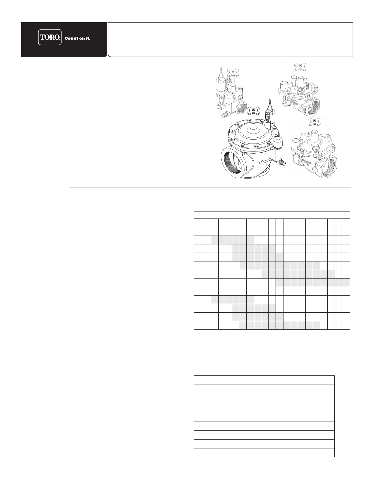
Built on proven technologies and components, the Toro 220 Series
brass valves are tough, have excellent performance and are
extremely reliable. A self-flushing, clog-resistant, stainless-steel filter
for dirty water conditions assures years of trouble-free performance.
In commercial installations, it is advantageous to install the valves in
a valve box. This enables the valve to be located, accessed and
maintained easily. The use of clean aggregate in the bottom of the
box, and keeping valve box locations away from structures, potential
hardscaping features (such as sidewalks) and large planting
locations is recommended. Additionally, valve box locations generally
should be in shrub beds and at right angles to structure locations.
If the valves are installed below grade without a valve box, access to
the top of the valve should be provided using a section of 4" PVC
pipe and a Toro Valve Cover (Part No. 850-00) installed directly over
each valve.
Specifications
Models:
❚ 220 Series electric - 1", 1
1
⁄4", 11⁄2", 2", 21⁄2", 3”
❚ 220 Series hydraulic - 1", 1
1
⁄2", 2"
■ Flow range:
❚ 1" - 5—40 GPM
❚ 1
1
⁄4" - 20—100 GPM
❚ 1
1
⁄2" - 20—130 GPM
❚ 2" - 30—180 GPM
❚ 2
1
⁄2" - 60—250 GPM
❚ 3" - 80—350 GPM
■ Operating pressure:
❚ 10—220 psi maximum
❚ Pressure-regulating models:
– Outlet: 5-30 psi, ±3 psi (EZR-30)
5-100 psi, ± 3 psi (EZR-100)
– Inlet: 15-220 psi
■ Minimum inlet/outlet pressure differential: 10 psi
■ Burst pressure safety rating: 750 psi
■ Body styles:
❚ Globe - 1", 1
1
⁄4", 11⁄2", 2" female threads, NPT and BSP
❚ Angle - 2
1
⁄2", 3" female threads, NPT and BSP
■ Solenoid: 24 V a.c.
❚ Inrush: 0.40 amps, 11.50 VA
❚ Holding: 0.20 amps, 5.75 VA
■ Dimensions:
❚ 1" — 5
3
⁄4" H x 5" W
❚ 1
1
⁄4" — 61⁄2" H x 6" W
❚ 1
1
⁄2" — 61⁄2" H x 6" W
❚ 2" — 7
1
⁄2" H x 5" W
❚ 2
1
⁄2" — 83⁄4" H x 81⁄2" W
❚ 3" — 8
3
⁄4" H x 81⁄2" W
■ Ingot brass and stainless-steel construction
■ Removable, self-flushing, contamination-proof, 120-mesh,
stainless-steel filter screen (electric models)
■ Manual flow control: adjustable to zero flow
■ Bleed screw (electric models): bleeds internally downstream
■ Pressure-regulating models:
❚ Precise pressure control with compact EZReg dial design
❚ Pressure regulates in electric and manual modes,
serviceable under pressure
❚ Schrader-type valve for pressure gauge attachment
220 Series Brass Valve
Installation and Operating Instructions
Table 2 — Voltage Requirement (standard solenoid)
Voltage Inlet Pressure
22.5 V a.c. 220 psi
21.1 V a.c. 200 psi
20.2 V a.c. 175 psi
19.1 V a.c. 150 psi
18.2 V a.c. 125 psi
17.1 V a.c. 100 psi
16.1 V a.c. 75 psi
16.0 V a.c. 50 psi
Note: For optimum performance, calculate total friction loss to
ensure sufficient downstream pressure. Values shown in psi.
Table 1 — Friction Loss Data
GPM Flow
Model 5 10 15 20 30 40 50 60 70 80 100 120 150 170 180 200 250 300 350
Electric
1" 2.0 2.5 1.5 2.5 5.5 7.0
11⁄4" 4.4 4.7 5.1 5.5 5.8 7.2
11⁄2" 3.9 4.2 4.6 4.9 5.2 5.5 7.2
2" 1.0 2.0 2.0 2.5 3.0 3.5 6.0 7.5 10.0 12.0 14.0
21⁄2" 2.0 2.2 2.3 2.4 2.5 3.0 4.0 4.5 5.5 7.0
3" 2.2 2.4 2.5 3.0 4.0 4.5 5.5 6.5 7.0 7.5
Hydraulic
1" <1 <1 1.5 2.5 5.5 7.0
11⁄4" 2.0 2.7 3.7 4.8 6.0 8.0
11⁄2" <1 1.5 2.5 3.0 4.5 5.0 8.0
2" <1 1.0 1.1 1.5 2.5 3.0 5.5 7.0 10.0 11.5 14.5

Installation Guidelines
• Note the flow direction arrow in the side of the valve body and install accordingly.
• The valve can be installed at any angle without affecting operation.
Electric valves only:
• Use direct-burial irrigation control wire for connection from the controller to valves.
• Leaving a wire expansion loop at each valve location on long-run wire lengths is recommended.
• Waterproof wire splice connectors are absolutely essential for proper electric control system operation. Follow the
installation instructions provided with the connectors for optimum waterproof splice protection.
Hydraulic valves only:
Note:
The normally open hydraulic valve is particularly appropriate for dirty-water applications such as effluent water use.
With these valves, the main-flow water supply is not utilized as a source for closing the valve. The pressure within the
diaphragm chamber on a normally open valve is supplied separately through a filtered water source from the controller.
• To enable proper valve operation, the filtered water supplied to the controller and valves must be obtained from the highest source of pressure within the irrigation system. In other words, the water pressure in the control tubing from the controller to the valves must be greater than or equal to the main-flow water pressure on the inlet side of the valve
• The recommended maximum control tubing run is 1000'. Exceeding this distance may cause erratic valve operation.
• Prior to connecting the control tube to the valve fitting, the tube must be pre-filled and completely free of all debris and
trapped air. A flushing adapter (model 995-02) enables the tubing to be easily attached to a standard water hose end for
this procedure.
• Leaving an expansion loop at each valve location is recommended.
• Hydraulic valve control tubing should be rated for a maximum continuous working pressure of 220 psi with
1
⁄4" O.D. and 1⁄8"
I.D. Toro polyethylene control tubing and fittings are recommended for this type of installation. See Table 3 below.
Valve Operation and Adjustment
Flow Control
The flow control is used to reduce the flow and pressure to the valve outlet. By turning the control handle clockwise, the flow
will gradually be reduced to zero.
• For valve models
without EZReg, adjust the flow control as necessary for optimum sprinkler performance.
• For valve models
with EZReg, the flow control should remain in the fully open position. Use only for emergency shut off.
Manual Bleed Knob (electric valves only)
The manual bleed knob is used to manually operate the valve. Turning the knob counterclockwise 2–3 turns allows water to
bleed downstream from the diaphragm chamber, relieving pressure from the top of the diaphragm which allows the valve to
open. Turning the bleed knob clockwise until finger tight, shuts off the discharge enabling pressure to build within the
diaphragm chamber, causing the valve to close.
Pressure Regulation (electric valves with EZReg only)
An accurate, adjustable dial coupled with a forward-flow valve design allows the 220 series valve with EZReg to regulate
downstream water pressure with precision. It can regulate accurately down to 5 GPM flow (1" model) and only requires 10 psi
differential pressure to operate. The EZReg will operate during electrical and manual valve operation.
To adjust, remove the cover from the regulator dial. Turn the dial until the pointer is on the desired downstream pressure:
5–30 psi (EZR-30) or 5–100 psi (EZR-100).
Note: Due to the micro-adjustment feature of the EZReg, the dial requires several complete revolutions to move the pointer
from the minimum to the maximum adjustment settings.
Operate the valve (electrically or manually). Check the flow control to confirm that it is in the fully open position. Adjust the
regulator dial if necessary for optimum sprinkler operation.
To confirm the downstream pressure using a pressure gauge, remove the cap from the Schrader-type valve located directly
below the EZReg. Attach a Toro pressure gauge (Model 995-51) to the Schrader-type valve for a direct reading. Adjust EZReg
dial as necessary for the desired pressure.
Note: The valve will remain operational if removal of the EZReg assembly is required.
Table 3 — 1/4" Control Tubing and Accessories
(2000' Coil, 1⁄4" x 1⁄8" Hard Reel)
Model 900-11 - Blue on Black color code
Model 900-12 - Yellow on Black color code
Model 900-13 - Pink on Black color code
Model 900-14 - White on Black color code
Model 900-21 - Adapter, compression to poly 1⁄4" to 1⁄4"
Model 900-24 - Adapter, 1⁄8" Male NPT to 1⁄4" poly
Model 900-30 - Metal Coupler, 1⁄4" to 1⁄4"
Model 900-40 - Retainer, 1⁄4"
Model 900-50 - Metal Tee 1⁄4" x 1⁄4" x 1⁄4"
Model 900-70 - Tubing Plug, 1⁄4"
© 2003 The Toro Company, Irrigation Division • An ISO 9000-certified Company Form Number 373-0027 Rev. B
 Loading...