

Page 1

Recycler
Walk-Behind Power Mower
Model No.: 20651–9900001 & Up
FORM NO. 3322–298
Operator’s Manual
International English (GB)
Page 2
Contents
Introduction
Page
Introduction 2.
Safety 3
Symbol Glossary4. . . . . . . . . . . . . . . . . . . . . . . . . .
Assembly 7
Before Starting7. . . . . . . . . . . . . . . . . . . . . . . . . . . . . . .
Oil 7
Gasoline 8
Operation 9
Starting the Engine9. . . . . . . . . . . . . . . . . . . . . . . . .
Stopping the Engine9. . . . . . . . . . . . . . . . . . . . . . . .
Self–propel Drive10. . . . . . . . . . . . . . . . . . . . . . . . . .
Adjusting the Cutting Height10. . . . . . . . . . . . . . . . .
Operating T
Changing the Handle Height11. . . . . . . . . . . . . . . . .
Maintenance 12
Recommended Maintenance Schedule12. . . . . . . . .
Air Filter13. . . . . . . . . . . . . . . . . . . . . . . . . . . . . . . . .
Draining Gasoline13. . . . . . . . . . . . . . . . . . . . . . . . .
Change Engine Oil13. . . . . . . . . . . . . . . . . . . . . . . . .
Spark Plug14. . . . . . . . . . . . . . . . . . . . . . . . . . . . . . .
Adjusting the Self-propel Cable14. . . . . . . . . . . . . . .
Maintaining the Blade15. . . . . . . . . . . . . . . . . . . . . .
Lubricating the Self–propel Drive16. . . . . . . . . . . . .
Cleaning the Underside of the Mower Housing17. . .
Cleaning Under the Belt Cover17. . . . . . . . . . . . . . .
Troubleshooting 18
Storage 19
Fuel 19
Preparing the Engine19. . . . . . . . . . . . . . . . . . . . . . .
Cleaning the Mower19. . . . . . . . . . . . . . . . . . . . . . . .
General 19
Folding the Handle19. . . . . . . . . . . . . . . . . . . . . . . . .
Removing From Storage20. . . . . . . . . . . . . . . . . . . .
Accessories 20
Rear Grass Catcher20. . . . . . . . . . . . . . . . . . . . . . . . .
Side Dischar
. . . . . . . . . . . . . . . . . . . . . . . . . . . . . . . .
. . . . . . . . . . . . . . . . . . . . . . . . . . . . . . . . . . . . . .
. . . . . . . . . . . . . . . . . . . . . . . . . . . . . . . . . . .
. . . . . . . . . . . . . . . . . . . . . . . . . . . . . . . . . . . . . .
. . . . . . . . . . . . . . . . . . . . . . . . . . . . . . . . .
. . . . . . . . . . . . . . . . . . . . . . . . . . . . . . . . . . .
ips 10
. . . . . . . . . . . . . . . . . . . . . . . . . . . .
. . . . . . . . . . . . . . . . . . . . . . . . . . . . . . . . .
. . . . . . . . . . . . . . . . . . . . . . . . . . . . . .
. . . . . . . . . . . . . . . . . . . . . . . . . . . . . . . . . . . . .
. . . . . . . . . . . . . . . . . . . . . . . . . . . . . . . . . . . . .
. . . . . . . . . . . . . . . . . . . . . . . . . . . . . . . . . .
. . . . . . . . . . . . . . . . . . . . . . . . . . . . . . . . .
ge Chute23. . . . . . . . . . . . . . . . . . . . . . .
Thank you for purchasing a T
All of us at T
your new product, so feel free to contact your local
Authorized Service Dealer for help with service, genuine
T
oro parts, or other information you may require.
Whenever you contact your Authorized Service Dealer or
the factory
your product. These numbers will help the Service Dealer
or Service Representative provide exact information about
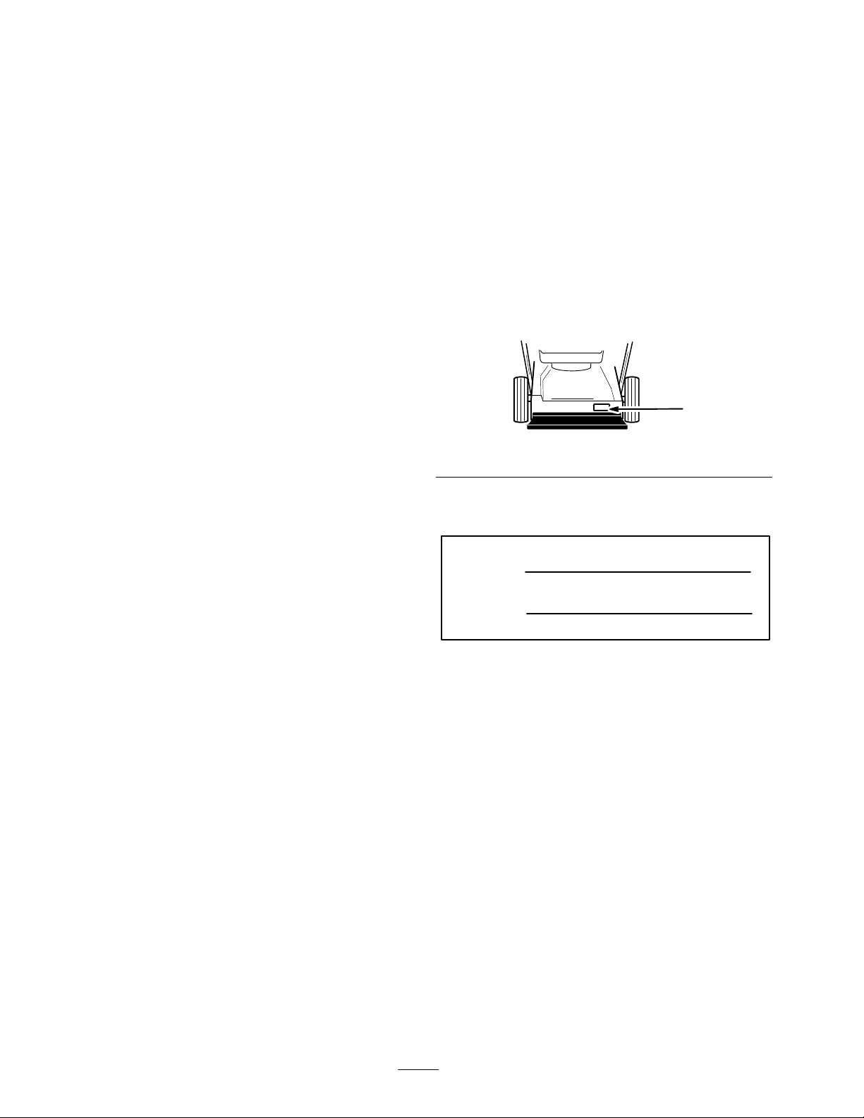
your specific product. Y
number decal located in a unique place on the product as
shown below
1. Model
For
your convenience, write the product model and serial
numbers in the space below
Model No:
Serial No.
Read
this manual carefully to learn how to operate and
maintain your product correctly
help you and others avoid personal injury and damage to
the product. Although T
safe, state-of-the-art products, you are responsible for
using the product properly and safely
responsible for training persons who you allow to use the
product about safe operation.
The T
potential hazards and has special safety messages that help
you and others avoid personal injury
DANGER, W
used to identify the level of hazard. However
of the hazard, be extremely careful.
oro want you to be completely satisfied with
, always know the model and serial numbers of
.
and Serial Number Decal
oro warning system in this manual identifies
ARNING and CAUTION are signal words
oro product.
ou will find the model and serial
1064
.
. Reading this manual will
oro designs, produces and markets
. Y
ou are also
, even death.
, regardless
EThe T
oro Company
All Rights Reserved
– 1998
DANGER
serious injury or death if the recommended precautions
are not followed.
WARNING
or death if the recommended precautions are not followed.
signals an extreme hazard that will cause
signals a hazard that may cause serious injury
2
Printed in USA
Page 3

CAUTION
moderate injury if the recommended precautions are not
followed.
wo other words are also used to highlight information.
T
“Important” calls attention to special mechanical
information and “Note” emphasizes general information
worthy of special attention.
signals a hazard that may cause minor or
•
Before using, always visually inspect to see that the
blades, blade bolts, and cutter assembly are not worn
or damaged. Replace worn or damaged blades and
bolts in sets to preserve balance.
•
On multi–bladed machines, take care as rotating one
blade can cause other blades to rotate.
The left and right side of the machine is determined by
standing behind the handle in the normal operator
position.
’s
Safety
Training
•
Read the instructions carefully
controls and the proper use of the equipment.
•
Never allow children or people unfamiliar with these
instructions to use the lawnmower
may restrict the age of the operator
Never mow while people, especially children, or pets
•
are nearby
Keep in mind that the operator or user is responsible
•
for accidents or hazards occurring to other people or
their property
.
.
Preparation
•
While mowing, always wear substantial footwear and
long trousers. Do not operate the equipment when
barefoot or wearing open sandals.
•
Thoroughly inspect the area where the equipment is to
be used and remove all objects which may be thrown
by the machine.
• W
ARNING – Gasoline is highly flammable.
•
Store fuel in containers specifically designed for
this purpose.
•
Refuel outdoors only and do not smoke while
refuelling.
. Be familiar with the
. Local regulations
.
Operation
•
Do not operate the engine in a confined space where
dangerous carbon monoxide fumes can collect.
•
Mow only in daylight or in good artificial light.
• A
void operating the equipment in wet grass, where
feasible.
Always be sure of your footing on slopes.
•
• W
alk, never run.
•
For wheeled rotary machines, mow across the face of
slopes, never up and down.
•
Exercise extreme caution when changing direction on
slopes.
Do not mow excessively steep slopes.
•
•
Use extreme caution when reversing or pulling the
lawnmower towards you.
•
Stop the blade(s) if the lawnmower has to be tilted for
transportation when crossing surfaces other than grass,
and when transporting the lawnmower to and from the
area to be mowed.
•
Never operate the lawnmower with defective guards or
shields, or without safety devices, for example
deflectors and/or grass catchers, in place.
•
Do not change the engine governor settings or
overspeed the engine.
•
Disengage all blade and drive clutches before starting
the engine.
•
Start the engine or switch on the motor carefully
according to instructions and with feet well away from
the blade(s).
Add fuel before starting the engine. Never remove
•
the cap of the fuel tank or add gasoline while the
engine is running or when the engine is hot.
•
If fuel is spilled, do not attempt to start the engine
but move the machine away from the area of
spillage and avoid creating any source of ignition
until petrol vapors have dissipated.
•
Replace all fuel tanks and container caps securely
Replace faulty silencers.
•
•
Do not tilt the lawnmower when starting the engine or
switching on the motor
to be tilted for starting. In this case, do not tilt it more
than absolutely necessary and lift only the part which
is away from the operator
Do not start the engine when standing in front of the
•
dischar
ge chute.
•
.
Do not put hands or feet near or under rotating parts.
Keep clear of the dischar
•
Never pick up or carry a lawnmower while the engine
is running.
, except if the lawnmower has
.
ge opening at all times.
3
Page 4
•
Stop the engine and disconnect the spark plug wire:
•
before clearing blockages or unclogging chute
•
before checking, cleaning or working on the
lawnmower
after striking a foreign object. Inspect the
•
lawnmower for damage and make repairs before
restarting and operating the lawnmower
•
if lawnmower starts to vibrate abnormally (check
immediately)
Stop the engine
•
•
whenever you leave the lawnmower;
•
before refuelling.
•
Reduce the throttle setting during engine shut down
and, if the engine is provided with a shut-of
turn the fuel of
f at the conclusion of mowing.
f valve,
•
Allow the engine to cool before storing in any
enclosure.
o reduce the fire hazard, keep the engine, silencer
• T
battery compartment and petrol storage area free of
grass, leaves, or excessive grease.
•
Check the grass catcher frequently for wear or
deterioration.
Replace worn or damaged parts for safety
•
If the fuel tank has to be drained, this should be done
•
outdoors.
.
,
Sound Pressure Level
This
unit has a sound pressure at the operator’s ear of 85
dB(A), based on measurements of identical machines per
Directive 81/1051/EEC.
•
Go slow when using a trailing seat.
Maintenance and storage
• Keep
•
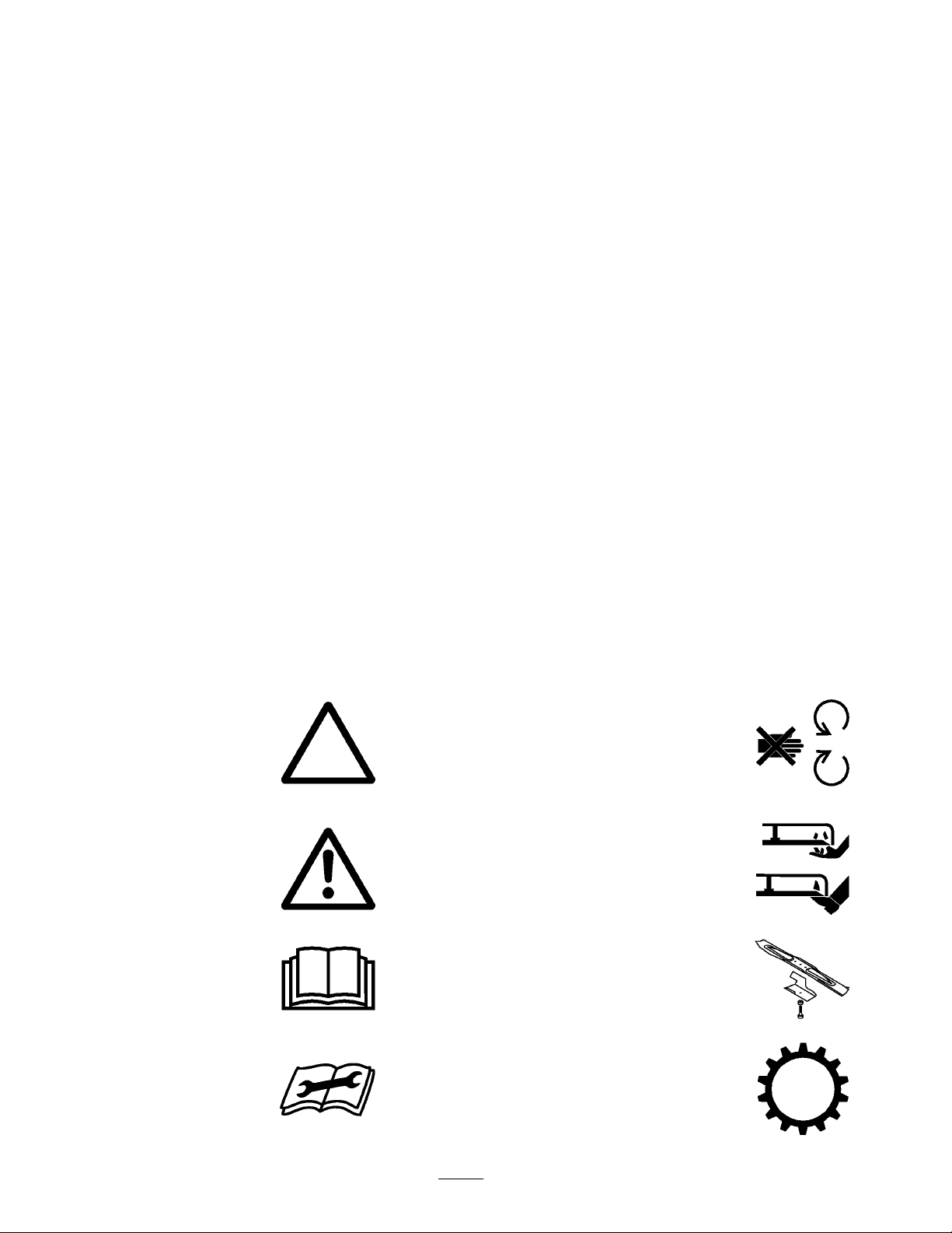
Symbol
Safety
symbol within triangle
indicates a hazard.
Safety alert symbol
all nuts, bolts and screws tight to be sure the
equipment is in safe working condition.
Never store the equipment with petrol in the tank
inside a building where fumes may reach an open
flame or spark.
Glossary
alert triangle —
Sound Power Level
This
unit has a sound power level of 100 LwA, based on
measurements of identical machines per Directive
84/538/EEC.
Vibration Level
This
unit has a maximum hand-arm vibration level of 8.0
m/s2, based on measurements of identical machines per
EN 1033.
Do not open or
remove safety shields
while engine is
running.
Rotating blade can cut
off toes or fingers.
Stay clear of mower
blade as long as
engine is running.
Read operator
manual.
Consult technical
manual for proper
service procedures.
’s
To avoid blade failure
when mulching, use
blade stiffener when
mower is equipped
with mulching plug.
Transmission
4
Page 5
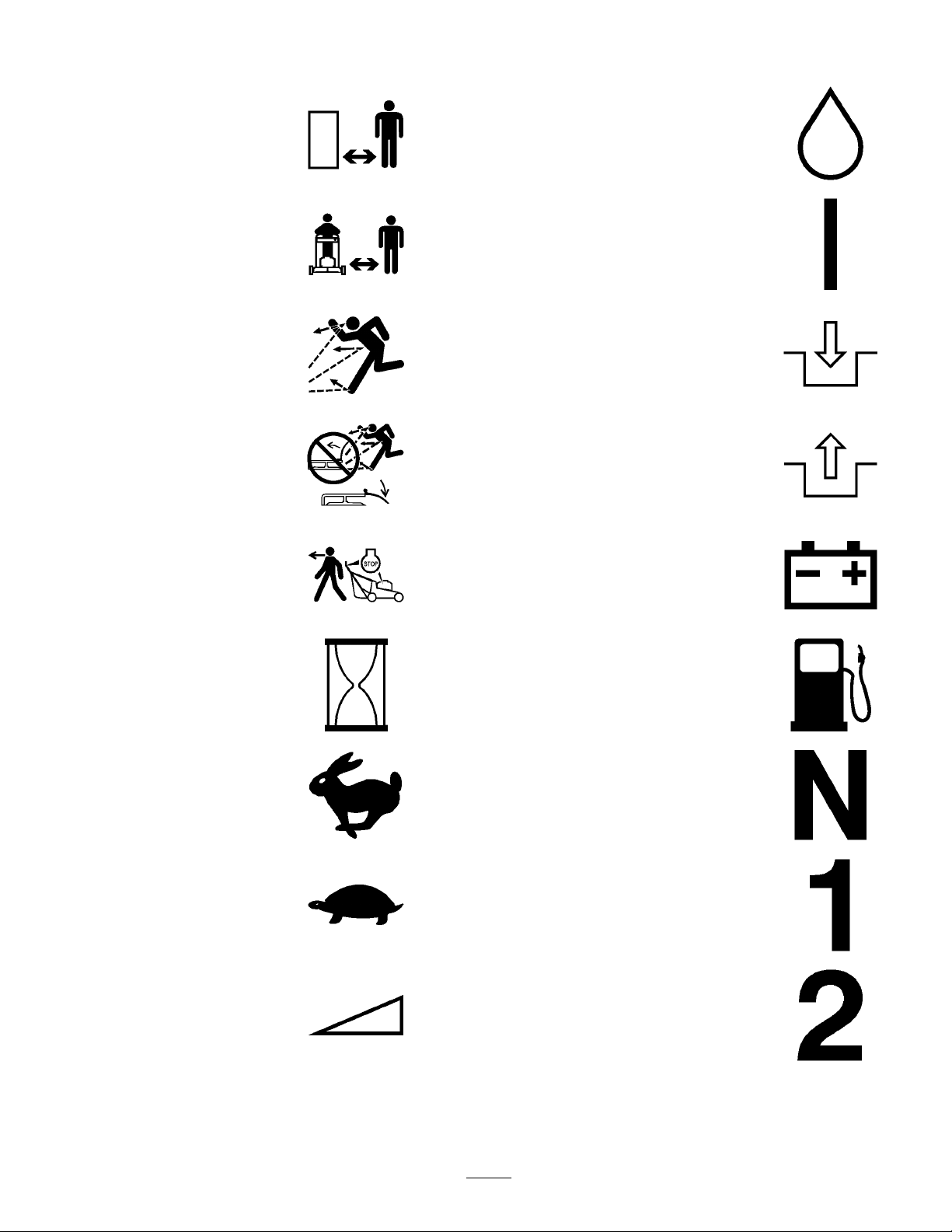
Stay a safe distance
from the machine.
Oil
Stay a safe distance
from the mower
Thrown or flying
objects — Whole body
exposure
Thrown or flying
objects — Rotary
side-mounted mower
Keep deflector shield
in place.
Stop engine before
leaving operator
position.
Hourmeter/elapsed
operating hours
.
On/Run
Engage
.
Disengage
Battery charging
condition
Fuel
Fast Neutral
Slow
Decreasing/Increasing
First gear
Second gear
5
Page 6

Grease lubrication
point
Third gear
Engine start
Engine stop
Choke
Primer (start aid)
Push primer three
times.
Cutting element —
basic symbol
Cutting element —
height adjustment
Pull rope.
Wheel
Wheel traction
Properly dispose of
batteries.
Insert key into ignition
switch.
Turn key in ignition
switch.
Lower control bar
Raise control bar
Raise/lower control
bar.
.
.
6
Page 7
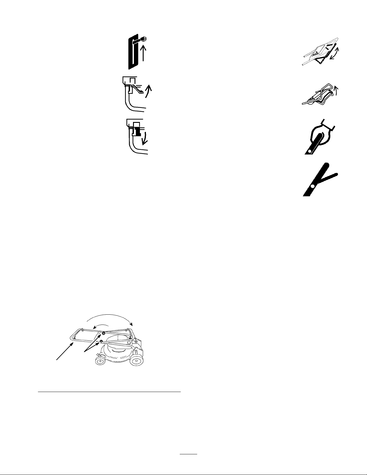
Move control.
Raise/lower control
bar.
Move control forward.
Move control
rearward.
Assembly
1. Loosen
Note:
cables.
2. T
the handle knobs and lift the top handle half in
an arc until the handle halves are in line and nest
together (Fig. 1).
Use care to prevent pinching or stretching the
ighten the knobs securely
.
Raise control bar
Raise control bar
Lower control bar
Before
Starting
.
.
.
Oil
Initially,
(0.6 liters) of SAE 30 oil; 10W
if SAE 30 is not available. Use any high quality deter
oil having the American Petroleum Institute (API)
“service classification”—SF
the crankcase must be filled with 20 ounces
-30 oil may be substituted
, SG, SH or SJ.
gent
Rotate the handle toward rear of the mower until it
3.
snaps into the handle brackets (Fig. 1).
1
2
Figure
1. Knob 2. Top
1
handle half
1679
Before each use, ensure that the oil level is between the
FULL and ADD marks on the dipstick (Fig. 2). Add oil if
the level is low
Position the mower on a level surface and clean
1.
around the dipstick (Fig. 2).
2.
Remove the dipstick by rotating the cap
counterclockwise 1/4 turn.
3. W
ipe the dipstick clean.
4.
Insert the dipstick into the filler neck and rotate the
cap clockwise 1/4 turn.
5.
Remove the dipstick and check the level of the oil on
the side of the dipstick with the FULL and ADD marks
(Fig. 2).
7
.
Page 8
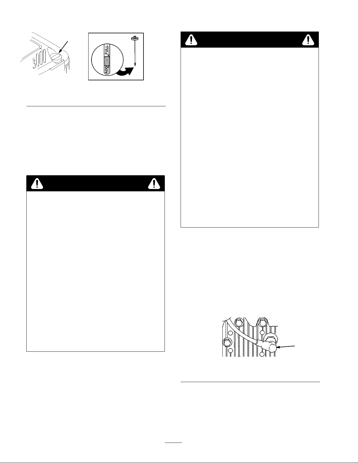
1
1626
Figure
1. Dipstick
6. If
the level is low
the FULL mark on the dipstick.
IMPORTANT
because the engine could be damaged when started.
Pour the oil slowly
, add enough oil to raise the level to
: Do not fill above the FULL mark
.
2
Gasoline
DANGER
POTENTIAL HAZARD
•
In certain conditions gasoline is extr
flammable and highly explosive.
WHA
T CAN HAPPEN
•
A fir
e or explosion fr
and others and cause pr
HOW T
•
•
•
• Stor
•
O AVOID THE HAZARD
Use a funnel and fill the fuel tank outdoors, in
an open ar
any gasoline that spills.
Do not fill the fuel tank completely full. Add
gasoline to the fuel tank until the level is 1/4” to
1/2” (6 mm to 13 mm) below the bottom of the
filler neck. This empty space in the tank allows
gasoline to expand.
Never smoke when handling gasoline, and stay
away fr
fumes may be ignited by a spark.
keep it out of the r
Never buy mor
gasoline.
ea, when the engine is cold. W
om an open flame or wher
e gasoline in an appr
om gasoline can burn you
operty damage.
oved container and
each of childr
e than a 30-day supply of
emely
ipe up
e gasoline
en.
DANGER
POTENTIAL HAZARD
•
When fueling, under certain cir
static charge can develop, igniting the gasoline.
WHA
T CAN HAPPEN
•
A fir
e or explosion fr
and others and cause pr
HOW T
•
•
•
•
•
Do not use gasoline that has been stored from one season
to the next. Use fresh, clean,
gasoline. Unleaded gasoline burns cleaner
life, and promotes good starting. Leaded gasoline can be
used if unleaded is not available.
T
oro also recommends that T
used regularly during operation and storage. T
Stabilizer/Conditioner cleans the engine during operation
and prevents gum-like varnish deposits from forming
during periods of storage.
1.
O AVOID THE HAZARD
Always place gasoline containers on the gr
away from your vehicle befor
Do not fill gasoline containers inside a vehicle
or on a truck or trailer bed because interior
carpets or plastic truck bed liners may insulate
the container and slow the loss of any static
charge.
When practical, r
equipment fr
the equipment with its wheels on the r
If this is not possible, then refuel such
equipment on a truck or trailer fr
container
dispenser nozzle.
If a gasoline dispenser nozzle must be used,
keep the nozzle in contact with the rim of the
fuel tank or container opening at all times until
fueling is complete.
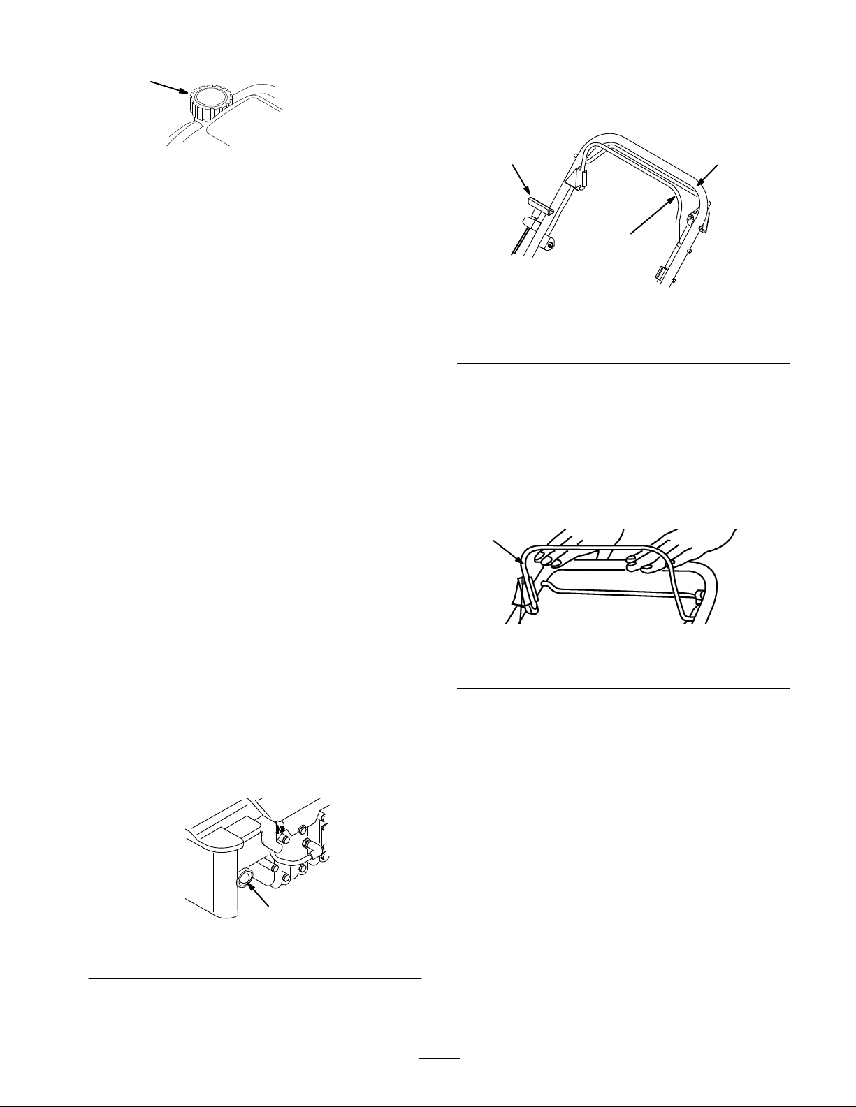
Pull the wire off of the spark plug (Fig. 3).
om the truck or trailer and r
, rather than fr
om gasoline can burn you
operty damage.
emove gas–power
unleaded
oro Stabilizer/Conditioner be
cumstances, a
ound
e filling.
ed
efuel
ound.
om a portable
om a gasoline
regular grade
, extends engine
oro
1
1. Spark
2. Clean
plug wire
from the tank (Fig. 4).
8
Figure
around the fuel tank cap and remove the cap
3
1002
Page 9
3.
1
Pull the starter handle lightly until resistance is felt,
then pull it sharply (Fig. 6). Allow the rope return to
the handle slowly
.
Figure
1. Fuel
tank cap
3. Using
IMPORTANT
fr
om the top of the tank because the gasoline must have
r
oom to expand.
4.
IMPORTANT
use methanol, gasoline containing methanol, gasohol
containing mor
because the fuel system could be damaged.
Do not use fuel additives other than those
manufactur
such as Toro Stabilizer/Conditioner
Stabilizer/Conditioner is a petr
pr
alcohol base such as ethanol, methanol, or isopr
Do not use additives to enhance the power or
performance of the engine.
unleaded gasoline, fill the fuel tank to within
1/4” to 1/2” (6 to 13 mm) from top of tank, not into
filler neck.
: Do not fill the tank mor
Install the fuel tank cap and wipe up any spilled fuel.
: Do not mix oil with the gasoline. Never
e than 10% ethanol, or white gas
ed for fuel stabilization during storage,
oduct. Toro does not r
4
e than 1/4”
. T
oro
oleum distillate based
ecommend stabilizers with an
opyl.
1626
3 2
1
m-3712
Figure
6
1. Blade
2.
Note:
repeat steps 1–3.
Stopping
1. Release
control bail
Upper handle
If the engine fails to start after three (3) pulls,
3.
Starter handle
the Engine
the blade control bail (Fig. 7). Both the engine
and blade will stop. See your dealer immediately if
they do not.
5.
Connect the spark plug wire (Fig. 3).
Operation
Starting
1. Push
temperature is 13
seconds between each push (Fig. 5).
IMPORTANT
warm engine.
1. Primer
the Engine
the primer three times (five times if the
_C/55_
F or below), waiting 2
: Do not use the primer to r
Figure
1
5
estart a
m-3855
1. Blade
control bail
Figure
1060
7
2. Hold
(Fig. 6).
the blade control bail against the upper handle
9
Page 10
Self–propel
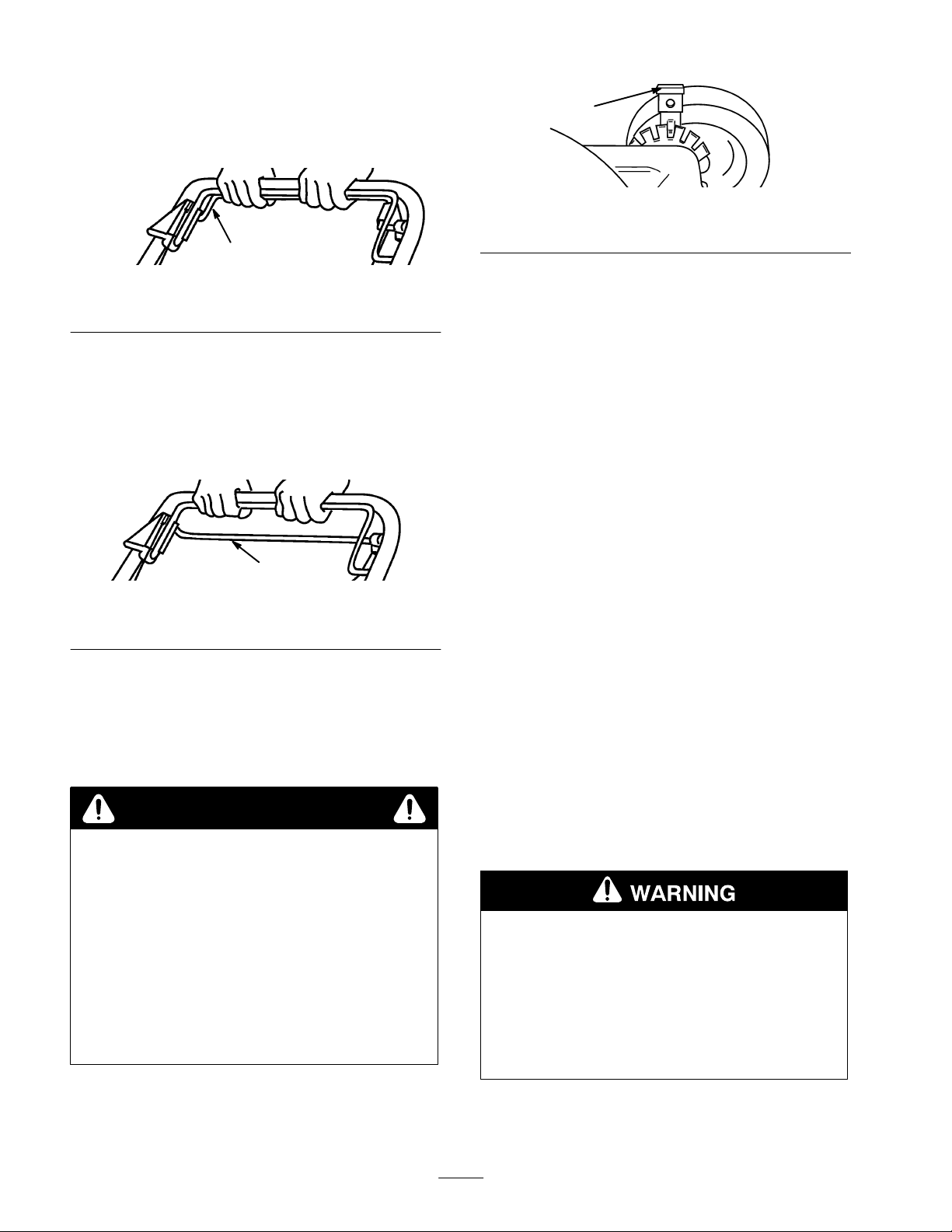
1. To
operate the self-propel drive, squeeze the
self-propel bail against the handle and hold it (Fig. 8).
1. Self-propel
Note:
reduce ground speed, increase the space between the bail
and the handle.
2. T
o disengage the self-propel drive, release the
self-propel bail (Fig. 9), then push the mower forward
manually at least 1 in.
bail
Maximum self-propel ground speed is fixed. T
Drive
1
Figure
8
o
1017
1
Figure
10
1. Wheel
2. Release
Note:
height adjustment lever
the height adjust lever and seat it securely in
the notch.
Set all four (4) wheels at the same height.
Operating Tips
General Tips
• Review
carefully before operating the mower
Clear the area of sticks, stones, wire, branches, and
•
other debris which could be picked up or hit by the
blade and become thrown objects.
the safety instructions and read this manual
.
1021
1
Figure
1. Self-propel
Adjusting
Each
wheel is adjusted individually with a wheel height
adjustment lever
and 3-1/2 inches (25, 38, 51, 64, 74 and 86 mm).
bail
the Cutting Height
. Cutting heights are 1, 1-1/2, 2, 2-1/2, 3
9
DANGER
POTENTIAL HAZARD
•
Adjusting the height-of-cut levers could bring
your hands into contact with the moving blade.
WHA
T CAN HAPPEN
•
Contact with a r
injury.
HOW T
•
•
O AVOID THE HAZARD
Stop the engine and wait for all movement to
stop befor
Do not put your fingers under the mower
housing when adjusting the height-of-cut.
otating blade can cause serious
e adjusting the cutting height.
1016
•
Keep everyone, especially children and pets, away
from the area of operation.
• A
void striking trees, walls, curbs, or other solid
objects. Never deliberately mow over any object.
•
If an object is struck, or the mower starts to vibrate,
immediately stop the engine, disconnect the spark plug
wire, and examine the mower for damage.
•
Maintain a
Periodically file down nicks on blade.
•
Replace the blade when necessary with an original
T
oro replacement blade.
•
Only mow dry grass or leaves. W
tend to clump on the yard and may cause the mower to
plug or the engine to stall. They may also be slippery
to walk on and could cause you to slip and fall.
POTENTIAL HAZARD
• W
et grass or leaves can cause you to slip and
contact the blade.
WHA
•
Blade contact can seriously injure you.
HOW T
•
Mow only in dry conditions.
sharp blade
T CAN HAPPEN
O AVOID THE HAZARD
throughout the cutting season.
et grass and leaves
1. T
o change the cutting height, pull the adjusting lever
toward the wheel and move it to the desired position
(Fig. 10).
10
•
Clean clippings or leaves from the underside of the
mower deck after each mowing.
Page 11
•
Keep the engine in good running condition.
•
Clean the air filter frequently
clippings and dust which clogs the air filter and
reduces engine performance.
. Mulching stirs up more
Changing
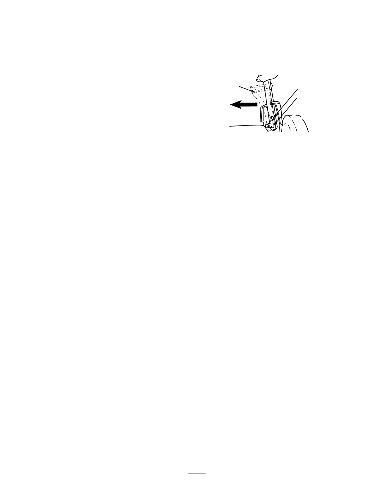
The
handle has two height positions—high and low
(Fig. 1
1). Select a handle height position that is most
comfortable for you.
the Handle Height
Cutting Grass
• In
the heat of Summer
inch height-of-cut settings. Only about
blade should be cut off. Cut below the 2 inch setting
only if the grass is sparse or it is Autumn when the
grass grows slowly
When cutting grass over six inches tall, mow using the
•
highest height-of-cut setting and a slower walking
speed; then mow again at a lower setting for best lawn
appearance. If the grass is too long, the mower may
plug and cause the engine to stall.
•
Alternate the mowing direction. This helps disperse
clippings over the lawn for even fertilization.
If the finished lawn appearance is unsatisfactory
or more of the following:
•
Sharpen the blade.
• W
alk at a slower pace while mowing.
•
Raise the height-of-cut setting on your mower
Cut grass more frequently
•
Overlap cutting swaths instead of cutting a full swath
•
with each pass.
, cut the grass at the 2, 2.5, or 3
!/3
of the grass
.
, try one
.
3
Figure
1. Low
setting
2.
High setting
1. Squeeze
of
2.
Position the handle and cable anchor over the pins at
the desired height.
Note:
.
slightly.
Adjust the cable. Refer to Adjusting the Self–propel
3.
Cable in the Maintenance section, page 14.
the bottom handle section (both sides) inward
f of the pins.
The belt cover may need to be loosened and moved
1
1
1
3.
Cable anchor
2
1026
•
Set the height-of-cut on the front wheels one notch
lower than the rear wheels. (example: set the front
wheels at the 2 inch setting and the rear wheels at the
2.5 inch setting)
Cutting Leaves
• When
•
• W
•
cutting is complete, ensure that 50% of the lawn
shows through the cut leaf cover
or more passes over the leaves.
Position all wheels at the same height-of-cut setting.
alk at a slower mowing speed if the leaves are not
being cut up finely enough to be hidden in the grass.
If you cut up a lot of oak leaves, add lime to your grass
in the spring. Lime reduces the acidity of the leaves.
. This may require one
11
Page 12
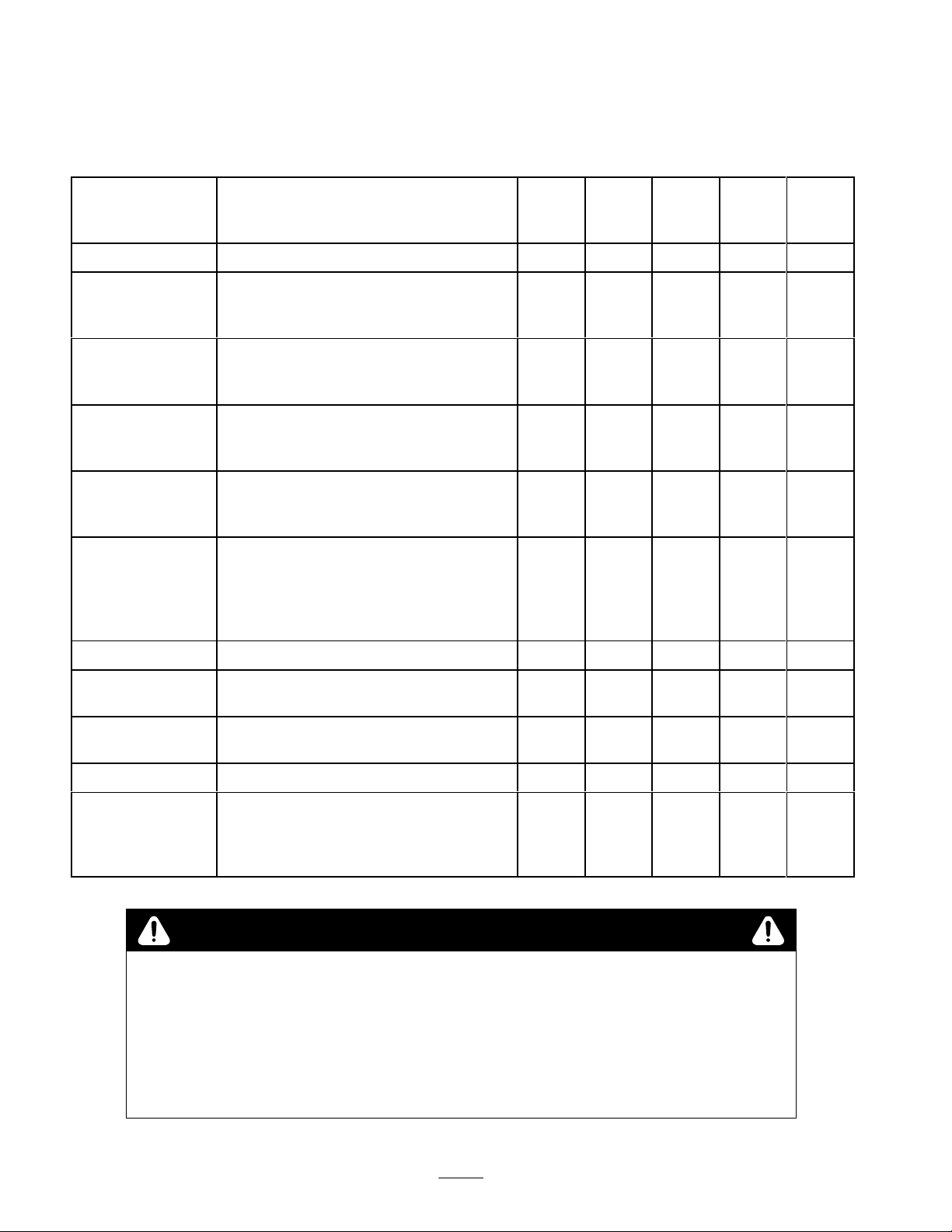
Maintenance
Recommended
Service
Housing
Fasteners
Air Filter
Engine Oil
Blade
Blade Brake
Item
Clean built-up grass clippings and dirt.
Check blade and engine mounting
fasteners. Keep all fasteners tight to keep
the mower in safe working condition.
Replace each mowing season or every
25 hours.
operating conditions are dusty.
Drain and refill engine crankcase with
fresh oil after first 5 hours of operation.
Thereafter
Sharpen or replace; maintain more
frequently if edge is dulled quickly in
rough or sandy conditions.
Check stopping time every 50 hours or at
the start of each mowing season. Blade
must stop within 3 seconds of releasing
bail; if not, see your Authorized T
Service Dealer for repair
Maintenance Schedule
Service Operation
Replace more frequently if
, change every 50 hours.
oro
.
After
every
use
X
5
Hours25Hours50Hours
X
X
X
X
X
100
Hours
Lubrication
Fuel System
Belt Cover
Spark Plug
Cooling System
POTENTIAL
•
If you leave the wir
WHA
T CAN HAPPEN
•
Accidental starting of engine could seriously injur
HOW T
•
Pull the wir
does not accidentally contact spark plug.
Grease rear height adjustor brackets.
Check for leakage and/or deterioration of
fuel hose. Replace if necessary
Remove and clean grass, clippings and
debris from under cover
Inspect and clean. Replace if necessary
Clean grass, clippings, debris or dirt that
may clog engine air cooling fins and
starter
. Clean more frequently if operated
under dirty or high chaf
.
f conditions.
CAUTION
HAZARD
e on the spark plug, someone could start the engine.
O AVOID THE HAZARD
e off of the spark plug befor
e you do any maintenance. Also push wir
X
.
. X
e you or other bystanders.
e aside so it
X
X
X
12
Page 13
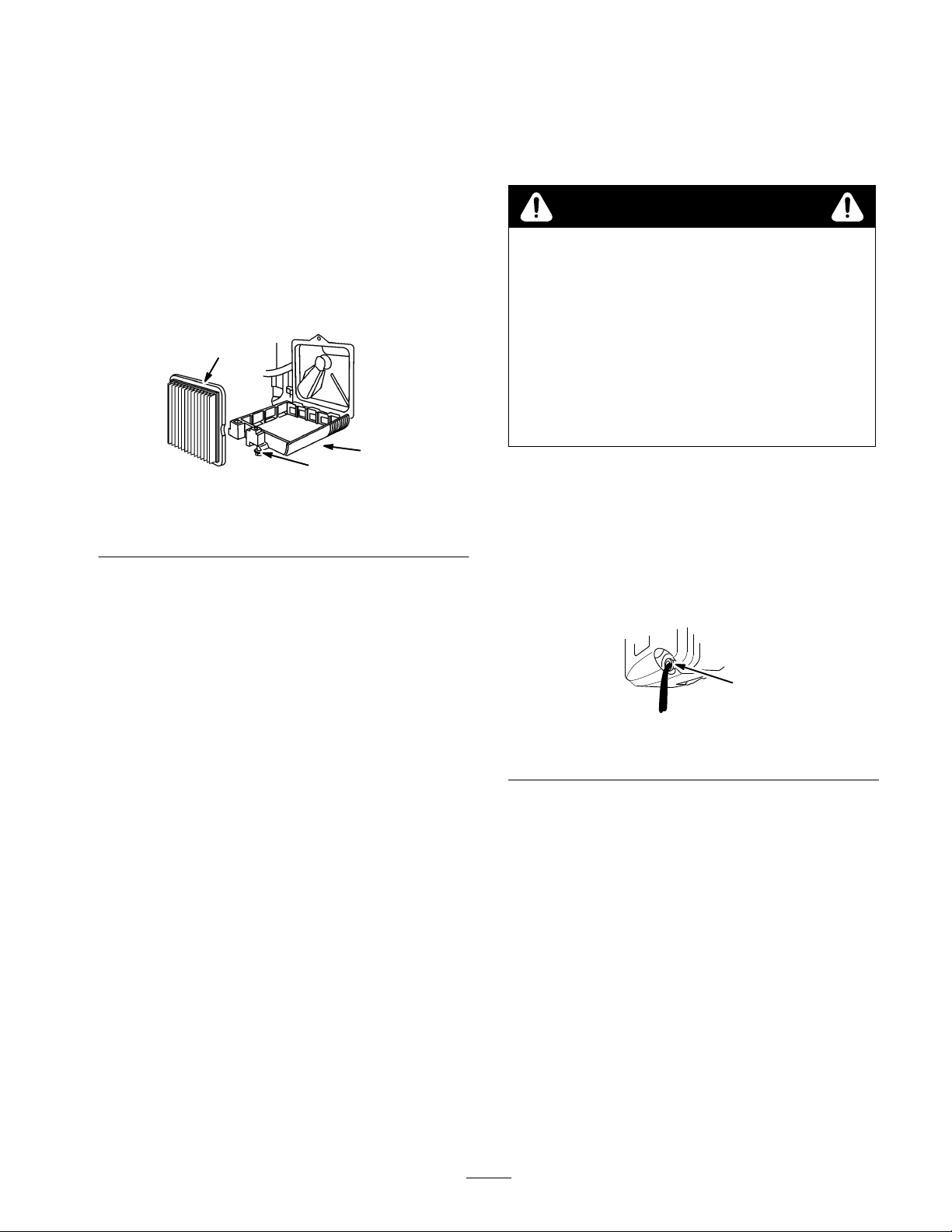
Air
Filter
Change
Engine Oil
Replace
replace it more frequently under dusty conditions.
IMPORTANT
air filter element; extr
1.
2.
3. T
1. Air
2. Screw
4. Remove
IMPORTANT
the air filter once every season or every 25 hours;
: Do not operate the engine without the
eme engine damage will occur
Stop the engine and pull the wire of
(Fig. 14).
Loosen the screw securing the air cleaner cover
(Fig. 12).
ilt the cover down and clean it thoroughly (Fig. 12).
1
Figure
filter
the paper air filter and discard it (Fig. 12).
: Do not try to clean a paper filter
f of the spark plug
3
2
12
3. Cover
1003
.
Change
and after 50 hours of operation thereafter
while the engine is warm.
.
the engine oil after the first 5 hours of operation
. Change oil
WARNING
POTENTIAL HAZARD
•
Gasoline is extr
explosive and under certain conditions can
cause personal injury or pr
WHA
T CAN HAPPEN
• T
ipping the mower may cause fuel leakage
fr
om the carbur
HOW T
• A
1.
2.
3.
4.
O AVOID THE HAZARD
void fuel spills by running the engine dry or
r
emoving gas with a hand pump; never siphon.
Drain the gasoline from the fuel tank. Refer to the
Draining Gasoline section, page 13.
Start the engine and let it run until it runs out of fuel.
Pull the wire off of the spark plug (Fig. 14).
Remove the dipstick and tip the mower on the left
side, draining the oil out the oil fill tube into an
appropriate container (Fig. 13).
emely flammable, highly
operty damage.
etor or fuel tank.
Insert a new paper air cleaner filter (Fig. 12).
5.
6.
Install the air cleaner cover and secure it with the
screw.
Draining
1. Stop
IMPORTANT
2.
3.
Note:
draining fuel.
the engine and wait for it to cool.
Pull the wire off of the spark plug (Fig. 14).
Remove the cap from the fuel tank and use a
pump-type syphon to drain the fuel into a clean gas
can.
This is the only procedure recommended for
Gasoline
: Drain gasoline fr
om a cold engine only
m–-1782
Figure
1. Oil
fill tube
.
5. Recycle
6. T
7.
Fill the crankcase to the FULL line on the dipstick
with fresh oil. Refer to the Oil section, page 7, for
specifications.
Check the oil level and install the dipstick.
8.
9. W
the oil as per local codes.
urn the mower upright.
ipe up any spilled oil.
13
13
Page 14
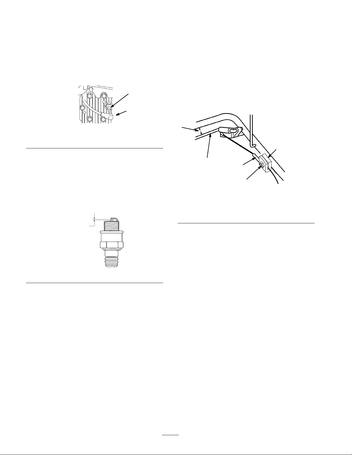
Spark
Use
Plug
a Champion RJ19LM spark plug or equivalent. The
correct air gap is 0.030” (0.76 mm). Remove the plug
after every 25 operating hours and check its condition.
1.
Stop the engine and pull the wire off the spark plug
(Fig. 14).
1
2
14
Figure
1. Spark
plug
2.
Spark plug wire
1004
Adjusting
Whenever
the handle height is changed, a new
the Self-propel Cable
self–propelled cable is installed, or the traction drive belt
slips, adjustment is required.
The self–propelled cable is adjusted on the handle by
moving the cable jacket held by the cable support.
1.
Loosen the nut on the cable support (Fig. 16).
2.
Hold the self–propel bail 1 to 1
!/2
in. (25 to 38 mm)
from the handle (Fig. 16).
1
4
2. Clean
around the spark plug and remove it from the
cylinder head.
IMPORTANT
spark plug. Do not clean the electr
damage could r
Set the gap on the new plug to 0.030” (0.76 mm) (Fig.
3.
: Replace a cracked, fouled, or dirty
odes because engine
esult fr
om grit entering the cylinder
15).
.030 in.
(.76 mm)
Figure
15
4. Install
5.
the spark plug and gasket seal. T
to 15 ft-lb (20 N
m).
Connect the spark plug wire (Fig. 14).
ighten the plug
2
3
.
1. 1
to 1
!/2
in. (25 to 38 mm)
2.
Self -propelled bail
3.
Cable jacket
986
3. Pull
4. T
5.
Note:
the cable jacket down (away from the bail).
ighten the nut on the cable support.
Release the bail and ensure that the cable is loose.
The cable must be loose with the bail in the
5
Figure
16
4.
Cable support
5. Nut
1063
released position or the mower may creep when the bail is
disengaged.
14
Page 15
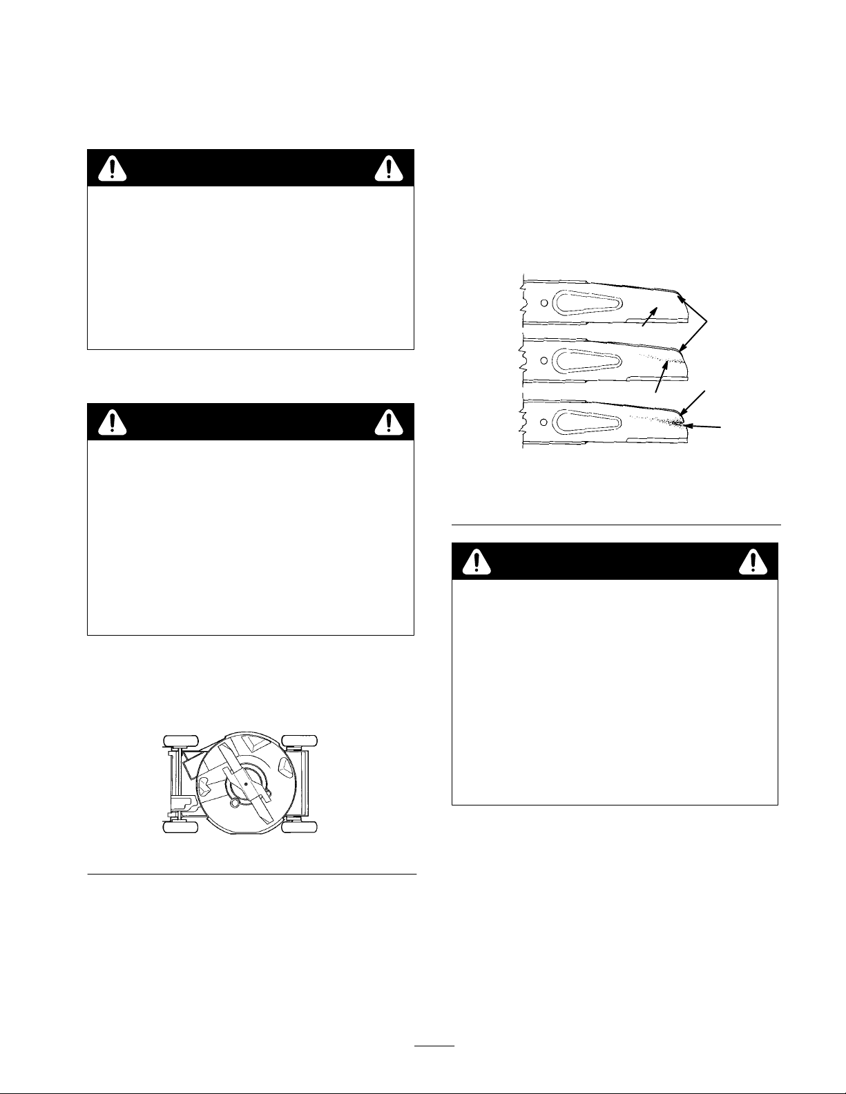
Maintaining
A
straight, sharp blade provides maximum cutting
performance. Regularly inspect and sharpen the blade.
the Blade
WARNING
POTENTIAL HAZARD
•
The blade is sharp.
WHA
T CAN HAPPEN
•
Contact with a sharp blade can cause serious
personal injury
HOW T
• W
O AVOID THE HAZARD
ear gloves or wrap the sharp edges of the
blade with a rag.
.
2.
Complete one of the following:
A.
If a slot or wear is noticed, (Fig. 18B & C), replace
the blade. Refer to the Removing and Installing the
Blade sections.
B.
If the blade is nicked or dull, sharpen it. Refer to
the Removing, Sharpening, Balancing, and
Installing the Blade sections.
C.
If there are no signs of wear of dullness, return the
mower to the upright position and replace the spark
plug wire (Fig. 14).
A
2
1
1.
Stop the engine and pull the wire of
(Fig. 14).
f of the spark plug
WARNING
POTENTIAL HAZARD
•
Gasoline is extr
explosive and under certain conditions can
cause personal injury or pr
WHA
T CAN HAPPEN
• T
ipping the mower may cause fuel leakage
fr
om the carbur
HOW T
• A
2.
3. T
O AVOID THE HAZARD
void fuel spills by running the engine dry or
r
emoving gas with a hand pump; never siphon.
Drain the gasoline from the fuel tank. Refer to the
Draining Gasoline section, page 13.
ip the mower on its left side (Fig. 17). A
the blade because starting problems may result.
emely flammable, highly
operty damage.
etor or fuel tank.
void rotating
B
3
C
18
3. Wear
4.
Slot formed
1. Sail
2. Flat
Figure
part of blade
DANGER
POTENTIAL
•
A worn or damaged blade could br
piece of the blade could be thr
operator’
WHA
T CAN HAPPEN
•
A thr
personal injury or death to the operator or
bystanders.
HOW T
•
Inspect the blade periodically for wear or
damage.
Replace a worn or damaged blade.
•
HAZARD
own into
s or bystander’s ar
own piece of the blade could cause serious
O AVOID THE HAZARD
ea.
1
4
270
eak and a
Figure
17
Inspecting the Blade
1. Examine
where flat and curved parts meet (Fig. 18A).
the blade for sharpness and wear
, especially
757
Removing the Blade
1. Grasp
2.
15
the end of the blade using a rag or thickly
padded glove.
Remove the blade bolt, lockwasher
and blade (Fig. 19).
, blade accelerator
Page 16
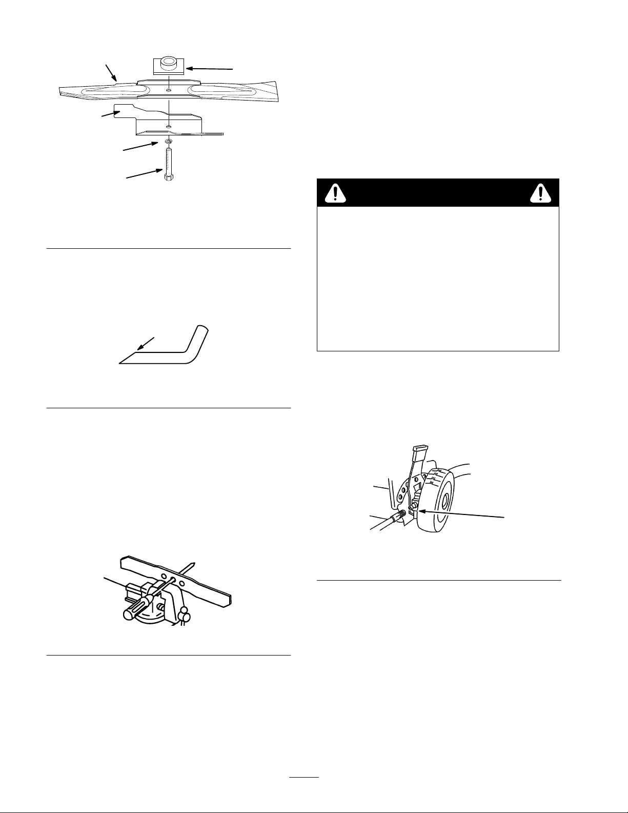
4
3
2
1
Figure
19
1. Blade
2.
3. Accelerator
bolt
Lock washer
4. Blade
5.
Blade driver
Sharpening the Blade
Using
a file, sharpen top side of the blade and maintain
the original cutting angle (Fig. 20).
1
5
Installing the Blade
1. Position
the blade onto the spindle and blade driver
,
with the curved blade tips pointing toward the mower
and the blade driver nesting in the recess of the blade
(Fig. 19).
2.
Install the accelerator
, lock washer
, and blade bolt
(Fig. 19).
3. T
ighten the blade bolt to 50 ft-lb (68 N
1627
m).
WARNING
POTENTIAL HAZARD
•
Operating the mower without the accelerator in
place could cause the blade to flex, bend, or
break.
WHA
T CAN HAPPEN
•
A broken blade could cause serious injury or
death to the operator or bystanders.
HOW T
•
O AVOID THE HAZARD
Do not operate the mower without the
accelerator.
Figure
20
1. Sharpen
Note:
at this angle only
The blade will remain balanced if same amount of
material is removed from both cutting edges.
Balancing the Blade
1. Check
Note: You can also check the balance using a
commercially manufactured, blade balancer
the balance of the blade by placing the center
hole of the blade over a nail or screwdriver shank
clamped horizontally in a vise (Fig. 21).
.
Figure
21
153
1007
Lubricating
the Self–propel
Drive
1. Wipe
1. Grease
2. Install
IMPORTANT
pr
the grease fittings on the rear height-of-cut
adjustors (Fig. 22) with a clean rag.
Figure
22
fitting
a grease gun onto each fitting in turn and gently
apply one or two pumps of #2 multi-purpose lithium
grease to each.
event pr
: Excess gr
oper wheel clutch operation.
ease may damage seals and
1
1018
2. If
either end of the blade rotates downward, file that
end (not the cutting edge or the end near the cutting
edge). The blade is properly balanced when neither
end drops.
16
Page 17
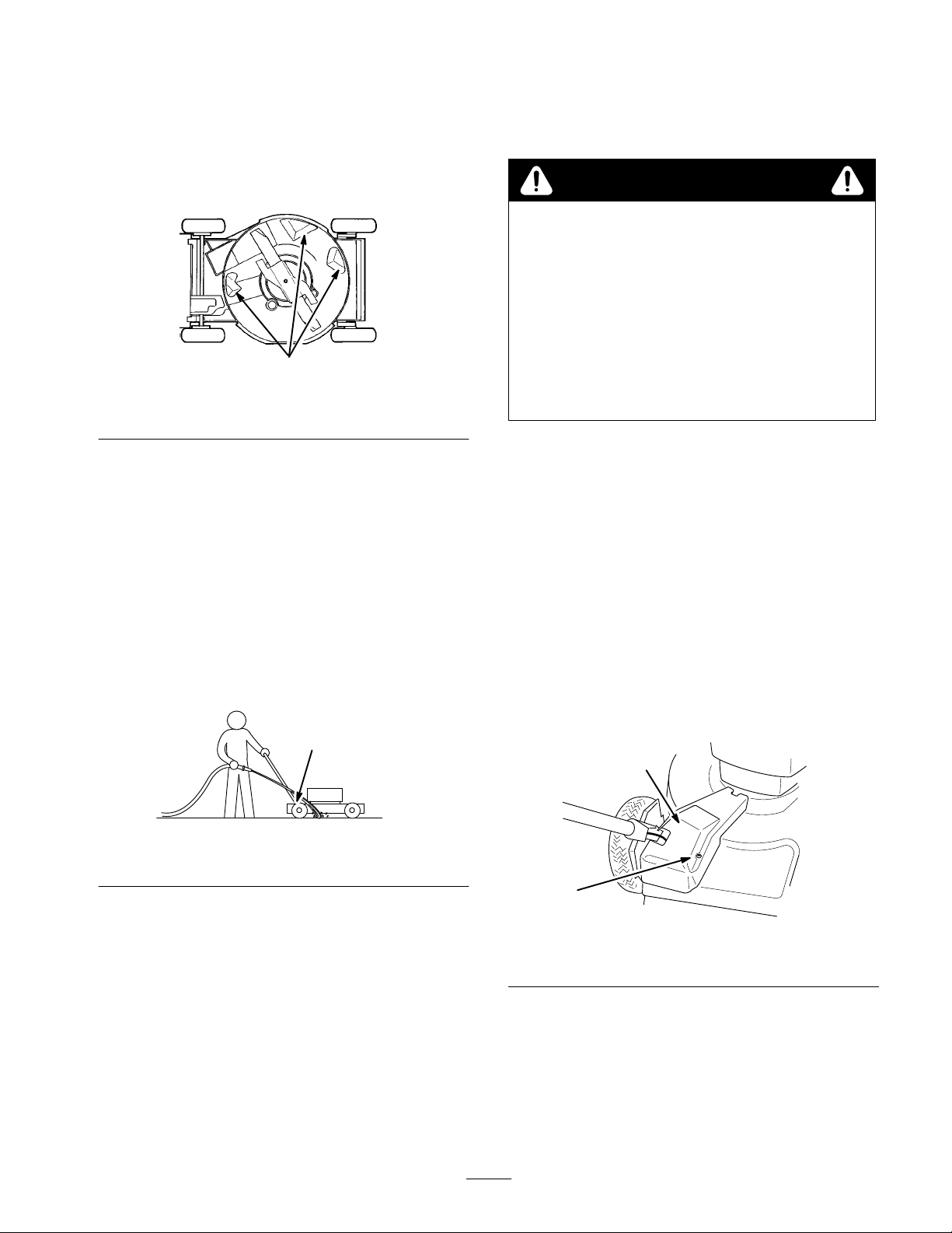
Cleaning
the Underside of the
Mower Housing
To
ensure best performance, keep the underside of the
mower housing clean. Be especially careful to keep the
kickers free of debris (Fig. 23).
1
1. Kickers
Washing Method
1. Position
surface near a garden hose.
the mower on a flat, concrete or asphalt
Figure
23
757
1.
Pull the wire off of the spark plug (Fig. 14).
2.
Drain the gasoline from the fuel tank. Refer to the
Draining Gasoline section, page 13.
WARNING
POTENTIAL HAZARD
•
Gasoline is extr
explosive and under certain conditions can
cause personal injury or pr
WHA
T CAN HAPPEN
• T
ipping the mower may cause fuel leakage
fr
om the carbur
HOW T
• A
3. T
4.
5. T
O AVOID THE HAZARD
void fuel spills by running the engine dry or
r
emoving gas with a hand pump; never siphon.
ip the mower on its left side with the air filter up
(Fig. 23).
Remove dirt and grass clippings with a hardwood
scraper
. A
void burrs and sharp edges.
urn the mower upright.
emely flammable, highly
operty damage.
etor or fuel tank.
2.
Start the engine.
3.
Hold the running garden hose at handle level and
direct the water to flow on the ground just in front of
the right rear tire (Fig. 24).
The blade will draw in water and wash out clippings.
Let the water run until you no longer see clippings
being washed out from under housing.
1
Figure
1. Rear
4. Stop
5. T
6.
7.
right wheel
the engine.
urn of
f the garden hose.
Start the mower and let it run for a few minutes to dry
out the moisture on the mower and its components.
While the engine is running, engage and disengage the
traction drive several times to dry it out.
24
Scraping Method
1093
6.
Refill the gas tank.
7.
Connect the spark plug wire (Fig. 14).
Cleaning
Keep
area under belt cover free of debris.
1. W
ith the engine turned of
the belt cover (Fig. 25) to the mower housing.
2
1. Belt
cover
2. Lift
of
area.
Install the belt cover
3.
Under the Belt Cover
f, remove the bolt securing
1
Figure
f the cover and brush out all debris from the belt
.
25
2. Bolt
1666
If
washing does not remove all debris from under the
mower
, tip it and scrape it clean.
17
Page 18

Troubleshooting
g
gp
gg
g
Y
our mower was designed and built for trouble-free operation. Check the following components and items carefully
problem continues, see your Authorized T
oro Service Dealer
.
. If a
PROBLEM
Engine will not start
Engine starts hard or loses power
Engine runs rough
Mower or engine vibrates
excessively
CORRECTIVE
1.
Fill fuel tank with fresh gasoline
2.
Move throttle lever to the F
3.
Press primer three (3) times
4.
Spark plug
•
Connect spark plug wire
•
Clean spark plug, check spark plug gap, replace if damaged
1.
Drain and refill fuel tank with fresh gasoline
2.
Replace air filter element
3.
Clean underside of mower deck
4.
Clean spark plug, check spark plug gap, replace if damaged
5.
Check engine oil
1.
Connect spark plug wire
2.
Clean spark plug, check spark plug gap, replace if damaged
3.
Move throttle lever from SLOW to F
4.
Replace air filter element
1.
Balance blade. Or if blade is bent, replace it.
2. T
ighten blade mounting bolt
AST position
ACTION
AST position
3.
Clean underside of mower deck
4. T
ighten engine mounting bolts
Uneven cutting pattern
Discharge chute plugs
Will not self-propel
1.
Place all four (4) wheels at same height
2.
Sharpen and balance blade
3.
Change mowing pattern
4.
Clean underside of mower deck
1.
Move throttle lever from SLOW to F
2.
Raise cutting height
3.
Slow down
4.
Allow grass to dry before mowing
5.
Clean underside of mower deck
1.
Adjust self-propelled cable
2.
Clean debris from under belt cover
AST position
.
18
Page 19
Storage
To
prepare the lawn mower for of
perform the recommended maintenance procedures. Refer
to the Maintenance section, page 12.
Store the mower in a cool, clean, dry place. Cover the
mower to keep it clean and protected.
f-season storage,
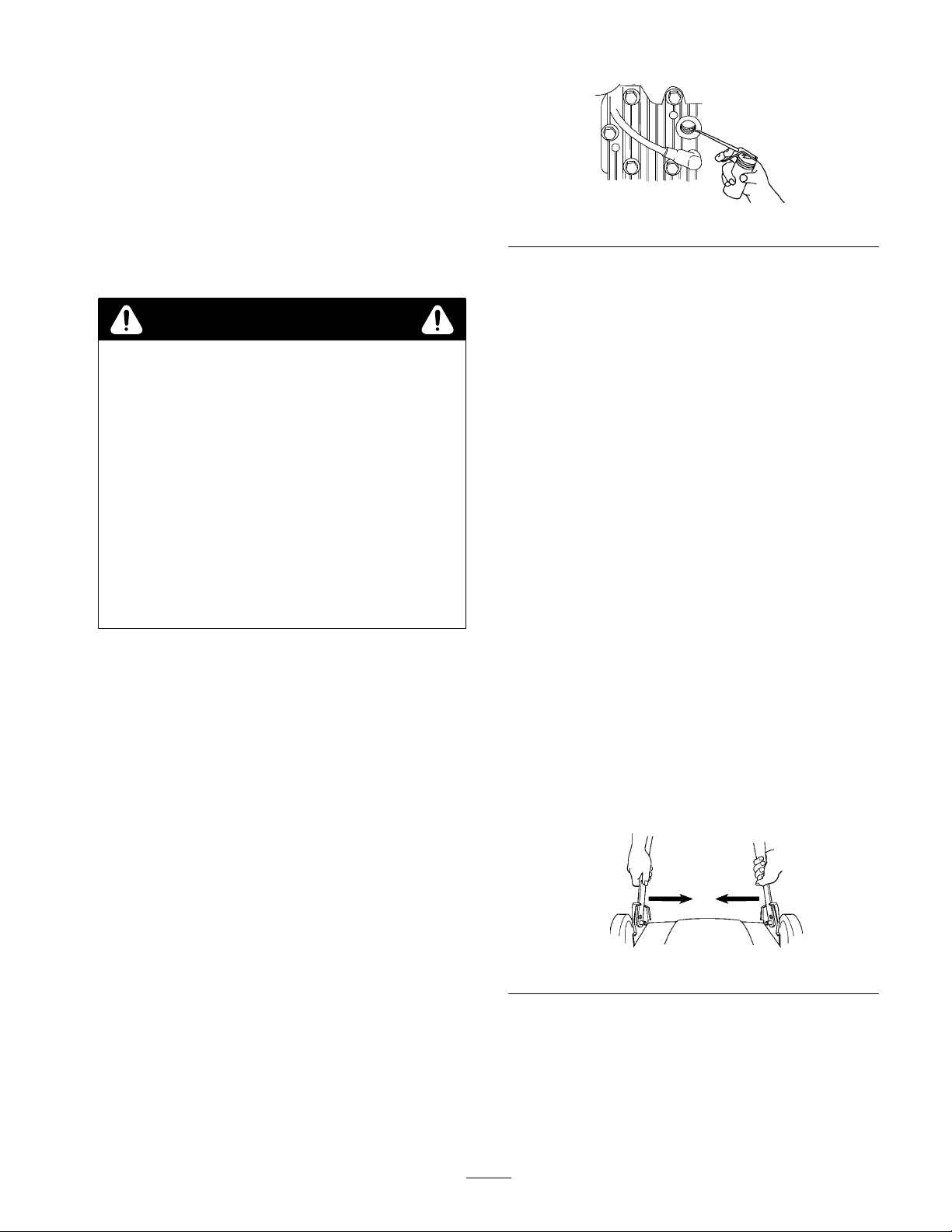
Figure
1009
26
Fuel
WARNING
POTENTIAL HAZARD
•
Gasoline can vaporize if stored over long
periods of time.
WHA
T CAN HAPPEN
• V
aporized fuel can explode if it comes into
contact with open flame.
HOW T
•
•
•
W
e recommend Toro Fuel Conditioner to stabilize fuel for
storage. If possible, the last fuel fill of the year should be
treated with T
Run the fuel tank empty when mowing the last time prior
to storage. The smaller the amount of fuel in the tank, the
shorter the time required to run the fuel system dry
the mower until engine stops from lack of fuel.
Preparing
O AVOID THE HAZARD
Do not store gasoline (fuel) over long periods of
time.
Do not stor
enclosur
furnace or water heater pilot light.)
Allow the engine to cool befor
enclosure.
e mower with fuel in the tank in an
e with an open flame. (Example: a
e storing in any
oro Fuel Conditioner
.
. Run
the Engine
5. Install
Cleaning
1. Clean
2.
spark plug but
wire.
do not
connect the spark plug
the Mower
the mower housing. Refer to the Cleaning the
Underside of the Mower Housing section, page 17.
Clean any dirt and chaf
head fins, and blower housing. Also remove grass
clippings, dirt, and grime from external parts of the
engine, shrouding, and top of the mower housing.
f from the cylinder
, cylinder
General
1.
Check the condition of the blade. Refer to the
Maintaining the Blade section, page 15.
2. T
ighten all nuts, bolts, and screws.
3.
Lubricate the wheels. Refer to the Lubricating the
Self–Propel Drive section, page 16.
4. T
ouch up all rusted or chipped paint surfaces. Paint is
available from an Authorized Toro Service Dealer
Folding
1. Push
handle slides past the stops on the handle brackets
(Fig. 27).
the Handle
in the right bottom handle section until the
.
1. While
2.
3.
4.
the engine is still warm, drain oil from
crankcase. Refer to the Changing Engine Oil section,
page 13.
Remove the spark plug (Fig. 14).
Using an oil can, squirt about one tablespoon of oil
through spark plug hole (Fig. 26).
Slowly rotate the engine several times, using the
starter rope, to distribute the oil.
19
2. Rotate
Figure
the handle toward the front of mower (Fig. 28).
27
1039
Page 20
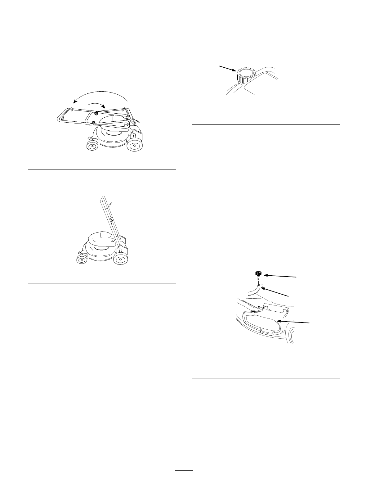
3.
Loosen the knobs securing the top handle section to
bottom section and fold the top handle section back
toward the rear of the mower into the storage position
(Fig 28).
Note:
When folding the handle, do not allow the cables to
get pinched, crimped, or caught on the handle knobs.
Fold the handle only in the direction illustrated (Fig. 28).
6.
Perform the recommended maintenance procedures.
Refer to the Maintenance section, page 12.
7.
Fill the fuel tank (Fig. 30) with fresh, clean gasoline.
1
Figure
30
1. Fuel
tank cap
1626
Figure
28
Note:
For short term storage, place the handle in the
position shown in Figure 29.
Figure
29
Removing
From Storage
1679
1684
8. Check
9.
the engine oil level.
Connect the spark plug wire (Fig. 14).
Accessories
Accessories may have been shipped with your mower or
are available from your Authorized T
proper installation, follow these instructions.
Rear
Grass Catcher
Installing the Discharge Tunnel
1. Stop
2.
the engine and disconnect the spark plug wire.
Remove the knob and side cover clamp (Fig. 31).
oro Dealer
1
2
. For
1. Unfold
2.
3.
4.
5.
the handle. Refer to the Assembly section,
page 7.
Check and tighten all fasteners.
Remove the spark plug (Fig. 14) and spin the engine
rapidly using the starter to blow excess oil from the
cylinder.
Clean the spark plug or replace it if it is cracked,
broken, or the electrodes are worn.
Install the spark plug and torque it to 15 ft.-lbs.
(20 N
m).
1. Knob
2. Side
3. Remove
20
Figure
31
3.
Side opening cover
cover clamp
and save the three bolts securing the
dischar
ge cover to the mower (Fig. 32). Save the cover
and bolts for future use.
3
m–4275
Page 21
5
4
2
4
3
1
32
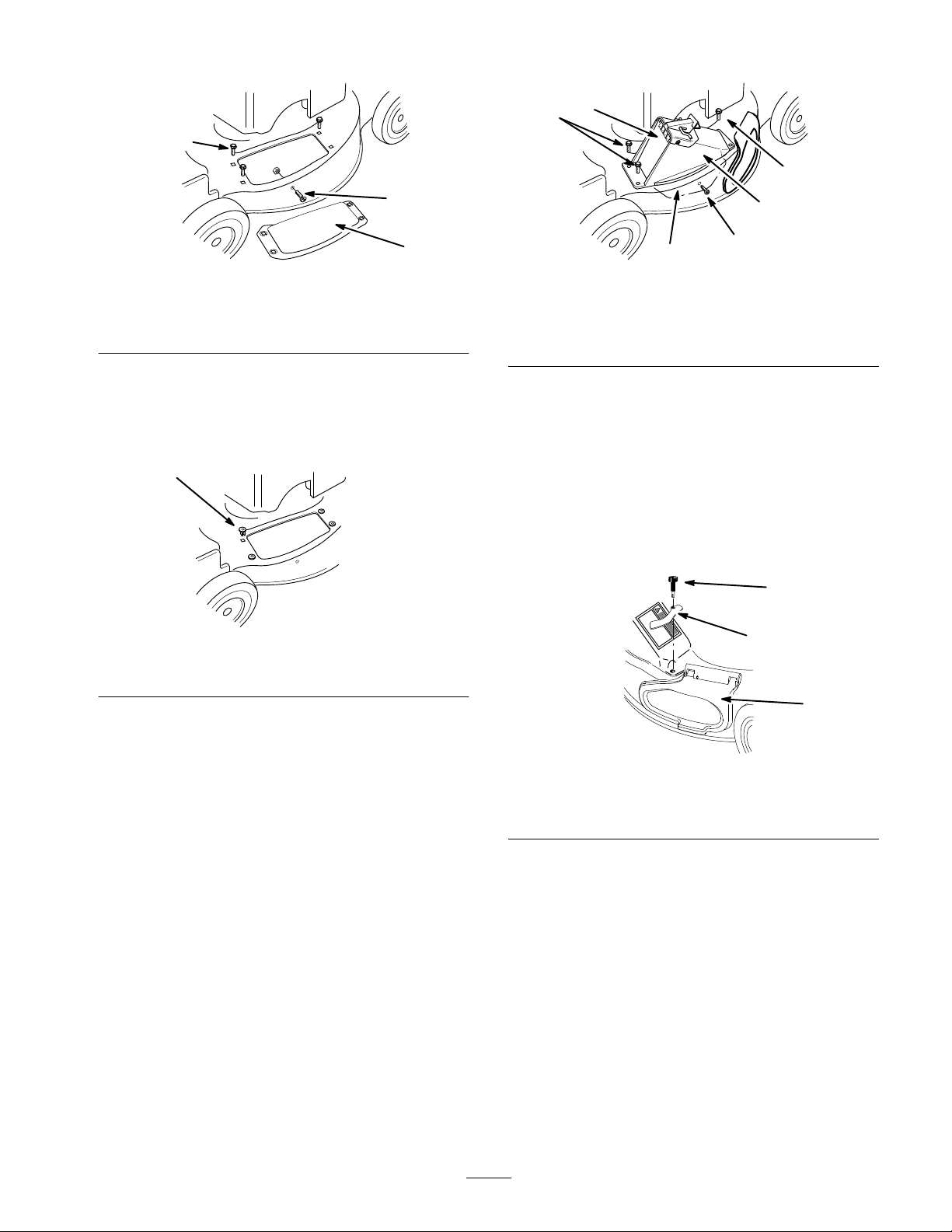
3.
Screw and nut
1. Discharge
2.
Bolt (3)
4. Remove
Figure
cover
the screw and nut from side of the mower
(Fig. 32). Save them for future use.
5.
Install four grommets supplied with the grass catcher
into the four square holes in the mower (Fig. 33).
1
1. Grommet
Figure
(4)
33
1
m–4275
2009
2
3
1. Discharge
2. Tongue
3.
Self-tapping screw
9. Install
the self-tapping plastite screw supplied with the
Figure
tunnel
34
4.
Bolt (3)
5.
Discharge tunnel door
grass catcher into the side hole and tongue, and
partially tighten the screw (Fig. 34).
10.
Using three screws supplied with the grass catcher
fasten the dischar
11.
Secure the front, right corner of the dischar
ge tunnel to the mower (Fig. 34).
ge tunnel
and the side opening cover with the side cover clamp
removed previously and the long knob supplied with
the grass catcher (Fig. 35)
1
2
2010
,
6. Insert
the tongue of the discharge tunnel into the
mower (Fig. 34).
7.
Align the holes in the tunnel with the grommets in the
mower (Fig. 34).
8.
Ensure that the hole in the tongue aligns with the hole
in the side of the mower (Fig. 34).
1. Long
2.
knob
Side cover clamp
Figure
35
3.
Side opening cover
3
m–4274
21
Page 22
DANGER
POTENTIAL
•
If the side opening cover is not secur
clamped in place, debris could be thr
the side opening.
WHA
T CAN HAPPEN
• Thr
own debris can cause serious personal
injury or death to the operator or bystanders.
HOW T
•
Always ensur
cover is closed and locked in place by the side
cover clamp or that the side discharge chute is
secur
mower.
12.T
ighten all four screws and the long knob.
13.
Open and close the tunnel door to ensure that it moves
freely (Fig. 34).
HAZARD
O AVOID THE HAZARD
e that either the side opening
ely seated in place befor
ely
own out of
e starting the lawn
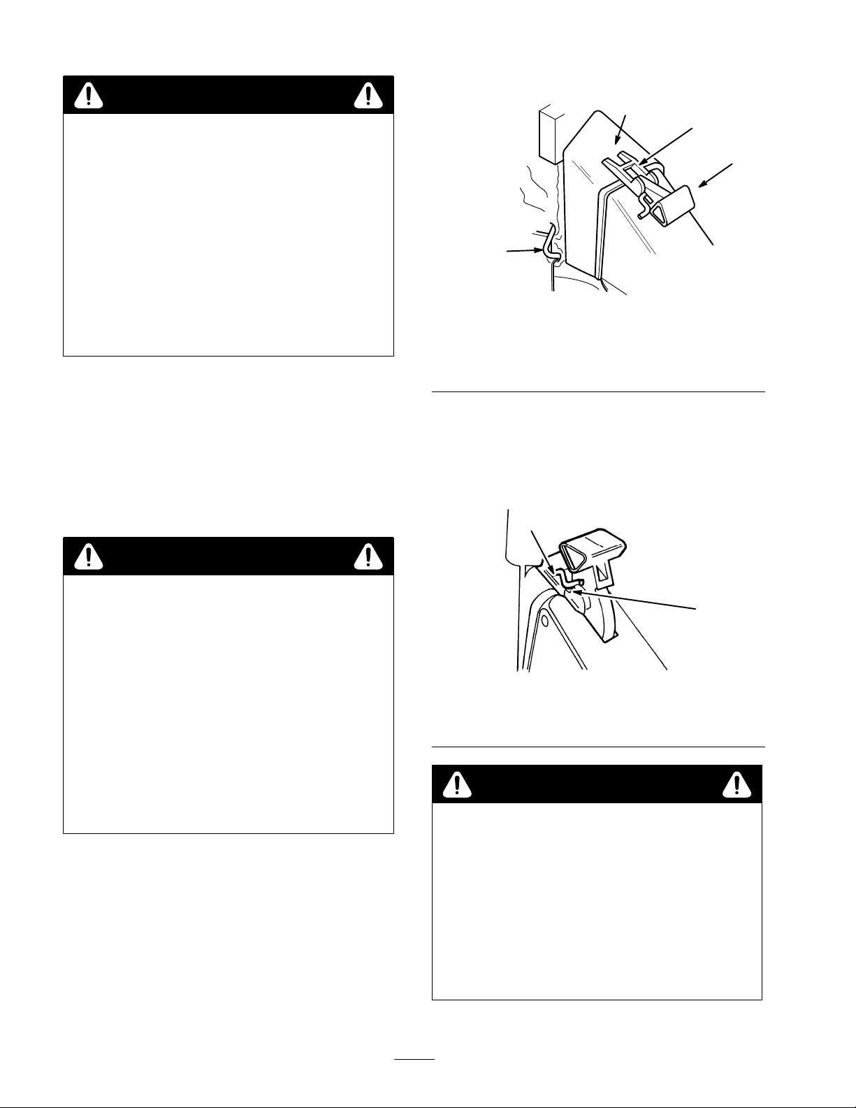
Set the rear of the bag frame onto the lower handle.
4.
2
4
36
Figure
1. Handle
2.
3.
5. Pull
fully forward
Bag door
Bag door latch
4.
Bag rod hook in front of
handle bracket
the handle rearward until the handle latch locks in
the notch in the bag door latch (Fig. 37).
3
1
2022
Installing the Grass Bag
Note: T
the grass bag and ensure that the dischar
closed and secured.
o recycle grass instead of catch it, do not install
ge tunnel door is
DANGER
POTENTIAL HAZARD
• Thr
own objects may r
door does not close completely
WHA
T CAN HAPPEN
• Thr
own objects can cause serious personal
injury or death.
HOW T
•
O AVOID THE HAZARD
If the discharge door cannot be closed because
grass clippings clog the discharge ar
engine and gently move the discharge door
handle back and forth until the door can be
closed completely
r
emove the obstruction with a stick; not your
hand.
1.
Stop the engine and wait for all moving parts to stop.
2.
Ensure that the dischar
(door closed) (Fig. 36).
3.
Fit the bag door opening over the dischar
opening as shown in Figure 36.
The bag door latches should straddle the door handle,
and the bag rod hook should be in front of the handle
bracket.
esult if the discharge
.
ea, stop the
. If door still cannot be closed,
ge door handle is fully forward
ge tunnel
The dischar
ge door in the mower housing is now open
and the bag is locked into position. The latch should
seat in bottom of the notch.
1
Figure
37
1. Handle
notch
latch locked in bag
2. Notch
in bag door latch
DANGER
POTENTIAL
•
Grass clippings and other objects can be
thr
own fr
WHA
T CAN HAPPEN
•
Objects thrown with enough for
serious personal injury or death to the operator
or bystander
HOW T
•
Never open the door on the discharge tunnel
when the engine is running.
HAZARD
om an open discharge tunnel.
ce could cause
.
O AVOID THE HAZARD
2
548
22
Page 23
DANGER
5. Close
the cover
.
Removing the Side Discharge Chute
POTENTIAL HAZARD
•
A worn grass bag could allow small stones and
other similar debris to be thrown in operator
or bystander’s dir
WHA
T CAN HAPPEN
• Thr
own objects can cause serious personal
injury or death to the operator or bystanders.
HOW T
•
O AVOID THE HAZARD
Check the grass bag fr
damaged, install a new genuine T
eplacement bag that has this or a similar
r
warning.
ection.
equently
. If it is
oro
Emptying the Grass Bag
1. Stop
2.
3.
4.
Side
the engine and wait for all moving parts to stop.
Lift the door latch until it clears the bag notch and
move the dischar
Grasp the bag frame handle and the rear of the grass
bag and lift the bag of
Gradually tip bag forward to empty clippings.
ge door handle forward (Fig. 36).
f of the mower
.
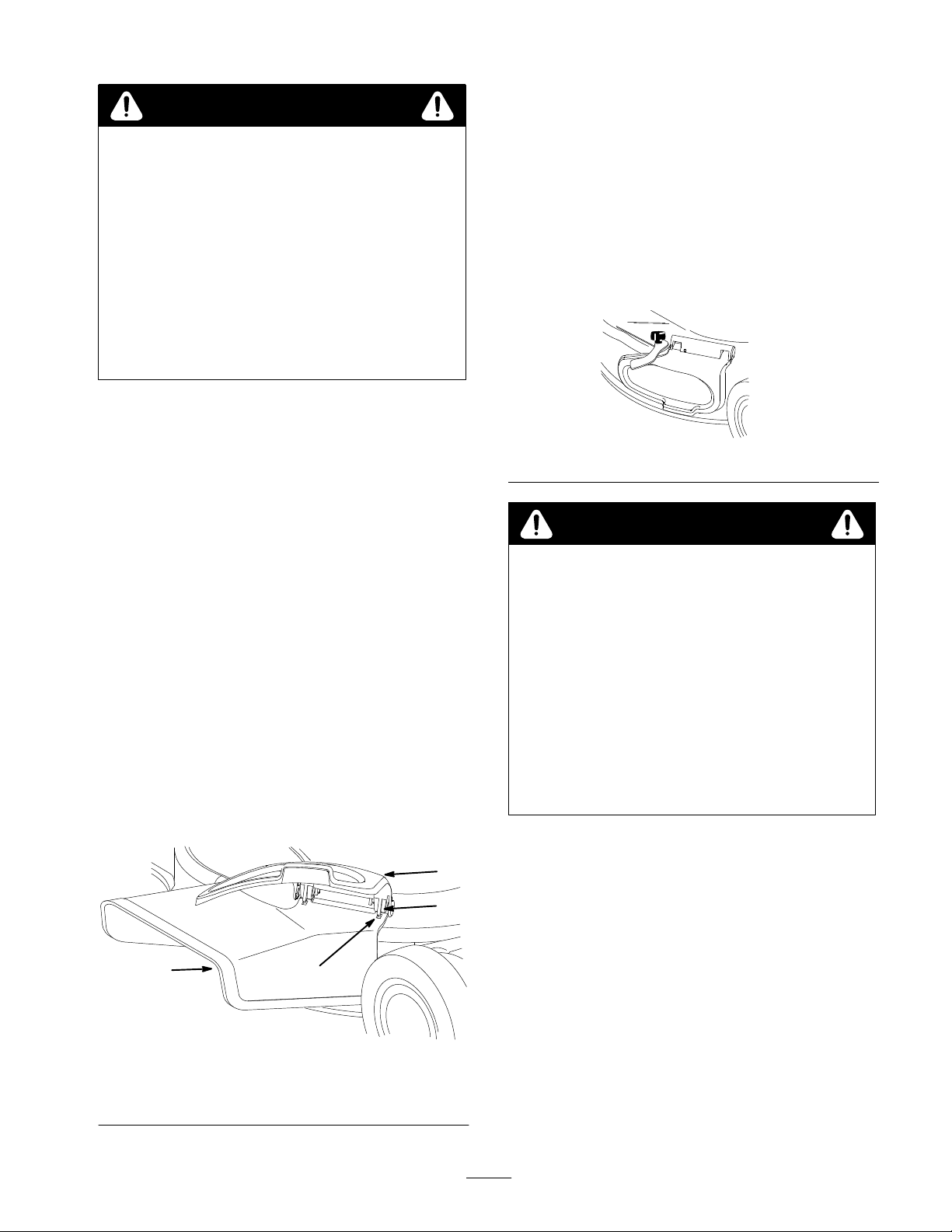
Discharge Chute
Installing the Side Discharge Chute
1. Stop
2.
3.
4.
the engine and disconnect the spark plug wire.
Remove the knob and side cover clamp, then replace
the knob in the hole and save the clamp for future use
(Fig. 31).
Lift up on the side opening cover (Fig. 31).
Slide the chute over the opening with the slots in the
chute lined up with the tabs under the cover (Fig. 38).
1. Stop
’s
2.
3.
4.
the engine and disconnect the spark plug wire.
Open the side opening cover and remove the side
dischar
ge chute (Fig. 38).
Close the cover
Remove the knob, then install the side cover clamp
and the knob, securing the side opening cover
(Fig. 31 and 39).
.
Figure
m–4279
39
DANGER
POTENTIAL
•
If the side opening cover is not secur
clamped in place, debris could be thr
the side opening.
WHA
T CAN HAPPEN
• Thr
own debris can cause serious personal
injury or death to the operator or bystanders.
HOW T
•
Always ensur
cover is closed and locked in place by the side
cover clamp or that the side discharge chute is
secur
mower.
HAZARD
O AVOID THE HAZARD
e that either the side opening
ely seated in place befor
e starting the lawn
ely
own out of
2
m–4196
1. Side
opening cover
2.
Side discharge chute
Figure
1
3
4
38
3. Tab
4. Slot
23
Page 24

 Loading...