

Page 1
Electric Winch Kit
Twister Utility Vehicle
Model No. 19053
Form No. 3326-468 Rev A
Installation Instructions
Installation
Preparing the Vehicle
1. Position the machine on a level surface. Set the parking
brake, stop the engine, and remove the key.
Caution
If you leave the key in the ignition switch, someone
could accidently start the engine and seriously
injure you or other bystanders.
Remove the key from the ignition switch before
you do any maintenance.
2. Remove the hood from the vehicle by removing the 2
screws in the top of the hood, the 2 bolts on each fender,
and the 4 bolts from the bottom of the hood.
3. Remove the cargo box by removing the prop rod and
one of the brackets on the back of the frame. Lift up on
the box and slide it off of the frame.
4. Remove the fuse box cover.
5. Remove the rubber boot from the positive (+) battery
cable and disconnect the battery cable from the battery.
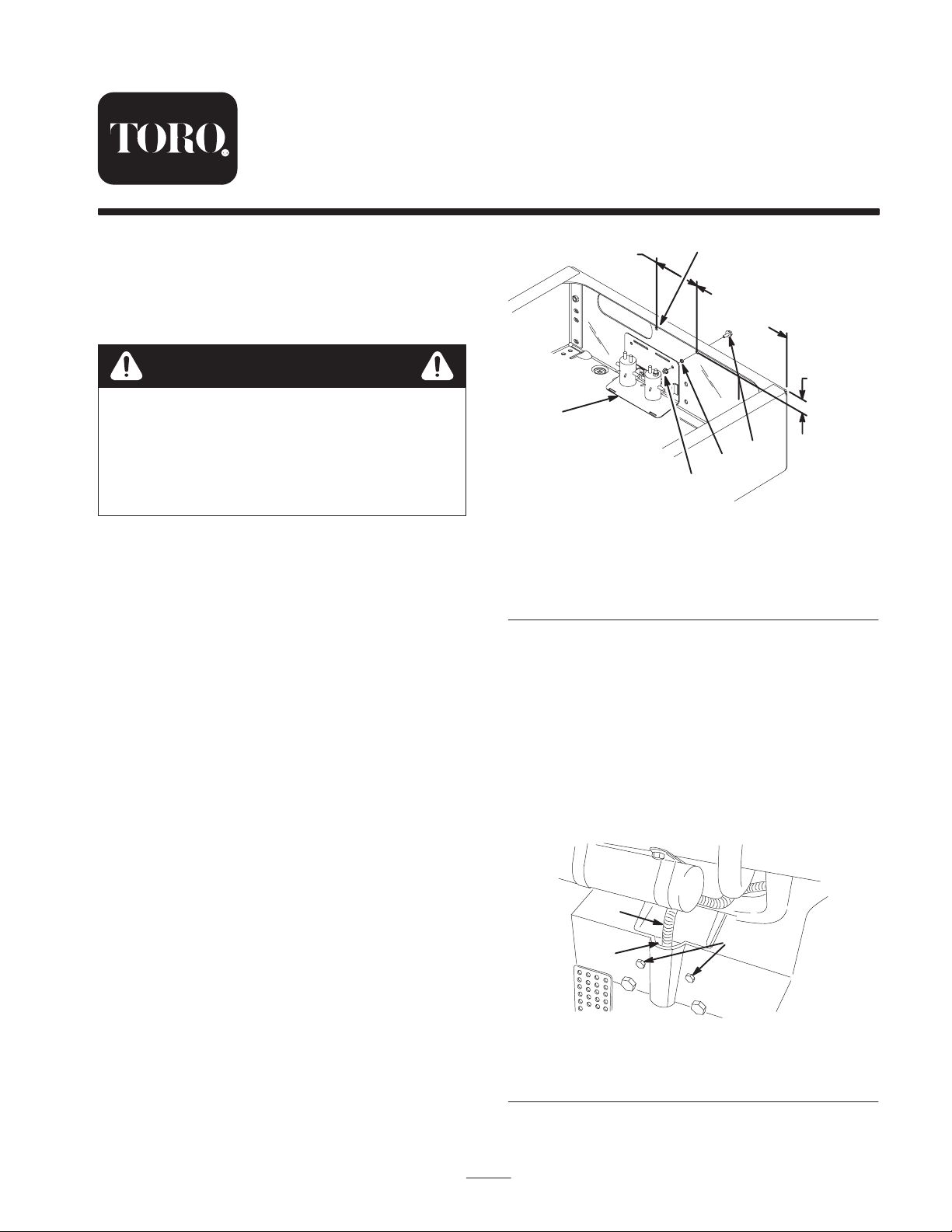
6 in.
(15.24 cm)
1
13 in.
(33 cm)
1-3/8 in.
(3.5 cm)
2
3
4
5
Figure 1
1. 0.30 in. (7.6 mm)
diameter hole
2. Solenoid assembly
3. Bolt, 1/4 x 3/4 in.
4. Spacer
5. Flange nut, 1/4 in.
Routing the Wire Harness
1. Remove the 2 small bolts securing the panels to the
front of the operator’s compartment (Fig. 2).
m–5666
Attaching the Solenoid Assembly
1. Locate, mark, and drill 2 holes (0.30 in. [7.6 mm]
diameter) in the rear frame as shown in Figure 1.
2. Attach the solenoid assembly to the inside of the rear
frame with 2 bolts (1/4 x 3/4 in.), spacers, and flange
nuts (1/4 in.) (Fig. 1).
2001 by The Toro Company
8111 Lyndale Avenue South
Bloomington, MN 55420-1196
2. Using a screw driver or similar tool, pry apart the
overlap in the harness opening in the vehicle
compartment to allow greater access.
Note: Make sure that the vehicle is in a temperature above
68 degrees so that the opening in not stiff when prying.
3
1
2
Figure 2
1. Mounting bolts
2. Harness opening
3. Existing harness
All Rights Reserved
Printed in the USA
1
Page 2
3. Carefully tape the 3 loose control plug terminals and
wire to the harness to ease harness routing. Tape the
terminals to the end of the harness, away from the
solemoid assembly.
4. Route the harness through the hole in the front of the
rear frame.
5. Using a wire, hook the front plug of the harness and
carefully pull it through the tube to the front of the
vehicle (above the tow bar).
Note: To ease in routing the harness, have one person
feeding the harness into the tube while another person is
pulling. Use caution not to damage the harness end when
pulling.
Installing the Control Plug
1. Remove the tape from the terminals and wire. Loop the
control plug back into the tube at the front of the
vehicle and feed it up through the harness opening
below the dash (Fig. 2).
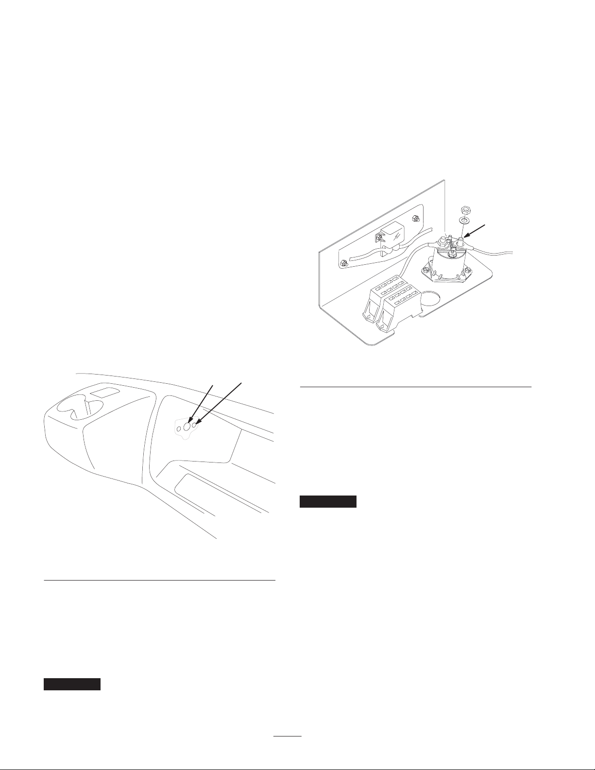
2. Using the control plug as a template, locate and mark
the holes in the glove box in the approximate location
shown in Figure 3. Remove the control plug and drill a
0.95 diameter hole using a 61/64 in. drill bit and (2)
0.201 diameter holes using a #7 drill bit in the side of
the glove box as shown in Figure 3.
2
1
6. Connect the remote control to the control plug.
Connecting the Wire Harness
1. Remove the nut securing the positive battery cable to
the starter solenoid (Fig. 4).
2. Route the other end of the harness toward the fuse
panel. Insert the ring end of the terminal of the harness
onto the solenoid post and secure it with the nut
removed in step 1.
1
m–5623
Figure 4
1. Positive post—solenoid
m–5677
Figure 3
1. 0.95 diameter hole 2. 0.201 diameter hole
3. Attach the control plug to the glove box with the 2
screws.
4. Route the 3 control plug terminals below the dash and
plug them into the control plug in the glove box.
5. Secure the wire harness to the frame and the existing
wire harness with 4 wire ties.
Important Keep the harness and plugs away from hot
or moving parts.
3. Locate and remove the screw securing the engine
ground wire to the front right corner of the engine skid
plate.
4. Secure the engine ground wire and other harness ring
end terminal to the engine.
5. Secure the wire harness to the rear frame member with
a wire tie and the right frame member with 2 wire ties.
Important Keep the harness away from hot or moving
parts.
6. Insert the upper tabs on the solenoid cover into the top
slots of the solenoid assembly; then snap the lower tabs
into the slots on the bottom of the assembly.
Attaching the Winch to the Front of the
Vehicle
1. Attach the roller fairlead to the winch and winch mount
with 2 bolts (5/16 x 3 in.), 4 flat washers (5/16 in.), and
2 locknuts (5/16 in.) (Fig. 5).
Note: The rear bolt must be inserted through the bottom of
the winch mount and the front bolt must be inserted
through the top of the roller fairlead plate (Fig. 5).
2
Page 3

4
3
7
12
1
7. Connect the front plug on the wire harness to the winch
plug.
8. Install the cargo box, prop rod, and hood.
11
8
Connecting the Winch to the Rear of the
Vehicle
If you already have a rear receiver hitch, the winch can be
5
2
attached to the rear of the vehicle.
1. Loop the front end of the wire harness back into the
frame tube.
6
11
10
9
m–5668
Figure 5
1. Receiver assembly
2. Bolt, 3/8 x 1-1/4 in.
3. Locknut, 3/8 in.
4. Clevis pin, 1/2 x 3 in.
5. Hairpin cotter
6. Clevis pin, 5/8 x 3-1/2 in.
7. Roller fairlead
8. Winch
9. Winch mount
10. Bolt, 5/16 x 3 in.
11. Flat washer, 5/16 in.
12. Locknut, 5/16 in.
2. Remove the pin in the roller fairlead and slide the top
roller out (Fig. 6).
3. Lay the cable and hook on the lower roller, install the
top roller, and secure it with the pin (Fig. 6).
1
2
2. Follow steps 5–6 in Attaching the Winch to the Front of
the Vehicle, page 2.
3. Connect the rear plug on the wire harness to the winch
plug.
Operation
Important Refer to the winch owner’s manual included
in this kit for operating instructions.
Note: Unplug the remote control from the control plug
when not in use.
3
m–5678
Figure 6
1. Roller fairlead
2. Pin
3. Top roller
4. Slide the receiver assembly into the front channel and
attach it to the front of the frame with 2 bolts (3/8 x
1-1/4 in.) and 2 locknuts (3/8 in.) (Fig. 5).
5. Secure the receiver to the frame channel with the clevis
pin (1/2 x 3 in.) and hairpin cotter (Fig. 5).
6. Slide the winch mount into the receiver and secure it
with the clevis pin (5/8 x 3-1/2 in.) and hairpin cotter
(Fig. 5).
3
Page 4

 Loading...