

Page 1

2-CYCLE GTS 120 ENGINE SERVICE MANUAL
Table of Contents – Page 1 of 1
PREFACE
I. GENERAL INFORMATION
SAFETY INSTRUCTIONS
MAINTENANCE
MODEL AND SERIAL NUMBERS
TWO-CYCLE ENGINE THEORY AND OPERATION
CARBURETOR THEORY AND OPERATION
SPECIAL TOOLS LIST
II. MAINTENANCE
AIR CLEANER
SPARK PLUG
EXHAUST SYSTEM
DECARBONING CYLINDER HEAD
IGNITION TIMING (MODEL 47PZ2 ONLY)
IGNITION TIMING (DIAL INDICATOR)
CONTACT POINTS AND CONDENSER MODEL47PZ2 ONLY
IGNITION COIL
GOVERNOR
GOVERNOR OPERATION
FUEL TANK
CARBURETOR
STORAGE
III. TROUBLESHOOTING AND TEST PROCEDURES
PRELIMINARY TROUBLESHOOTING
ENGINE BRAKE AND IGNITION SWITCH
BBC APPLICATIONS
FUEL TANK
TESTING COMPRESSION
CRANKCASE
ENGINE TROUBLESHOOTING CHART
IV. ENGINE REMOVAL, DISASSEMBLY, ASSEMBLY AND REPAIR INSTRUCTIONS
ENGINE REMOVAL
ENGINE DISASSEMBLY AND REPAIR
RECOIL STARTER REPAIR
CARBURETOR REPAIR
ENGINE ASSEMBLY AND REPAIR
SERVICE DATA SPECIFICATIONS
Page 2
Page 3
PREFACE
This service manual was written expressly for TORO Two-Cycle Rotary Mowers.
All
units with the model number
have been taken into consideration.
The Toro Company has made every
tool for the service and maintenance of your
assure proper and effective performance, you are urged to read this manual
carefully.
of
The purpose
this manual is to provide the Service Dealer with working
guidelines of maintenance, troubleshooting, test, and overhaul procedures.
The Toro Company reserves the right to change product specifications or this
manual without notice.
47P22,47PD3,47PE4,
effort
to make this service manual a useful
TORO
Rotary Mower Engine. To
and
47PF5
engines
The Toro Company
Service
Department
COPYRIGHT ALL RIGHTS RESERVED
The
Toro
MINNEAPOLIS,
Company
MN
55420
1986
U.S.A.
i
Page 4
TABLE
TOPIC PAGE E
1
.
GENERAL INFORMATION
Safety Instructions
Maintenance
Model and Serial Numbers
Two-cycle Engine Theory and Operation
Carburetor Theory and Operation
Engine Specifications
Fastener Torque Specifications
Special Tools
II.>
MAINTENANCE
Air Cleaner
Spark Plug
Exhaust System
Decarboning Cylinder Head
Ignition Timing (Model 47PZ2 Only)
Ignition Timing (Dial Indicator)
Contact Points and Condenser (Model 47PZ2 Only)
Ignition Coil (Model 47P22 Only)
Ignition Coil (Models 47PD3.47PE4. 47PF5)
Governor
Governor Operation
Fuel Tank
Carburetor
Storage
111
.
TROUBLESHOOTING AND TEST PROCEDURES
Preliminary Troubleshooting
Spark Intensity
Engine Brake and Ignition Switch
BBC Applications
Fuel Tank
Testing Compression
Crankcase
Engine Troubleshooting Chart
IV
.
ENGINE REMOVAL, DISASSEMBLY, ASSEMBLY AND REPAIR INSTRUCTIONS
Engine Removal
Engine Disassembly and Repair
Recoil Starter Repair
Carburetor Repair
Service Data Specifications
Maintenance Record
Maintenance Record
.......................................................................................
.......................................................................................
..................................................................
........................................................................................
.......................................................................................
...........................................................................................
.....................................................
.......................................................................................
................................................................................
.......................................................................................
.............................................................................
......................................................................................
..............................................................................
..................................................................................
..............................................................................
..................................................................................
................................................................................
............................................................................
.................................................................................
............................................................................
...............................................................................
............................................................................
............................................................................
....................................................................
...................................
.................................................................
...................................................................
......................................................................
..............................................................
....................................................................
.................................................................
.....................................................................
................................................................
...................................................................
................................................................
......................................................................
OF
CONTENTS
.,.
...................................
..........................................................
..............................................
..................
..................................
......................
..........................................
..................................
........
1-1
1-1
1-2
1-2
1-2
1-4
1-5
1-5
1-6
11-1
11-1
11-1
11-1
11-2
11-2
11-3
11-3
11-3
11-4
11-4
11-5
11-5
11-6
11-6
111-1
111-1
111-1
111-1
111-2
111-2
111-2
111-3
111-4
1v-1
1v-1
1v-1
1v-1
1v-2
1v-4
1v-6
1v-7
Page 5
SAFETY INSTRUCTIONS
Your rotary mower at the time of its manufacture,
meets the blade safety requirements of the Consumer Product Safety Commissions Safety Standard for Walk Behind Power Lawn Mowers.
representative sample was tested and verified by
an independent laboratory for compliance with
the B71.1-1980 Specifications of the American
National Standards Institute. However, improper
use or maintenance by the operator or owner
can still result in injury. To reduce the potential
for injury follow these safety instructions.
This machine is equipped with a blade brake
which is designed to stop the blade within
seconds when the control lever is released.
Check to be sure the control and brake function
correctly before each use of the mower. Repair
any defective or damaged safety components
before operation is commenced. To further
reduce the possibility of injury, always stop the E. Wipe up any spilled gasoline.
engine before leaving the operator’s position.
This safety symbol means
WARNING
PERSONAL SAFETY INSTRUCTION
Read the instruction because
do
with safety. Failure to comply with
the instruction may result in personal
injury.
Before Operating
1.
Operate your mower only after reading the engine is running. Stay behind the handle
Operators Manual.
available by sending the complete model 12. During operation the grass defector
and serial number to: The Toro Company, plete bagging assembly must be installed on
81 11 Lyndale Avenue South, Minneapolis, the mower.
Minnesota
2.
Never allow children to operate the mower
or adults to operate mower without
proper instructions.
3. Become familiar with the controls and know
how to stop the engine quickly.
4.
Keep everyone, especially children and pets,
away from the area of operation. Remove
sticks, stones, wire and any other debris that
might be picked up and thrown by the blade.
5.
TAMPERING WITH
SAFETY DEVICE
RESULTS IN NONCONFORMANCE WITH
SAFETY STANDARD, MAY RESULT IN PER-
SONAL INJURY. Each time before operating
the mower, check for damage or abnormal
wear.
defective or damaged, repair or replace it
before operation is commenced.
55420.
If
a safety device, shield, or decal
Attn: Publications. 13. Stop the engine and wait for all moving parts
OR
or
CAUTION
it
has to
A
replacement manual is
OR
DEFEATING
COMPONENT WHICH
A
3
-
-
A
A
is
1-1
6. Wear long pants and substantial shoes.
not operate the mower while wearing
sandals, tennis shoes, sneakers or shorts.
Do not wear loose fitting clothing that could
get caught in moving parts.
If
long grass will be cut, set the height-of-cut
7.
in the highest position. After mowing, reinspect the area and remove all debris. Then
lower the height-of-cut and mow the grass
again.
8. Since gasoline is highly flammable, handle it
carefully
A. Use an approved gasoline container.
B.
Do not
hot or running.
C. Do not smoke while handling gasoline.
D.
Fill the fuel tank outdoors and up to about
one-half inch from the top of the tank, not
the filler neck.
While Operating
9. Cutting the grass with a rotary mower demands attention. Always maintain secure
footing, balance and control.
10. Cut the grass during the daytime or when
there
from side to side, but avoid slopes when the
grass is wet.
is dry for best results.
11. Keep face, hands and feet away from the
mower housing and cutter blade while the
until the engine and all moving parts stop.
to stop before removing the bag, bagging
assembly, or unclogging the discharge
chute.
the high tension wire from the spark plug to
prevent the possibility
Use a stick to remove the obstruction.
If
a solid object is hit by the blade or
14.
mower vibrates abnormally, stop the engine
immediately. Disconnect the high tension
wire from the spark plug to prevent the
possibility of accidental starting. Then check
the mower for possible damage, bent blade,
an obstruction or loose parts. Repair the
mower before using it again.
15. Stop the engine before adjusting the
height-of-cut.
If
16.
a gravel driveway, road or path must be
crossed, stop the engine
fill
the fuel tank when the engine is
is
adequate artificial light. Cut slopes
If
possible, mow when the grass
or
If
the chute must be unclogged, pull
of
accidental starting.
so
loose sand and
Do
com-
if
the
-
Page 6
rocks are not thrown.
17.
Before leaving the operator’s position behind
the handle, stop the engine and wait for all
moving parts to stop. Do not walk in front of
the mower while the engine is running. Disconnect the high tension wire from the spark
plug
if
the mower will be unattended.
18.
Do
not touch any part of the engine while it is
running or shortly after it is stopped because
the engine will be hot enough to cause a
burn.
Muffler
children and pets away.
MAINTENANCE
Before the mower is serviced or adjusted,
19.
stop the engine and remove the key from the
switch. Disconnect the high tension wire from
the spark plug to prevent the possibility of
accidental starting.
20.
To assure the mower is in safe operating
condition, keep all nuts, bolts and screws
tight. Assure the blade capscrew is tightened
to the proper torque.
21.
If
major repairs are ever needed or
tance is desired, contact an Authorized
TORO Service Dealer.
22.
If
the mower must be tipped when it is
serviced or adjusted, drain the gasoline from
the fuel tank.
23.
If
a guard, safety device or safety decal is
damaged, replace the defective part(s) be-
fore operating the mower.
24.
To reduce potential fire hazards, assure the
mower is free
leaves and accumulations of dirt.
25.
The grass bag must always be in good condition; therefore, check it before each use to
assure the bag is not torn
Always replace a defective grass bag.
26.
Allow the engine to cool before storing the
mower in any enclosure such as a garage or
storage shed.
any open flame or where gasoline fumes
may be ignited by a spark.
27.
Do not overspeed the engine by changing
the governor settings. Recommended speed
of the engine is
and accuracy, have an Authorized TORO
Service Dealer check the engine speed with
a tachometer.
28.
At the time of manufacture the mower conformed to the safety standards in effect for
is
extremely hot. Keep
of
excessive grease, grass,
or
deteriorated.
Do
not store the mower near
3000
rpm. To assure safety
if
assis-
rotary mowers. To assure optimum performance and continued safety certification of
the mower, use genuine TORO replacement
parts and accessories. Replacement parts
and accessories made by other manufacturers may result in nonconformance with
the safety standards.
MODEL AND SERIAL NUMBERS
The TORO Two-cycle Rotary Mower has two sets
of identification numbers. There is a model and
serial number to identify the engine and a model
and serial number to identify the chassis. The
engine identification numbers are stamped into
the blower housing behind the air cleaner. Model
I
47PF5 engines built for
identification numbers stamped in the blower
housing above the spark plug. Engine models
47PE4 and 47PF5 have serial numbers that start
with the number
zone start application. The number 2 indicates
BBC application and the number
commercial application.
The chassis identification numbers are located on
a decal on the back
the rear wheels.
In any correspondence concerning the mower,
supply the model and serial numbers to assure
that thecorrect information and replacement parts
are obtained. Genuine TORO replacement parts
may be ordered through your
rized Service Dealer.
TWO-CYCLE ENGINE THEORY AND
OPERATION
Theory
Two-cycle engines have special advantages
which make their use more practical in certain
applications. Two-cycle engines are lightweight
with an excellent power to weight ratio and can
be operated in any position. They are also
notably easy to maintain and service because of
their uncomplicated design.
The TORO Two-cycle Engine used on the TORO
Rotary Mowers is a third-port, loop scavenged
design. This design name describes the path of
/
the fuel
bustion chamber, and the exhausting of spent
gases.
In a loop-scavenge engine, a high pressure area
is created in the crankcase by the downward
movement of the piston. Pressurized fuel-air
mixture rushes into the combustion chamber
through the intake ports and is directed toward
the cylinder head. This fresh mixture then strikes
the cylinder head and loops down forcing burnt
gases in the combustion chamber out through
air mixture into the crankcase and com-
1, 2 or
of
1986
3. The
the mower housing, between
have the engine
number 1 indicates
local
3
indicates
TORO Autho-
a
1-2
Page 7
the exhaust ports. The third port design engine
has the carburetor mounted on the side of the
cylinder. The passage from the carburetor into
the crankcase is called the third port.
All
ports
within the engine are opened and closed by the
piston skirt as the piston moves up and down
within the cylinder.
Operation
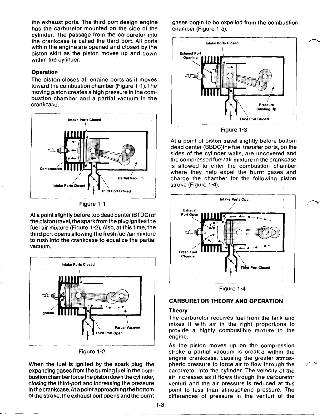
The piston closes all engine ports as it moves
toward the combustion chamber (Figure 1-1). The
moving piston creates a high pressure in the combustion chamber and a partial vacuum in the
crankcase.
Intake Ports Closed
Co
gases begin to be expelled from the combustion
chamber (Figure 1-3).
__-
Intake Ports Closed
Exhaust Port
~
Figure
--l_____m_
I
Third
Port Closed
1-3
At a point of piston travel slightly before bottom
dead center (BBDC)
the
fuel transfer ports, on the
sides of the cylinder walls, are uncovered and
the compressed fuel/air mixture in the crankcase
-is allowed to enter the combustion chamber
where they help expel the burnt gases and
charge the chamber for the following piston
stroke (Figure 1-4).
Figure 1-1
At
a point slightly before top dead center (BTDC) of
the piston travel, from the plug ignitesthe
fuel air mixture (Figure 1-2). Also, at this time, the
third port opens allowing the fresh fuel/air mixture
to rush into the crankcase to equalize the partial
vacuum.
Intake Ports Closed
\
Figure 1-2
When the fuel is ignited by the spark plug, the
expanding gases from the burning fuel in the combustion chamber force the piston down thecylinder,
closing the third-port and increasing the pressure
in the
crankcase. At
of the stroke, the exhaust port opens and the burnt
a point approaching the bottom
Intake Ports
Exhaust
Change
Open
__-__
Figure 1-4
CARBURETOR THEORY AND OPERATION
Theory
The carburetor receives fuel from the tank and
it
mixes
with air in the right proportions to
provide a highly combustible mixture to the
engine.
As the piston moves up on the compression
stroke a partial vacuum is created within the
engine crankcase, causing the greater atmospheric pressure to force air to flow through the
carburetor into the cylinder. The velocity of the
air increases as it flows through the carburetor
venturi and the air pressure is reduced at this
point to less than atmospheric pressure. The
differences of pressure in the venturi of the
1-3
Page 8
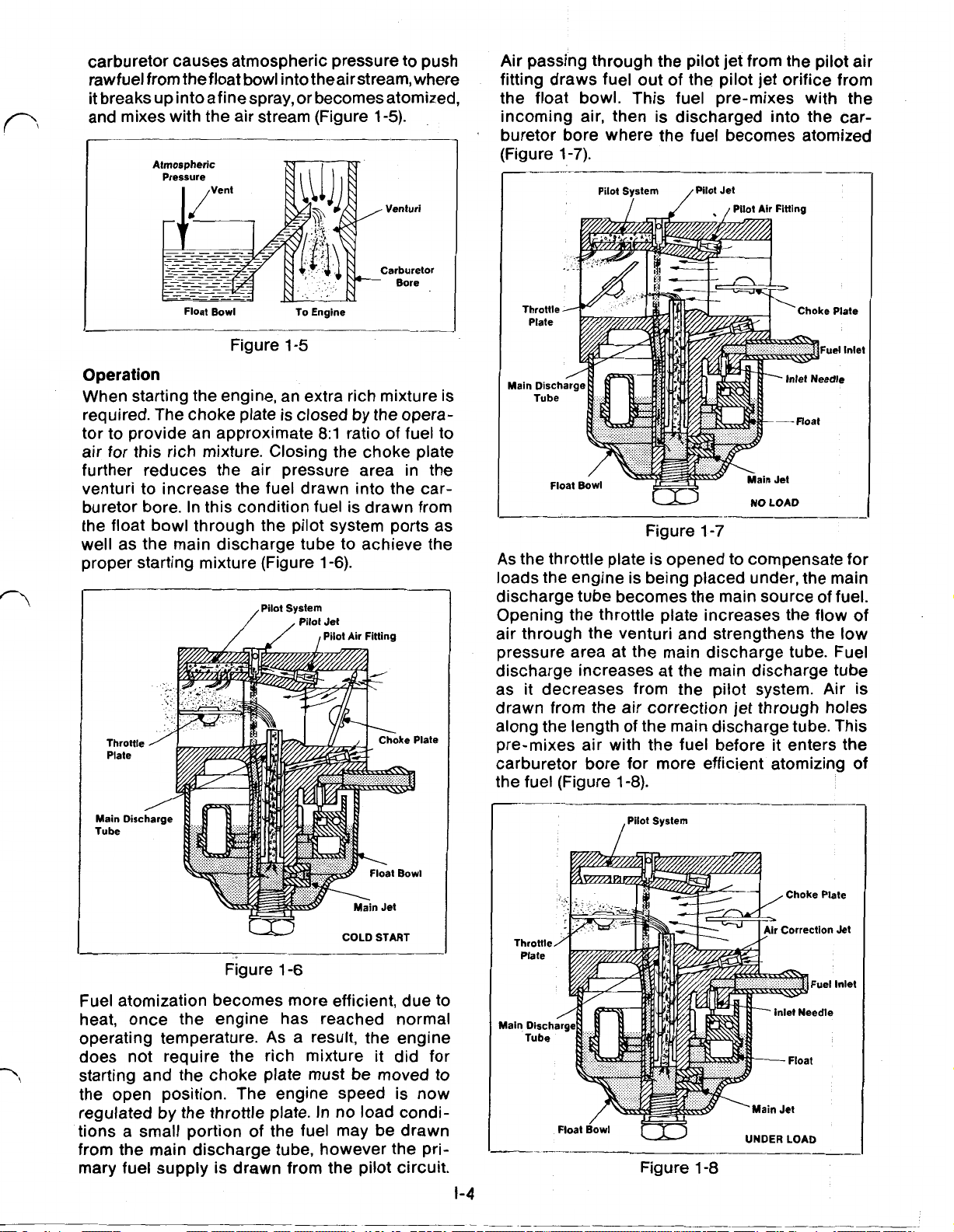
carburetor causes atmospheric pressure to push
rawfuel from the
bowl into theair
stream, where
float
it breaks up into a fine spray, or becomes atomized,
and mixes with the air stream (Figure
1-5).
Air passing through the pilot jet from the pilot air
fitting draws fuel out of the pilot jet orifice from
the float bowl. This fuel pre-mixes with the
incoming air, then is discharged into the carburetor bore where the fuel becomes atomized
Float
Bowl
(Figure
To Engine
1-7).
Figure
1-5
Operation
When starting the engine, an extra rich mixture is
required. The choke plate is closed by the opera-
tor to provide an approximate
8:1
ratio of fuel to
air for this rich mixture. Closing the choke plate
further reduces the air pressure area in the
venturi to increase the fuel drawn into the car-
buretor bore. In this condition fuel is drawn from
the float bowl through the pilot system ports as
well as the main discharge tube to achieve the
proper starting mixture (Figure
Pilot System
1-6).
Pilot
Jet
Pilot Air Fitting
NO
LOAD
Figure
As
the throttle plate is opened to compensate for
1-7
loads the engine is being placed under, the main
discharge tube becomes the main source of fuel.
Opening the throttle plate increases the flow of
air through the venturi and strengthens the low
pressure area at the main discharge tube. Fuel
discharge increases at the main discharge tube
as
it
decreases from the pilot system. Air
is
drawn from the air correction jet through holes
along the length of the main discharge tube. This
pre-mixes air with the fuel before it enters the
carburetor bore for more efficient atomizing of
:he fuel (Figure
1-8).
COLD START
Figure
1-6
Fuel atomization becomes more efficient, due to
heat, once the engine has reached normal
operating temperature.
As
a result, the engine
does not require the rich mixture it did for
starting and the choke plate must be moved
to
the open position. The engine speed is now
regulated by the throttle plate. In no load condi-
tions a small portion of the fuel may be drawn
from the main discharge tube, however the pri-
mary fuel supply is drawn from the pilot circuit.
1-4
Float
Bowl
/pilot
System
Figure
UNDER LOAD
1-8
Page 9
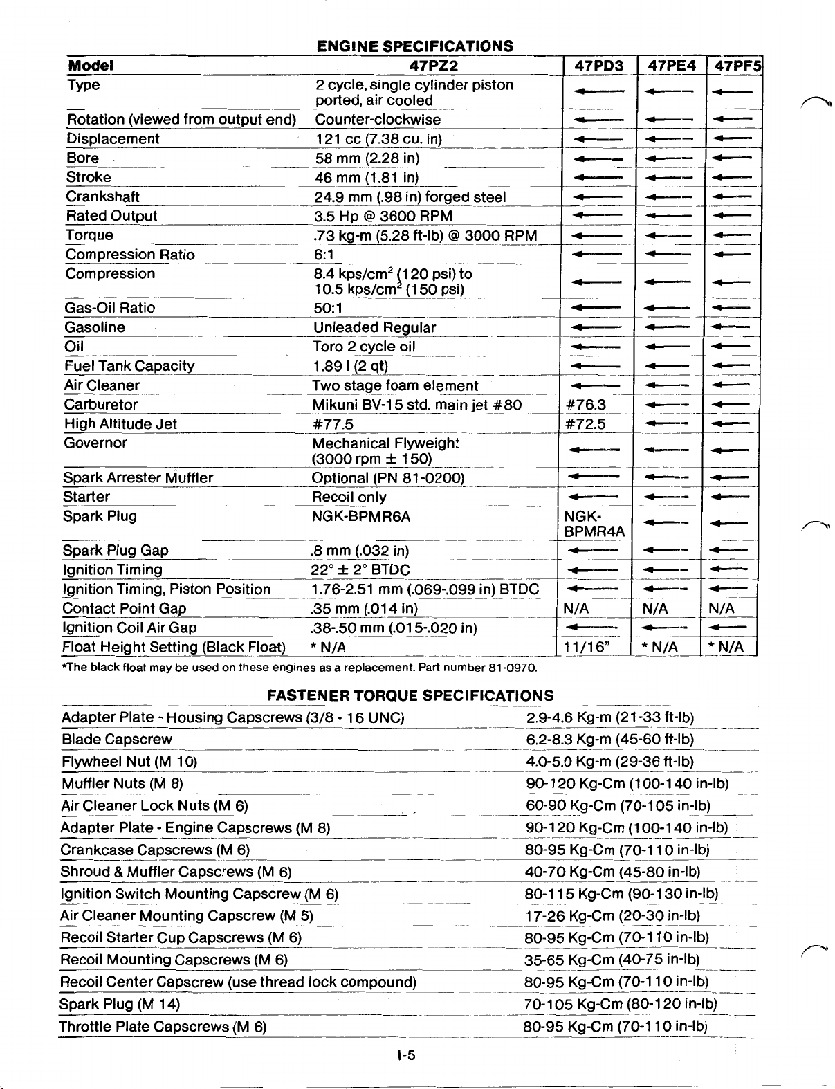
ENGINE SPECIFICATIONS
Model
~---
47P22
Type 2 cycle, single cylinder piston
ported, air cooled
Rotation (viewed from output end) Counter-clockwise
Displacement 121 cc (7.38 cu. in)
Bore 58 mm (2.28 in)
Stroke 46 mm (1.81 in)
Crankshaft 24.9 mm (.98in) forged steel
Rated Output
Torque .73 kg-m (5.28 ft-lb)
3.5
Hp @ 3600 RPM
@
3000
Compression Ratio 6: 1
Compression
Gas-Oil Ratio
8.4kps/cm2 20 psi) to
50
10.5 kps/cm (1
50:
1
psi)
Gasoline Unleaded Regular
TTO
Oil 2 cycle oil
Fuel Tank Capacity
Air Cleaner
Carburetor Mikuni
High Altitude Jet
Governor Mechanical Flyweight
-~
1.89
I
(2 qt)
Two stage foam element
BV-15std.
main jet #80
#77.5
~-
RPM
--
47PD3
#76.3
#72.5
Spark Arrester Muffler Optional (PN 81-0200)
Starter Recoil only
Spark Plug NGK-BPMR6A
~-
NGKBPMR4A
Ignition Timing 22" 2" BTDC
Ignition Timing, Piston Position 1.76-2.51mm (.069-.099in) BTDC
Contact Point Gap .35 mm (.014in)
~-
N/A
Ignition Coil Air Gap .38-.50 mm (.015-.020in)
Float Height Setting (Black Float)
*The black float may be used on these engines as a replacement. Part number
*
N/A
.
11/16"
81-0970.
*
N/A
FASTENER TORQUE SPECIFICATIONS
Adapter Plate Housing Capscrews (3/8-16UNC) 2.9-4.6 Kg-m (21
-33
ft-lb)
Blade Capscrew 6.2-8.3 Kg-m (45-60 ft-lb)
Flywheel Nut (M 10) 4.0-5.0 Kg-m (29-36 ft-lb)
Muffler Nuts (M 8)
Air Cleaner Lock Nuts (M 6)
Adapter Plate Engine Capscrews (M 8)
90-120Kg-Cm (100-140 in-lb)
60-90 Kg-Cm (70-1
05
.
in-lb)
90-120Kg-Cm (100-140in-lb)
Crankcase Capscrews (M 6) 80-95 Kg-Cm (70-1 10 in-lb)
&
Shroud
Ignition Switch Mounting Capscrew (M 6) 80-1 15 Kg-Cm (90-1
Air Cleaner Mounting Capscrew (M
Muffler Capscrews (M 6)
-..-
5)
40-70 Kg-Cm (45-80 in-lb)
30
in-lb)
17-26 Kg-Cm (20-30 in-lb)
Recoil Starter Cup Capscrews (M 6) 80-95 Kg-Cm (70-1 10 in-lb)
Recoil Mounting Capscrews (M 6) 35-65 Kg-Cm (40-75 in-lb)
Recoil Center Capscrew (use thread lock compound) 80-95 Kg-Cm (70-1 10 in-lb)
05
Spark Plug (M 14) 70-1
__-
Kg-Cm (80-1 20 in-lb)
Throttle Plate Capscrews (M 6) 80-95 Kg-Cm (70-1 10 in-lb)
.-
1-5
Page 10

SPECIAL TOOLS LIST
ITEM
1
2
3
4
5
6
7
8.
9
10
11
12
13
14
15
16
17
18
19
20
21
22
Flywheel Puller..
Starter Cup Wrench
Timing Tester..
Spark Tester
Continuity Light
Tachometer..
Ohmmeter (Multimeter).
Feeler Gauges
Micrometer.
Spark Plug Gapping Tool
Compression Gauge..
Threebond#1104 (Loctite#515).
Loctite
Timing Dial Indicator..
Dial Indicator..
Cylinder Gauge Set..
Spark Plug Socket..
Coil Gauge
Torque Wrench (ft-lb)
Torque Wrench (in-lb).
Magnetic
Dial Indicator Stand
DESCRIPTION
..................................
................................
....................................
......................................
...................................
..
.................................
...........................
....................................
.......................................
..........................
.............................
.................
#242
(Threebond#1342).
.................
.............................
....................................
..............................
...............................
.38-.50mm
(.015-.020 in)
..............................
.............................
“V”
Blocks..
.............................
...............................
...............
PART
41-7650
45-1 390
41 -7900
41 -7890
36-4050
42-2730
505-80
505-76
NO.
Page 11
SPARK PLUG
CAUTION: To reduce poten-
tial accidents, never perform
an adjustment or maintenance procedure while the engine is running. Pull
off
the high tension wire
the spark plug
to prevent an accidental start.
Many times an inspection of the spark plug can
determine whether the engine is functioning
properly. A spark plug which is functioning
normally will show slight electrode wear with
brown
black carbon fouled plugs are caused by a rich
carburetor mixture, weak spark, or improper
gasoline to oil mixture. Excessively worn elec-
trodes or a blistered insulator indicate spark plug
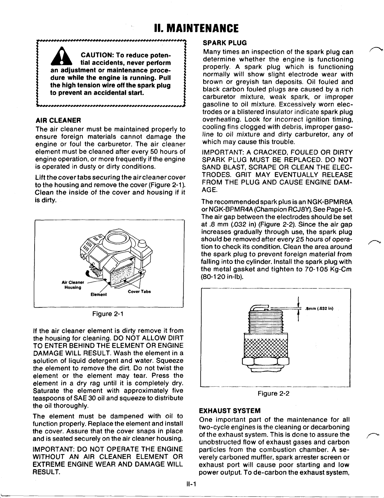
AIR
CLEANER
The air cleaner must be maintained properly to
ensure foreign materials cannot damage the
engine
element must be cleaned after every
engine operation, or more frequently
is operated in dusty
or
foul the carburetor. The air cleaner
50
hours of
if
the engine
or
dirty conditions.
Lift the cover tabs securing the air cleaner cover
to the housing and remove the cover (Figure 2-1).
Clean the inside
is
dirty.
of
the cover and housing if it
overheating. Look for incorrect ignition timing,
cooling fins clogged with debris, improper gasoline to oil mixture and dirty carburetor, any of
which may cause this trouble.
IMPORTANT:
SPARK PLUG MUST BE REPLACED. DO NOT
SAND BLAST, SCRAPE OR CLEAN
TRODES. GRIT MAY EVENTUALLY RELEASE
FROM THE PLUG AND CAUSE ENGINE DAM-
AGE.
The recommended spark plus is an NGK-BPMRGA
or
NGK-BPMR4A (Champion RCJ8Y). See Page
The air gap between the electrodes should be set
.8
at
increases gradually through use, the spark plug
should be removed after every 25 hours of operation to check its condition. Clean the area around
the spark plug to prevent foreign material from
falling into the cylinder. Install the spark plug with
the metal gasket and tighten to 70-105 Kg-Cm
(80-1 20 in-lb).
or
greyish tan deposits. Oil fouled and
A
CRACKED, FOULED
mm
(.032 in)
(Figure 2-2). Since the air gap
OR
THE
DIRTY
ELEC-
1-5.
Figure 2-1
If the air cleaner element is dirty remove it from
the housing
cleaning.
DO
NOT ALLOW DIRT
for
TO ENTER BEHIND THE ELEMENT OR ENGINE
DAMAGE WILL RESULT. Wash the element in a
solution of liquid detergent and water. Squeeze
the element to remove the dirt. Do not twist the
element or the element may tear. Press the
element in a dry rag until it is completely dry.
Saturate the element with approximately five
teaspoons of SAE
30
oil and squeeze to distribute
the oil thoroughly.
The element must be dampened with oil to
function properly. Replace the element and install
the cover. Assure that the cover snaps in place
and is seated securely on the air cleaner housing.
IMPORTANT: DO NOT OPERATE THE ENGINE
AIR
WITHOUT AN
CLEANER ELEMENT OR
EXTREME ENGINE WEAR AND DAMAGE WILL
RESULT.
(.032
EXHAUST SYSTEM
One important part of the maintenance for all
or
two-cycle engines is the cleaning
de-carboning
of the exhaust system. This is done to assure the
unobstructed flow of exhaust gases and carbon
particles from the combustion chamber.
verely carboned muffler, spark arrester screen or
exhaust port will cause poor starting and
power output. To de-carbon the exhaust system,
11-1
in)
A
se-
low
Page 12

remove the muffler from the engine by removing
the two retaining nuts and the through bolt (Figure
2-3).
Figure 2-3
the loose carbon from the muffler using com-
pressed air. Install the muffler using a new gasket
and attach it with proper fasteners tightened to
the correct torque. See page
1-5.
DECARBONING CYLINDER HEAD
If the exhaust ports and muffler show signs of excessive carbon buildup,
it
may be necessary to
de-carbon the cylinder head. To accomplish this the
entire engine must be disassembled to allow
access into the combustion chamber. (See Disassembly Instructions Page IV-1.) Remove the
carbon deposits from the piston and the cylinder
chamber using a wooden stick. TAKE CARE NOT
TO SCRATCH THE PISTON
CHAMBER AND DO NOT USE A METAL TOOL TO
REMOVE THE DEPOSITS.
OR
CYLINDER
Check the cylinder exhaust port.
If
necessary,
remove the carbon deposits from the port using
a wooden stick. Also clean the small hole next to
the exhaust port. This hole acts as a compression
relief to lessen the force required to start the
If
engine.
plugged, the recoil starter will be hard
to pull (Figure 2-4).
IMPORTANT: WHEN REMOVING CARBON DEPOSITS, ROTATE THE CRANKSHAFT TO
CLOSE THE EXHAUST PORT WITH THE PISTON. THIS WILL PREVENT LOOSE CARBON
DEPOSITS FROM FALLING INTO THE CYLIN-
DER. TAKE CARE NOT TO SCRATCH THE
PISTON AND DO NOT USE
A
METAL TOOL TO
REMOVE THE DEPOSITS.
IGNITION
To check the timing
TIMING
(MODEL
it
is necessary to remove the
47P22
ONLY)
air cleaner to view the flywheel. (See Disassembly
Instructions.) The flywheel has a group of three
raised marks on its outer edge. The center mark
corresponds to BTDC and the others represent
the tolerance of plus or minus 2O.Connect one lead
of the timing tester to the engine frame (ground).
(A
timing tester must be used. An Ohmmeter or continuity light will not indicate the position of the contact points.) Disconnect the wire at the ignition
switch under the fuel tank and connect the other
tester lead to this wire (Figure2-5).Turn theengine
crankshaft in its normal rotation, counter-clockwise
as viewed from the output end. The contact points
should open, as indicated by the timing tester, when
the pointer on thecrankcase housing points to the
Center of the
three
marks on the flywheelcasting.
If
the timing is wrong the flywheel must be removed
and the contact points re-gapped or replaced.
Models 47PD3, 47PE4 and 47PF5 use solid state
ignition systems and have their timing fixed at
BTDC.
Figure 2-4
Before installing the muffler check for cracks and
leaks. Inspect the inlet and outlet for carbon
\
buildup. Remove excessive deposits with a
scraping tool and soak the muffler in solvent to
remove wet oil deposits. Allow to air dry or dry
with compressed air. Remove the muffler heat
shield and tap the muffler body with a plastic
hammer
to
loosen the carbon deposits. Blow all
Figure
2-5
11-2
Page 13

IGNITION TIMING (DIAL INDICATOR)
The ignition timing may be more accurately
checked using a dial indicator. Remove the spark
plug wire and spark plug and insert the dial indicator into the spark plug hole. Rotate the engine
crankshaft until the dial indicator registers the piston at top dead center and “zero” the dial. Connect
one lead of a timing tester to the engine frame.
(A
timing tester must be used. An Ohmmeter or continuity light will not indicate the position of the
con-
tact points.) Disconnect the wire at the ignition
switch under the fuel tank and connect the other
tester lead to this wire (Figure 2-6). Slowly rotate
the crankshaft clockwise, as viewed from the out-
put end, until the tester signals the contact points
are opening.
(.069
in) and 2.51 mm
If
the testersignals between 1.76 mm
(.099
in) of piston travel, as
read on the dial indicator, the engine is properly
timed. If the timing is wrong the flywheel must be
removed and the contact points re-gapped.
installing new or reconditioned contact points
ensure that the wiring is routed through the channel
in the crankcase housing and under the ignition
coil. FAILURE TO ROUTE THE WIRES PROPERLY
MAY ALLOW THE WIRING TO CONTACT THE FLY-
WHEEL
the contact points to
AND
CAUSE A SHORT CIRCUIT. Adjust
.35
mm (.014 in) air gap, using
a feeler gauge, with the cam follower on the high
point of the timing cam (Figure
2-7).
Check the timing using either method previously described. It
may be necessary to readjust the contact point
gap to obtain the timing specification.
Contact Point
Assembly
Figure 2-6
CONTACT POINTS AND CONDENSER
MODEL 47P22 ONLY
The contact points and condenser do wear out
through use and their performance level is
affected by dust, moisture and corrosion. Inspection of these components requires removal of the
flywheel.
(See Disassembly Instructions.) With the flywheel
removed, inspect for wear of the cam follower
and burning or pitting of the contact points. The
surface of the contact points should have a grey,
frosted appearance
if
wearing normally.
If
the
contact points are cratered or have surface
buildup they should be cleaned or replaced. The
contacts can be cleaned with an electrical
sol-
vent and contact point sandpaper. Ensure that all
dust and dirt
is
removed after sanding. Cratering
of the points indicates the condenser may be
faulty. Verify the condition of the condenser
If
through tests with an ignition analyzer.
an
analyzer is not available the condenser must be
be
considered faulty and should
replaced. When
Condenser
Figure
Cam
I
Follower
2-7
IGNITION COIL
Whenever the flywheel is exposed the ignition
coil condition and air gap should be checked.
for
Inspect the ignition coil
a cracked casing, loose
laminations, damaged wires and over heating. The
ignition coil air gap is
.38-50
mm (.015-.020 in).
A
non-metallic flexible gauge such as shown in the
Special Tools Section should be used. To adjust,
rotate the flywheel magnets away from the ignition coil and loosen the two ignition coil retaining
capscrews. Insert the gauge between the coil
laminations and the flywheel (Figure 2-8).Tighten
the retaining capscrews to hold the adjustment.
Figure
2-8
11-3
Page 14

The ignition coil contains two separate windings
inside the coil casing (Figure 2-9). Use an Ohmmeter to check the resistance levels of each winding. To check the primary winding, disconnect the
ignition switch wire and connect the positive lead
of the Ohmmeter to the ignition coil lead. Connect
the negative lead to the engine frame (ground).
primary winding resistance is ohms
The
(Rxl
scale). To check the secondary winding, disconnect
the high tension wire at the spark plug. Connect
the positive lead of the Ohmmeter to the high tension wire. Connect the negative lead to the engine
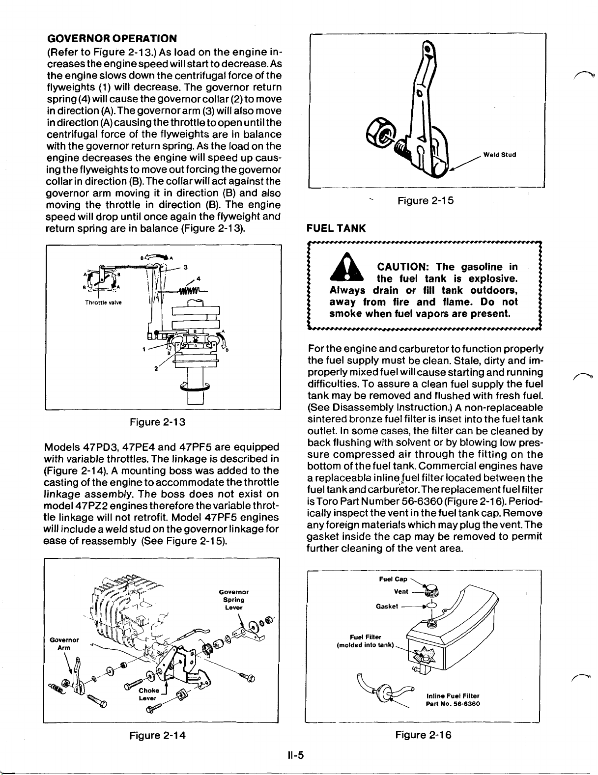
GOVERNOR
The governor linkage is factory preset to regu-
late the engine speed at
Check the adjustment of the governor
engine is suspected of improper speed. To gain
access to the governor linkage removal of the
air cleaner is recommended. (See Disassembly
Instructions.) Before adjusting the governor,
inspect the control linkage for bent, broken and
worn parts. Loosen the governor arm clamping
bolt and use a screwdriver to spread the governor arm clamp (Figure 2-1 1).
frame (ground). The secondary coil resistance
should be 5800-7940 ohms
ignition coil must be replaced
(Rxl
000
if
the resistance
scale). The
levels are incorrect.
3000
150 RPM.
if
the
Ignition Switch Wire
Primary
Coil
ohms
Ground
High Tension Wire
\
Secondary
5800-7940
(R
x
1000
Model
47P22
Coil
ohms
scale)
Figure 2-9
The ignition coil used on models 47PD3, 47PE4,
and 47PF5 consists of the main coil, high tension
wire and ignition kill wire (See Figure 2-1
Testing of the coil may becompleted with a
0).
Graham
Lee ignition tester model number 31-SMXH. In-
structions for testing are included with the tester.
Figure 2-1 1
Adjust the governor by holding the governor
lever to the right while turning the governor shaft
to the right. Hold the adjustment and tighten the
clamp bolt (Figure 2-1 2).
High Tension
Wi
Figure 2-1
0
Figure 2-1
2
Connect the return spring to the center hole in
the governor spring bracket. The center hole
should govern the engine speed at the recom-
mended
engine speed 150
3000
RPM. The top hole will raise the
RPM
and the bottom hole will
lower the engine speed 150 RPM. Engine speed
can be verified using a tachometer such as listed
in the Special Tools Section. (See page
II
-4
1-6).
Page 15
GOVERNOR
OPERATION
(Refer to Figure 2-1 3.) As load on the engine increases the enginespeed will start to
decrease. As
the engine slows down the centrifugal force of the
flyweights (1) will decrease. The governor return
spring (4) will cause the governor collar (2) to move
in direction (A).
in direction (A) causing the throttle to
centrifugal force
The
governorarm (3) will also move
open
of
the flyweights are in balance
until the
with the governor return spring. As the load on the
engine decreases the engine will speed up causing the flyweights to move out forcing the governor
collar in direction (B).
The
collar will act against the
governor arm moving it in direction (B) and also
moving the throttle in direction
(B).
The engine
speed will drop until once again the flyweight and
return spring are in balance (Figure 2-1 3).
FUEL
TANK
Figure 2-1
5
1
Figure 2-1
3
Models 47PD3,47PE4 and 47PF5 are equipped
with variable throttles. The linkage is described in
(Figure 2-1 4).
A
mounting boss was added to the
casting of the engine to accommodate the throttle
linkage assembly. The boss does not exist on
model 47PZ2 engines therefore thevariable throt-
tle linkage will not retrofit. Model 47PF5 engines
will include a weld stud on the governor linkage for
ease of reassembly (See Figure 2-1
5).
CAUTION:
!
the fuel tank is explosive.
Always drain or
away from fire and flame.
The gasoline in
fill
tank outdoors,
Do
not
smoke when fuel vapors are present.
For the engine and carburetor to function properly
the fuel supply must be clean. Stale, dirty and im-
properly mixed fuel will cause starting and running
difficulties. To assure a clean fuel supply the fuel
tank may be removed and flushed with fresh fuel.
A
(See Disassembly Instruction.)
non-replaceable
sintered bronze fuel filter is inset into the fuel tank
outlet. In some cases, the filter can be cleaned by
back flushing with solvent or by blowing low pressure compressed air through the fitting on the
bottom of the fuel tank. Commercial engines have
a replaceable inline fuel filter located between the
fuel tank
and carburetor. The
replacementfuel filter
is Toro Part Number 56-6360 (Figure 2-1 6). Periodically inspect the vent in the fuel tank cap. Remove
any foreign materials which may plug the
vent. The
gasket inside the cap may be removed to permit
further cleaning of the vent area.
Governor
Arm
Figure 2-1 4
Governor
Spring
11-5
Fuel
Fuel
Filter
(molded into lank).
Cap
Inline
Part
No.
Figure 2-1 6
Fuel Filter
56-6360
Page 16
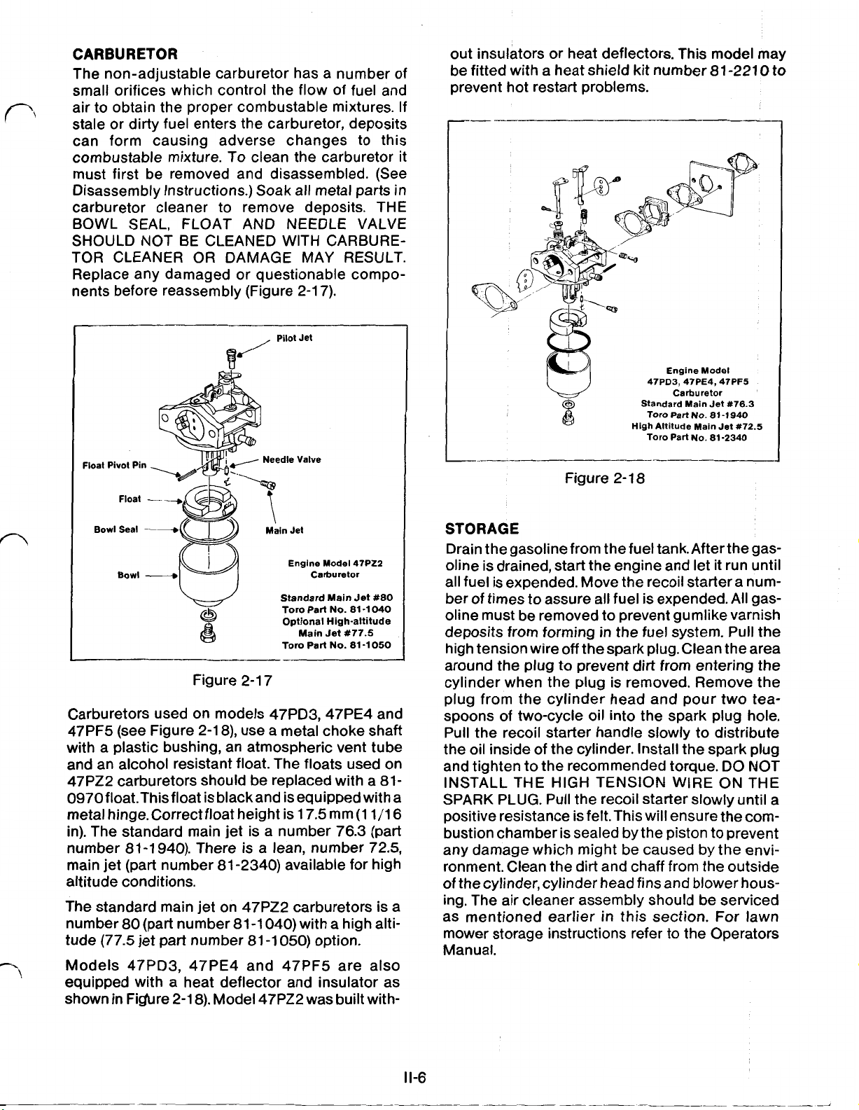
CARBURETOR
The non-adjustable carburetor has a number of
small orifices which control the flow of fuel and
air to obtain the proper combustable mixtures.
stale or dirty fuel enters the carburetor, deposits
can form causing adverse changes to this
cornbustable mixture. To clean the carburetor it
must first be removed and disassembled. (See
Disassembly Instructions.) Soak all metal parts in
carburetor cleaner to remove deposits. THE
BOWL SEAL, FLOAT
AND
NEEDLE VALVE
SHOULD NOT BE CLEANED WITH CARBURETOR CLEANER
OR
DAMAGE MAY RESULT.
Replace any damaged or questionable compo-
nents before reassembly (Figure 2-1 7).
Pilot Jet
Float Pivot Pin
Needle Valve
If
out insulators or heat deflectors. This model may
be fitted with a heat shield kit number 81 -221
0
to
prevent hot restart problems.
Engine Model
47PD3,47PE4,47PF5
Carburetor
Standard Main Jet
Toro
Part
No.
Part
No.
81-1940
81-2340
Figure
High Altitude Main Jet
Toro
2-
18
Bowl
Seal
Bowl
Engine Model 47P22
Carburetor
Standard Main Jet
Toro
Part
Main
Part
No.
Jet
No.
Optional High-altitude
Tor0
#80
81-1040
#77.5
81 -1
050
Figure 2-1 7
Carburetors used on models 47PD3,47PE4 and
47PF5 (see Figure 2-1 8), use a metal choke shaft
with a plastic bushing, an atmospheric vent tube
and an alcohol resistant float. The floats used on
47PZ2 carburetors should be replaced with a 810970
float.
This
float is black
and
is equipped with a
metal hinge. Correct float height is 17.5 mm (1 1 /16
in). The standard main jet is a number 76.3 (part
number 81-1 940). There is a lean, number 72.5,
main jet (part number 81 -2340) available for high
altitude conditions.
The standard main jet on 47PZ2 carburetors is a
number
tude (77.5 jet part number 81 -1
80
(part number 81 -1 040) with a high alti-
050)
option.
Models 47PD3, 47PE4 and 47PF5 are also
equipped with a heat deflector and insulator as
shown in Figure 2-1 8). Model 47PZ2 was built with-
STORAGE
Drain the gasoline
oline is drained, start the engine and let
from
the
fuel
tank.
After the gas-
it
run until
all fuel is expended. Move the recoil starter a number of times to assure
all
fuel is expended.
All
gasoline must be removed to prevent gumlike varnish
deposits from forming in the fuel system. Pull the
off
high tension wire
the spark plug. Clean the area
around the plug to prevent dirt from entering the
cylinder when the plug is removed. Remove the
plug from the cylinder head and pour two teaspoons of two-cycle oil into the spark plug hole.
Pull the recoil starter handle slowly to distribute
the oil inside of the cylinder. Install the spark plug
and tighten to the recommended torque. DO NOT
INSTALL THE HIGH TENSION WIRE
ON
THE
SPARK PLUG. Pull the recoil starter slowly until a
positive resistance is felt. This will ensure the combustion chamber is sealed by
the
piston to prevent
any damage which might be caused by the environment. Clean the dirt and chaff from the outside
of
the cylinder, cylinder head fins and blower hous-
ing. The air cleaner assembly should be serviced
as mentioned earlier in this section. For lawn
mower storage instructions refer to the Operators
Manual.
Page 17
111.
TROUBLESHOOTING AND TEST PROCEDURES
Generally all gasoline-powered products require
some form of service
time. The amount of time and expense involved
in repairing a product can be greatly impacted
by the amount of time required to initially determine the cause of the difficulty. Therefore, it is
recommended to make these preliminary checks
before proceeding to secondary troubleshooting
procedures.
PRELIMINARY TROUBLESHOOTING
Ignition System
1. Check the ignition switch and wiring
2.
Ensure the spark plug is the correct type
3.
Check the spark plug for the correct gap,
damaged and excessively carboned
electrodes
4.
Check the spark intensity.
Fuel System
1.
Check the choke position and controls
2.
Check the throttle (if
nor mechanism
3. Ensure the fuel is fresh, clean and of the
proper gas-oil mixture
4.
Check the fuel filter.
Air Cleaner
1. Check for housing and element damage
2.
Check for dirty element
3.
Check for too much
element
Compression
1.
Check the cylinder compression. (Refer to
page
111-2)
Crankcase
1. Ensure the crankcase is sealed. (Refer to
I11-3)
page
Spark Intensity
The ignition system can be checked
tensity using the spark tester listed in the Special
Tools Section of this manual (Figure
or
repair during their life-
or
so
equipped) and gover-
or
too little oil in the
for
spark in-
3-1).
burnt
1. Pull
2.
3. Check for the correct spark plug gap and
4.
5.
6.
ENGINE
As a safety measure the engine is designed to
stop within three seconds after the control bar is
released. Release of the control bar grounds the
magneto through the ignition switch to prevent
ignition and allows the spring activated brake
pad to engage the flywheel.
The engine brake and ignition switch are controlled by one common control cable activated
by the control bar on the mower handle. To start
the engine the control bar is raised and held
against the handle. This pulls the brake pad
away from the flywheel and simultaneously depresses the plunger on the ignition switch.
THE ENGiNE BRAKE SYSTEM SHOULD
MAINTAINED
TION
the engine brake and ignition switch:
off
the spark plug connector and remove
the spark plug.
Inspect the spark plug for wear, carbon
deposits and damage. (See Maintenance
if
Section) Replace the plug
or
fouled.
adjust,
bending the outer electrode. Do not pry
against the inner electrode
may be damaged.
Attach the spark tester as shown and verify
the tester gap is set at
Pull the starter and observe for spark. THE
SPARK MAY BE DIFFICULT TO SEE
WELL LIGHTED AREAS.
A
been spilled or inflammable vapors may
exist.
If
shooting chart. (Page
OR
if
necessary, to
CAUTION:
spark where gasoline has
A
fire could result.
no spark is viewed, refer to the trouble-
111-4)
BRAKE
INJURY MAY RESULT. To troubleshoot
AND IGNITION SWITCH
IN
PROPER WORKING CONDI-
damaged, burnt,
.8
mm
or
the insulator
4.2
mm (.166 in).
Do
not test for
(.032
in) by
IN
BE
Figure
3-1
1. Remove the fuel tank for ease of inspection.
(See Disassembly Instructions page IV-1).
2.
Ensure that the brake spring forces the brake
pad against the flywheel when the control
bar is in the ‘STOP” position and that the pad
clears the flywheel when the control bar is in
the ‘START” position.
111-1
Page 18
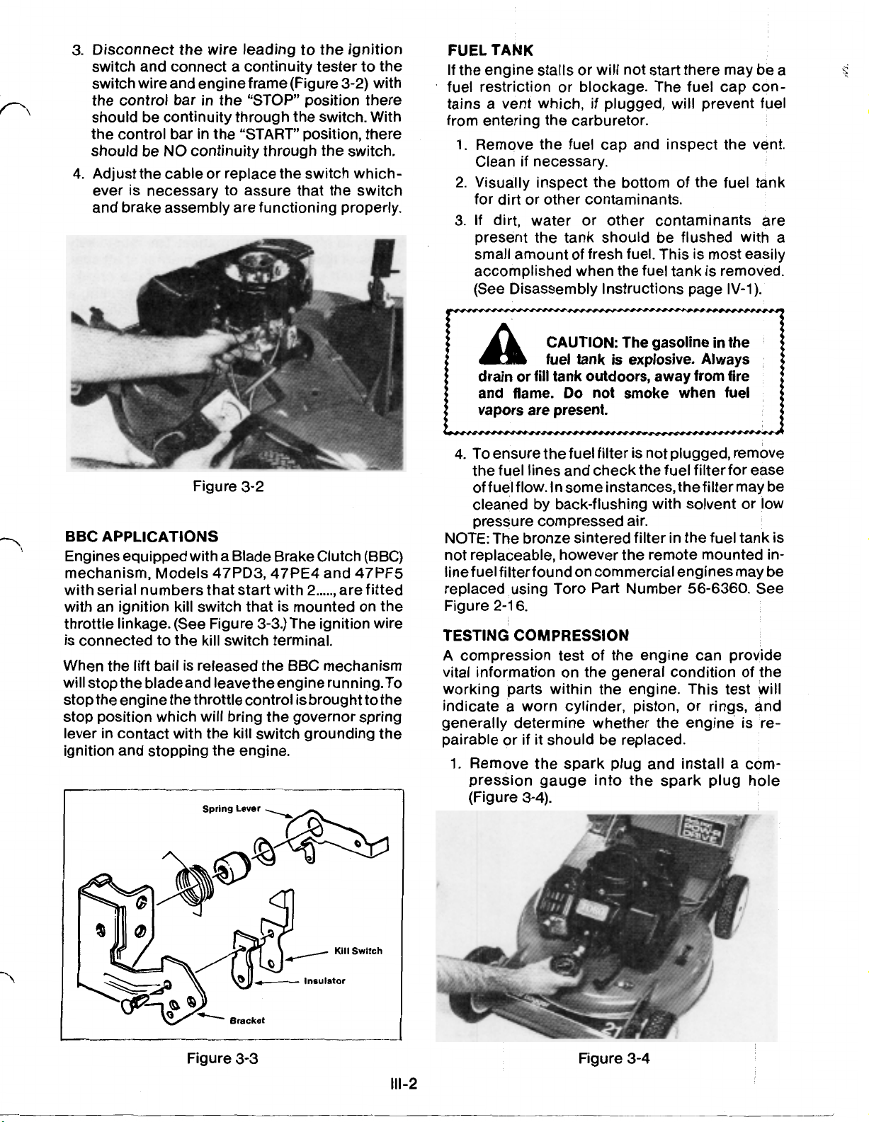
Disconnect
3.
switch and connect a continuity tester to the
switch wire and engine frame (Figure
the control bar in the
should be continuity through the switch. With
the control bar in the “START” position, there
should be
4.
Adjust the cable
ever is necessary to assure that the switch
and brake assembly are functioning properly.
BBC
APPLICATIONS
Engines equipped with a Blade Brake Clutch (BBC)
mechanism, Models 47PD3,47PE4 and 47PF5
with serial numbers that start with
with an ignition kill switch that is mounted on the
throttle linkage. (See Figure
is connected to the kill switch terminal.
When the lift bail is released the BBC mechanism
will stop the blade and leave the engine running. To
stop the engine the throttle control is brought to the
stop position which will bring the governor spring
lever in contact with the kill switch grounding the
ignition and stopping the engine.
I
the
wire leading to the ignition
“STOP”
NO
continuity through the switch.
or
replace the switch which-
Figure
3-2
position there
2.....,
3-3.)
The ignition wire
Spring
Lever
3-2)
with
are fitted
FUEL TANK
If
the engine stalls or will not start there may be a
fuel restriction or blockage. The fuel cap contains a vent which,
from entering the carburetor.
Remove the fuel cap and inspect the vent.
1.
if
Clean
Visually inspect the bottom of the fuel tank
2.
for dirt or other contaminants.
If
3.
present the tank should be flushed with a
small amount of fresh fuel. This is most easily
accomplished when the fuel tank is removed.
(See Disassembly Instructions page
a
drain
and flame.
vapors are present.
4. To ensure the fuel filter is not plugged, remove
the fuel lines and check the fuel filter for ease
necessary.
dirt, water
CAUTION: The gasoline in the
fuel tank
or
fill
if
plugged, will prevent fuel
or
other contaminants are
is
explosive. Always
tank outdoors, away from fire
Do
not smoke when fuel
of fuel flow. In some instances, the filter may be
cleaned by back-flushing with solvent or low
pressure compressed air.
NOTE:
not replaceable, however the remote mounted inline fuel filter found on commercial engines may be
replaced using Toro Part Number 56-6360. See
Figure
TESTING COMPRESSION
A
vital information on the general condition of the
working parts within the engine. This test will
indicate a worn cylinder, piston,
generally determine whether the engine is repairable
I
The bronze sintered filter in the fuel tank is
2-1
6.
compression test of the engine can provide
or
or
if
it should be replaced.
1.
Remove the spark plug and install a compression gauge into the spark plug hole
(Figure 3-4).
IV-1).
rings, and
Figure
Bracket
3-3
Kill
Switch
Figure 3-4
111-2
Page 19

2.
Pull the starter rope rapidly several times
until the compression reading on the gauge
stabilizes.
3.
If
thecompression reading is below
(92
psi),
cylinder,
be suspected.
kps-cm2
(1
20
piston or ring damage should
A
new engine should have
psi)
1
0.5
kps-cm2
(1
6.5
50
psi).
kps-cm2
8.4
An engine with low compression must be disassembled and inspected for damage of the
internal components. (See Disassembly Instructions.) Check all components to the specifications listed in the Service Data Section of this
manual. Replace all parts which fall outside of
these specifications. The engine contains a cast
iron cylinder liner, which is not replaceable.
Special factory processes are required to install
this liner.
CRANKCASE
The engine relies on a tightly sealed crankcase
in order to function properly. The downward
movement of the piston causes the crankcase to
be pressurized. This pressure is required to
expell the exhaust gases from the combustion
chamber and to supply a fresh fuel mixture for
the compression stroke. The upward movement
of the piston on the compression stroke creates
a vacuum to draw fresh fuel into the crankcase.
In both instances a tightly sealed crankcase is
the key to efficient performance. The most likely
places of leakage are at the governor shaft seal,
crankshaft seals and at the seam of the crankcase halves. The simplest means
of
detecting a
crankcase leak is to check for wet, oily deposits
around the seal areas.
111-3
Page 20
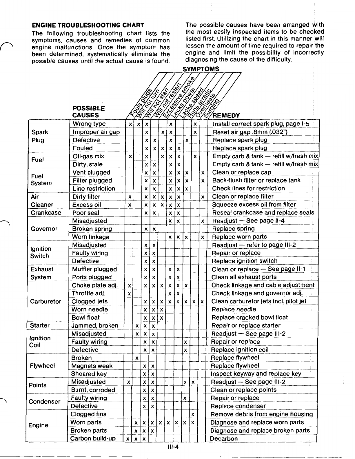
ENGINE TROUBLESHOOTING CHART
The following troubleshooting chart lists the
symptoms, causes and remedies of common
engine malfunctions. Once the symptom
been determined, systematically eliminate the
possible causes until the actual cause is found.
The possible causes have been arranged with
the most easily inspected items to be checked
listed first. Utilizing the chart in this manner
Of
lessen the amount
engine and limit the possibility
diagnosing
the
cause of
time required to repair the
Of
incorrectly
the
difficulty.
SYMPTOMS
Will
Install correct spark plug, page
1-5
Reset air gap .8mm (.032")
Replace spark plug
__-
Replace spark plug
Empty carb
&
tank refill w/fresh
Empty carb &tank refill w/fresh mi)
Clean or replace cap
__-
Check lines for restriction
Clean
Squeeze excess oil
or
replace filter
from
filter
Reseal crankcase and replace seals
Readjust See page
Readjust refer
11-4
to
page 111-2
Replace ignition switch
Clean
replace See page
11-1
or
Clean all exhaust ports
Check linkage and cable adjustment
Check linkage and governor adj.
111-4
Replace needle
____-._-
Replace cracked bowl float
Repair or replace starter
Repair or replace
_-
Replace ignition coil
Replace flywheel
d replace worn parts
Diagnose and replace broken parts
Page 21

IV.
ENGINE
REMOVAL,
DISASSEMBLY
ASSEMBLY AND
REPAIR
ENGINE REMOVAL
To remove the engine from the mower the air
cleaner housing, recoil assembly and fuel tank
must first be removed to disconnect the control
cables. Remove the retaining capscrew, lockwasher, blade, blade adapter and self-propel
components below the mower deck from the
engine crankshaft. Remove the four capscrews
that retain the engine to the mower chassis and
remove the engine from the mower. The engine
can then be placed in a support fixture for repair.
Most common repairs, however, can be accom-
plished with the engine in place on the mower
chassis. Use the following procedures to dis-
assemble the engine on the mower chassis:
ENGINE DISASSEMBLY AND REPAIR
1. Remove the high tension wire from the spark
plug and drain the fuel from the fuel tank.
INSTRUCTIONS
iS
Center Spring Pawl Spring
Center Spring Pawl Spring
/-
Pawl Retainer-
Pawl Retainer-
Figure
4-1
CAUTION: The gasoline in
A
Always drain
away from fire and flame. Do not
smoke when fuel vapors are present.
2. Remove the four retaining capscrews from
the recoil starter and
engine. Disconnect the recoil rope from the
rope handle stop for ease of handling.
RECOIL STARTER REPAIR
A.
Remove the center capscrew from the
recoil assembly and lift
tainer. Remove the center spring, pawl
and pawl spring. Lift the rope pulley
assembly from the recoil housing and
remove the recoil spring and retainer
(Figure 4-1).
B.
Replace all worn or damaged parts before
reassembling. Reassemble the recoil
starter in reverse order. Use Threebond
#1342
the center capscrew during reassembly
and torque to 80-90Kg-Cm
On installation there should be sufficient
spring pretension to hold the recoil rope
taut in the rope pulley.
NOTE: Place a small amount of #2 grease on the
recoil spring to prevent rust and corrosion.
the fuel tank
or
or Loctite #242 on the threads of
is
explosive.
fill
tank outdoors,
lift
the starter from the
off
the pawl re-.
(70-1
10 in-lb).
IV-
3.
Disconnect the fuel line from the carburetor.
Remove the fuel tank by lifting it from the
mounting tabs of the blower housing.
4.
Remove the capscrew, two nuts and lock
washers which retain the muffler and remove
the muffler from the engine. The heat shield
may also be removed from the muffler. Discard the muffler gasket and remove any
gasket material remaining on the engine or
muffler.
5.
Lift the retaining tabs of the air cleaner cover
and remove the cover and filter element.
Remove the capscrew, and two locknuts
retaining the air cleaner housing and lift the
housing from the engine.
6.
Remove the remaining three capscrews from
the blower housing and lift the blower hous-
ing from the engine.
7.
Cage the spring activated engine brake by
compressing and retaining the control bar
against the operating handle. Remove the
capscrew holding the ignition switch and
brake assembly in place. Disconnect the
ignition switch from the electrical lead and
remove the switch from the brake assembly.
Slowly lower the control bar to disengage
the brake. The brake assembly may now be
disconnected from the control cable for
repair.
8.
Use a starter cup wrench as shown in the
Special
while loosening the flywheel nut. Hold the
1
Tools
List to hold the starter cup
r-
Page 22
flywheel by hand and remove the three remaining capscrews retaining the starter cup
to the flywheel. (It may be necessary to insert
a screwdriver through the starter cup to hold
the flywheel should the capscrews be extremely tight.)
IMPORTANT: DO NOT DEFORM THE
STARTER CUP OR STARTER ENGAGEMENT DIFFICULTY MAY RESULT.
9.
Use the flywheel Duller listed in the Special
Tools Section to pull the flywheel from the
crankshaft.
IMPORTANT: DO NOT PRY ON THE FLYWHEEL CASTING OR STRIKE THE CRANKSHAFT OR DAMAGE WILL RESULT.
Remove the capscrews retaining the contact
10
point cover and lift the cover from the engine.
Remove the small nut retaining the electrical
wires to the contact point assembly. Remove
the two ignition coil hold down screws and
lift the ignition coil and wire harness from the
engine.
Remove the two screws holding the points
11
and condenser in place and lift the points
and condenser from the engine. Remove the
flywheel key from the crankshaft and slide
the timing cam from the engine. There is a
small locating pin for the cam. Take care
that this pin is not lost.
12.
Loosen the clamping bolt on the governor
lever and pry the clamping section of the
lever apart with a screwdriver. Remove the
lever, control rod and springs from the
engine.
13.
Disconnect the choke cable from the carburetor and slide the carburetor, spacer and
gaskets from the mounting studs.
IMP0RTANT: DO NOTREMOVETHECHOKE
SHAFT SCREW OR THE THREADS MAY BECOME STRIPPED.
CARBURETOR
REPAIR
A. Drain the fuel from the carburetor bowl
by removing the bowl nut, washer and
bowl. The bowl seal may be replaced
using a seal pick
if
fuel leakage is noted
on the carburetor bowl.
B.
One end of the float pivot pin is
purposely deformed to lock the pin into
the casting legs. Visually determine
which end is deformed and drive the pin
from the opposite end. Remove the pivot
pin, float, needle valve and spring
from
retainer
the assembly.
C. The main jet and the pilot circuit jet can
be removed for inspection using a flat
blade screwdriver.
so
IMPORTANT:
ABLE. DISASSEMBLY
CHOKE PLATES
NO
OTHER
OF
IS
NOT
PARTS ARE
THE THROTTLE AND
RECOMMENDED.
SCREWS ARE FACTORY TORQUED AND
LOCKED IN PLACE.
IF
NOT PROPERLY REASSEMBLED THE SCREWS MAY LOOSEN AND
CAUSE ENGINE DAMAGE.
D. Reassemble the carburetor in reverse
order. The carburetor and work area
should be clean to prevent contamination
entering the small orifices in the carburetor body.
14.
Remove the retaining capscrew, lockwasher,
anti-scalp cup
if
applicable, blade, blade
adapter, and self-propel components from
the crankshaft. Remove the four capscrews
retaining the engine to the mower chassis
and lift the engine from the mower.
15.
To gain access to the components inside the
crankcase remove the four capscrews re-
taining the engine to the mower adapter
plate and remove the adapter plate from the
engine. Remove the six retaining capscrews
holding the two halves of the crankcase
together and separate the crankcase.
16.
Remove the crankshaft and piston as an
assembly. Remove the seals, bearing locating rings, and bearings from each end of the
crankshaft. Slide the governor assembly
from the crankshaft taking care not to lose
the small locating pin for the governor flyweight collar.
17.
To remove the piston from the connecting
rod use a needle nose pliers and remove one
of the wrist pin retainers. Slide the wrist pin
out of the piston far enough to allow the
piston to be removed from the connecting
rod. The needle bearing may be removed
from the connecting rod, however, there are
no further serviceable parts on the crank-
shaft assembly.
IMPORTANT: THE THREE PIECE CRANK-
SHAFT
IS
ASSEMBLED AT THE FACTORY
TO PRECISION TOLERANCES. ATTEMPT-
ING TO DISASSEMBLE THE CRANKSHAFT
FURTHER WILL RESULT IN CRANKSHAFT
DAMAGE.
18.
The wrist pin and piston rings may be removed from the piston for replacement. The
top ring is made of cast iron with a chrome
plating on the outside diameter.
IMPORTANT: USE CAUTION WHEN RE-
MOVING THE RINGS. OVER-STRETCHING
THE RINGS WILL RESULT IN DIFFICULTY
DURING ENGINE REASSEMBLY.
19.
Remove the governor shaft E-ring and flat
washer and slide the governor shaft out of
SERVICE-
THE
IV-2
Page 23

the crankcase. Use a seal pick to remove the
governor shaft seal.
NOTE: The cylinder contains a cast iron sleeve,
however, this sleeve is not replaceable. The
purpose of the sleeve retainer ring is to assist the
manufacturing process and hold the cast iron
sleeve in place to limit engine damage should
the sleeve loosen during operation.
Engine Assembly And Repair
NOTE: Before attempting to reassemble the engine
refer to the Service Data Specifications (page IV-4)
and replace all parts which are outside the recommended values.
1.
Ensure there are no burrs on the governor
shaft which could cause seal damage and
position the governor shaft through the hole
in the crankcase casting. Use a liberal
amount of
#2
grease and install the governor
shaft seal with the lip towards the inside of
the crankcase. Position the flat washer on
the governor shaft against the shaft seal and
install the E-ring.
2.
Install the two piston rings onto the piston.
The chrome surfaced ring should be positioned at the top of the piston. There is a
small letter
‘R”
stamped on the top side of
each piston ring. This letter should face the
top of the piston.
upside down it
If
the piston ring is put in
will
not seat properly in the
ring groove. Lubricate the wrist pin needle
bearing with two-cycle oil and insert into the
connecting rod. Position the piston over the
connecting rod and insert the wrist pin
through the piston, needle bearing and piston rod. Insert the spring retainers to lock the
wrist pin in place.
IMPORTANT: THE ARROW CAST INTO THE
TOP
OF
THE PISTON
MUST
FACE THE
EXHAUST PORT WHEN ASSEMBLED.
3. Lubricate the moving parts and friction surfaces
of
the crankshaft and piston with twocycle oil. Rotate the piston rings until the ring
gap aligns with the locating studs before
attempting to push the piston into the
cylinder. Insert the crankshaft and piston
assembly into the cylinder.
IMP0RTANT:ASSURETHEARROWONTOP
OF THE PISTON FACES EXHAUST PORT
WHEN ASSEMBLED.
4.
Lubricate the large end of the crankshaft
with two-cycle oil and install the sliding
governor collar. Insert the small locating pin
into the crankshaft and slide the flywheel
collar into position. Position the fly weights
on the lip of the governor collar and locate
the control shaft between the collar and the
crankshaft assembly (See Figure 2-1
3
and
4-2). Lubricate the crankshaft bearings with
IV-3
two-cycle
oil
and install onto either end
crankshaft. Insert the bearing locating rings
into the slots of the crankcase housing to
locate the bearings and crankshaft in position.
Removeburrsfromeitherendofthecrankshaft
and slide seals into position. To prevent seal
damage on installation use a small amount of
#2 grease on the inside diameter of the seal.
Both seals should be installed with the lipfac-
ing into the crankcase assembly.
r-
Figure 4-2
5.
Assure both halves of the crankcase are clean
and free of grease and old sealant. Apply a thin
uniform amount of Threebond #1104
tite #515 sealant to the mating surfaces and
position of the crankcase halves together.
6.
There are three different size capscrews on
the model 47PZ2 to hold the crankcase halves
together.(Thecapscrewson
and 47PF5 are all the same length). Starting on
the governor control shaft side install the
medium sized capscrews at either end. Install
one short capscrew and governor spring
bracket in thecenter hole. Install the other
remaining short capscrews into the other side
in the center hole and the hole nearest the
large end
of
the crankshaft. Install the long
capscrew in the remaining hole. Torque all
capscrews evenly
80-95
See Figure 4-3. Position the engine mower
Torque
Capscrews
47P22
to
80-95
Figure 4-3
the47PD3,47PE4
Kg-Cm (70-1
Only
KaCm
(70-1
10
10
in-lb).
of
or
Loc-
in-lb).
the
n
P
two
two
Page 24
adapter plate with the dimple facing the spark
plug end. Install the four retaining capscrews
and torque to the proper specification.
Install the ignition cam and locating pin to the
7.
flywheel end of the crankshaft. Install the condenser and points in position. Rotate the
shaft until the cam follower is on the high point
of the cam. Adjust the point gap using a feeler
gauge of the appropriate size to set the air gap
at
.35
mm (.014 in). (47PZ2 engine only.)
Install the ignition coil loosely on the mount-
8.
ing posts. Connect the double lead to the
contact point assembly (47PZ2 engine only),
making sure the wires are routed between
the ignition coil mounting posts. The single
lead should be routed along side of the
crankcase housing through the hole in the
casting. The ignition coil air gap setting will
be adjusted later.
Place the gasket, spacer and the second gas-
9.
ket over the mounting studs of the carburetor.
2-18
See Figure
for correct gasket and spacer
placement. Slide the carburetor onto the
mounting studs. Assemble the governor con-
trol lever, linkage and springs to the governor
shaft and the carburetor throttle plate. Move
the governor shaft to the right and rotate the
governor shaft to the right. Tighten the clamp
bolt to hold the adjustment.
Install the contact point cover (47PZ2 engine
10.
only), flywheel key and flywheel to the crankshaft. Install thestartercupwith thecapscrews
and torque to
80-90
Kg-Cm (70-1 10 in-lb). Use
the starter cup wrench to hold the flywheel
from turning and tighten the’
retaining
the end of crankshaft to 4-5 Kg-m (29-36 f3-lb).
Use the air gap gauge listed in the Special
Tools Section and adjust the air gap between
the flywheel and ignition coil laminations to
mm (.020 in) maximum.
crank-
nut on
.5
crankshaft. The blade retaining capscrew
should be tightened to 6.2-8.3 Kg-m (45-60
ft-llb).
12. Cage the engine brake spring by lifting the
control bar into the handle and retaining it in
place. Install the ignition switch, brake assembly and brake pad on the engine. Release the
control bar and connect the ignition switch
wire. (47PZ2 and zone start models only.)
IMPORTANT: CHECK
ATION
OF
THE IGNITION SWITCH
FOR
PROPER OPER-
AND
BRAKE ASSEMBLY (See Troubleshooting
Section page 111-1
13.
Place the blower housing on the engine and
).
attach with one capscrew in the front and
another in the rear.
NOTE: USE CAUTION IN ROUTING THE
HIGH TENSION WIRE
SO
THAT IT DOES
NOT BECOME PINCHED BETWEEN THE
BLOWER HOUSING AND THE ENGINE.
14. Place the muffler and muffler gasket over the
engine studs. Install the through-bolt, nuts
and lock washers on the muffler and tighten
to the recommended torque.
15. Connect the choke cable to the carburetor
and camp the cable in place on the blower
housing. Install the air cleaner housing to the
carburetor mounting studs using the appropriate nuts. Install the through-bolt and
tighten the bolt and nuts to the recom-
mended torque. Position the filter element in
place and install the air cleaner cover. En-
sure the cover snaps firmly in place.
16. Slide the fuel tank into position and connect
the fuel line to the carburetor. Attach the
recoil assembly using the four capscrews
required and route the starter rope through
the handle stop on the mower handle.
Attach the engine to the mower chassis and 17. Install the spark plug and attach the high
11.
install the blade components to the engine
tension wire.
SERVICE DATA SPECIFICATIONS
Crankshaft Alignment
Place the magnetic
‘V”
Measure at
blocks under the crank-
A
38.lmm
both ends
shaft bearing support area. To level the crank-
shaft, shims must be added under the magnetic
V”
block at the flywheel end. Rotate the crankshaft with the dial indicator positioned as shown
and note the indicator fluctuations. Take readings
on both ends of the crankshaft.
Total alignment difference
between largest and smallest
readings
less
must
than .05mm (.002
IV-4
be
(1.5
in)
in).
Page 25

Cylinder bore
The cylinder bore is checked by measuring the
cylinder liner at a total of six places using a
cylinder gauge. Two measurements, apart,
must be taken at the approximate
A,
6
and
C
elevations as shown. Readings larger than the
listed specifications indicate an excessively
worn bore and the cylinder block must be replaced. The cylinder liner is not a serviceable
part of the engine.
Piston to Cylinder Clearance
The piston is cam ground into a slightly oval
shape to compensate for heat distortion during
operation. The piston diameter is measured perpendicular to the wrist pin hole at a point above
the piston skirt as indicated. Subtract the piston
measurement from the largest cylinder reading
to determine the clearance. Replace the cylinder
block or the piston if the clearance is excessive.
Exhaust Port
Largest Cylinder Diameter minus
Piston Diameter
=
.1mm (.004 in)
Intake Port
Third Port
Cylinder Bore Diameter
58.000-58.115mm
(2.284-2.288 in)
2.5mm
(1 in)
or
less
Wrist Pin - Wrist Pin Hole
The wrist pin and wrist pin hole must be properly
fitted for efficient engine performance. Measure
the wrist pin and check the diameter of the piston
holes to be no more than the oversize dimension
indicated.
Piston Ring End Gap
Use the piston to position the piston ring at the
most worn area of the cylinder liner. (The most
wear will occur where the rings normally travel
during operation or the area of largest diameter
as measured earlier.) Use a feeler gauge to
check the gap between the ends
of
the piston
ring.
Piston Ring Side Clearance
De-carbon the piston rings and grooves. Hold the
piston rings into the grooves and use a feeler
gauge between the bottom of each ring and
groove to determine clearance.
Pin
Wrist
11.955-12.005mm (.472-.473 in)
Diameter
Maximum Hole Diameter
.050mm
(.002 in) Oversize
max gap
/--
IMPORTANT: The letter
the piston.
"R"
must face the top of
Page 26

IV-6
Page 27
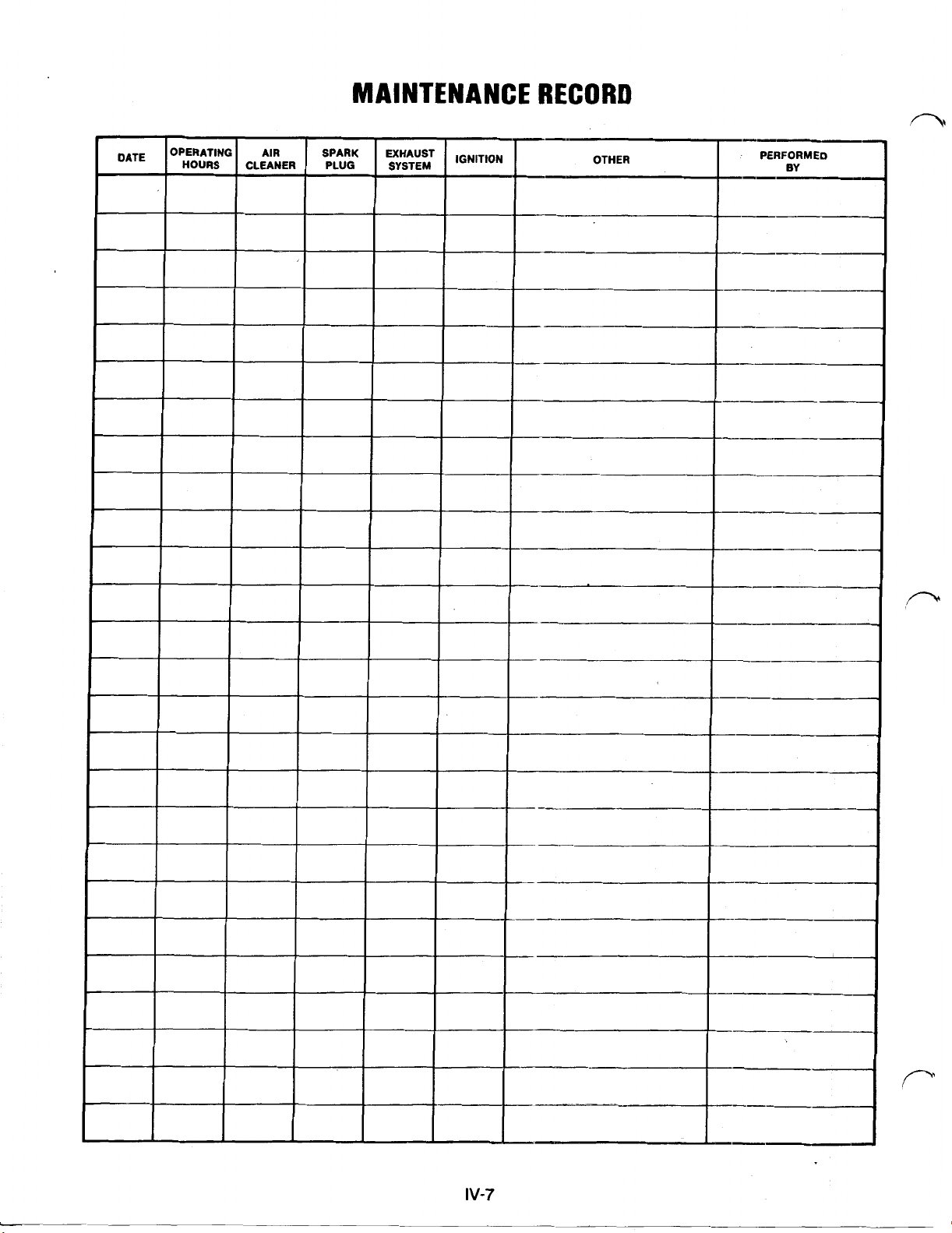
 Loading...