

Toro 144-1620 Installation Instructions

HDDriveLinkKit
144-1620
HD-Antriebsverbindungskit
144-1620
Kitbielletted'entraînementhauterésistance
144-1620
Heavy-dutyaandrijfkoppeling
144-1620
FormNo.3443-146RevA
www.T oro.com.
*3443-146*

HDDriveLinkKit
ModelNo.144-1620
Installation
LooseParts
Usethechartbelowtoverifythatallpartshavebeenshipped.
FormNo.3443-134RevA
InstallationInstructions
Description
Nopartsrequired
Tractionplate1
Traction-cablebracket1
Bolt2
Nut2
Tractionrod1
PreparingtheMachine
1.Movethemachinetolevelsurface.
2.Shutofftheengine,removethekey,andwaitfor
allmovingpartstostop.
3.Disconnectthespark-plugwire.
InstallingtheKit
InstallingtheTractionPlateand
Bracket
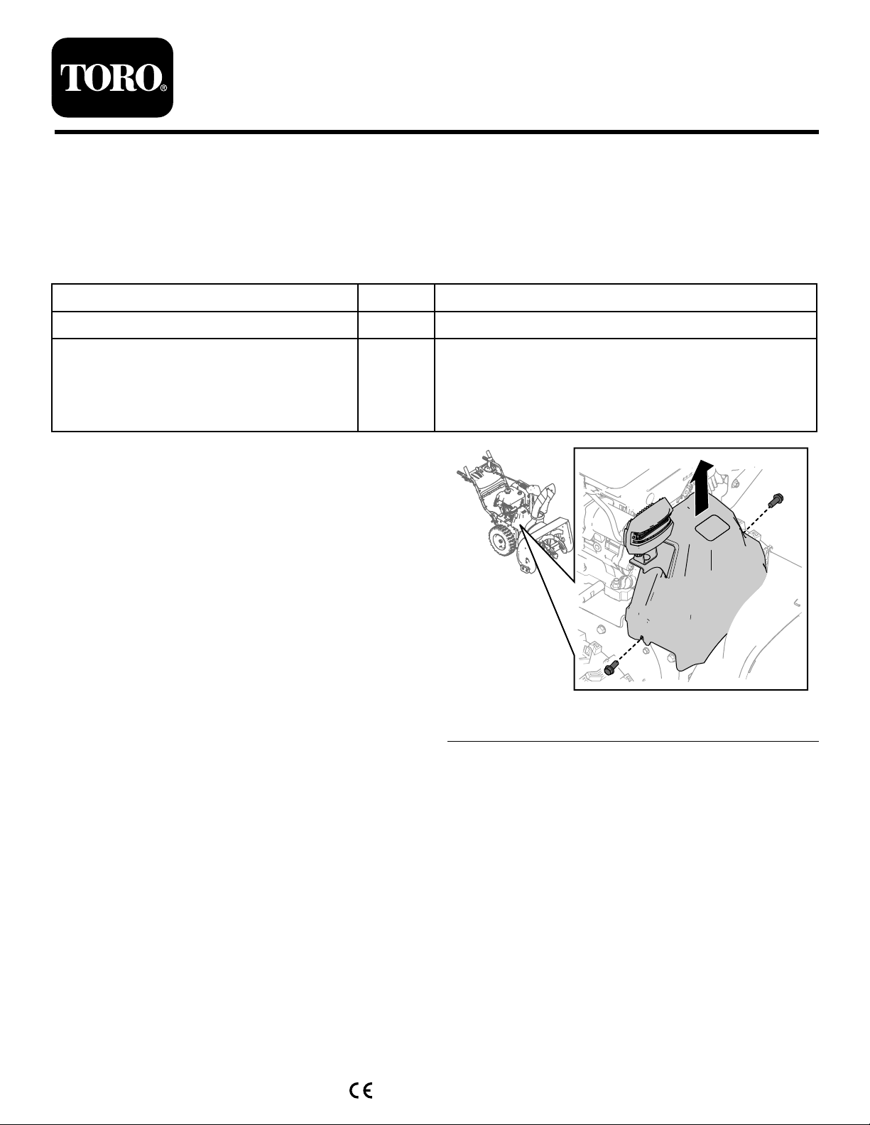
1.Removethe2screwsthatareholdingthebelt
coverinplace(Figure1).
Qty.
Use
–
Preparethemachine.
Installthekit.
g260066
Figure1
2.Removethebeltcover(Figure1).
©2020—TheT oro®Company
8111LyndaleAvenueSouth
Bloomington,MN55420
Registeratwww.T oro.com.
3.Unhookthespringfromtheexistingtraction
plate(Figure2).
OriginalInstructions(EN)
PrintedintheUSA
AllRightsReserved
*3443-134*
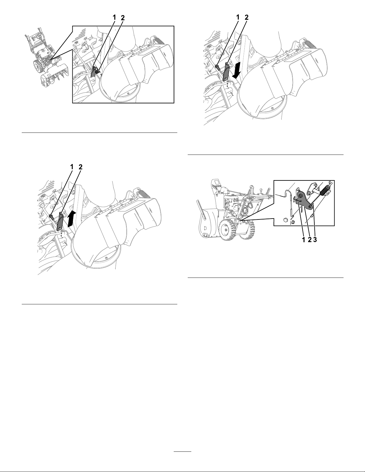
Figure2
g340063
1.Existingtractionplate
2.Spring
4.Removetheexistingtractionplatefromthe
frictionwheelplatebyremovingtheboltholding
itinplace(Figure3).
Figure3
1.Tractionplatebolt2.Existingtractionplate
g340065
Figure4
1.Tractionplatebolt2.Newtractionplate
6.Intherearofthemachine,unhookthetraction
cablefromthetraction-cablebracket(Figure5).
g340066
Figure5
1.Tractionrod3.Tractioncable
2.Traction-cablebracket
g340064
7.Unhookthetractionrodfromthetraction-cable
bracketandslidetherodoutthebackofthe
machine.
5.Installthenewtractionplateonthefrictionwheel
plateusingthepreviouslyremovedbolt(Figure
4).
8.Removetheexistingtraction-cablebracketfrom
thecrankbracketbyremovingtheboltandnut
holdingitinplace(Figure6).
2
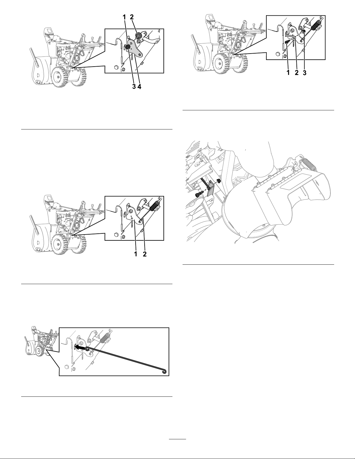
Figure6
1.Crankbracket
2.Bolt4.Existingtraction-cable
3.Nut
bracket
9.Installthenewtraction-cablebracketonthe
crankbracketusingthepreviouslyremovedbolt
andnut.
10.Hookthetractioncableonthenewtraction-cable
bracketasshowninFigure7.
Note:Ensurethatthetractioncableisoriented
asshowninFigure7.
g340092
Figure9
g340089
1.Bolt3.Nut
2.Tractionrod
3.Connecttheotherendoftherodtothenew
tractionplateusingaboltandnutincludedwith
thiskit(Figure10).
Figure7
1.Newtraction-cablebracket2.Tractioncable
InstallingtheTractionRod
1.Insertthenewtractionrodthroughtherearof
themachine(Figure8).
Figure8
2.Connecttheoneendoftherodtothenew
traction-cablebracketusingaboltandnut
includedwiththekitasshowninFigure9.
g340093
Figure10
g340090
CompletingtheInstallation
1.HookspringthewasremovedinStep3of
InstallingtheTractionPlateandBracket(page
1)onthenewtractionplate.
2.Installthebeltcoveronthemachineusingthe2
correspondingscrews.
3.Installthesparkplugwire.
4.Checktheoperationofthetractioncableand
adjustitifneeded;refertoCheckingand
AdjustingtheTractionCable(page4).
g340091
3
Maintenance
RecommendedMaintenanceSchedule(s)
MaintenanceService
Interval
Aftertherst2hours
Yearly
MaintenanceProcedure
•Aftertherst2hours—Inspectthetractioncableandadjustitifnecessary.
•Inspectthetractioncableandadjustorreplaceitifnecessary.
ControlsSystem
Maintenance
CheckingandAdjustingthe
TractionCable
ServiceInterval:Aftertherst2hours—Aftertherst
2hours—Inspectthetractioncable
andadjustitifnecessary.
Yearly—Inspectthetractioncableandadjustor
replaceitifnecessary .
Ifthemachinedoesnotdriveintheforwardorreverse
speedsoritdriveswhenyoureleasethetractionlever,
adjustthetractioncable.
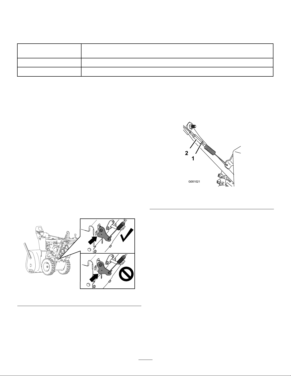
Withthetractionleverdisengaged,ensurethatthe
bottomofthetraction-cablebracketistouchingthe
frameofthemachine(Figure11).
2.Loosenortightentheturnbuckletountilthe
cableistaughtandthebottomofthebracket
touchestheframeofthemachine.
3.Tightenthejamnut(Figure12).
g001021
Figure12
1.Jamnut2.Turnbuckle
Figure11
Ifthebottomofthetraction-cablebracketisnot
touchingtheframeofthemachine,theleft(traction)
cableisnotproperlyadjusted.
Toadjustthetractioncable,dothefollowing:
1.Loosenthejamnut.
g259431
4
 Loading...