


ElectricDeckLiftKit
ZMaster
ModelNo.144-0390
®
4000SeriesRidingMower
Installation
LooseParts
Usethechartbelowtoverifythatallpartshavebeenshipped.
FormNo.3444-414RevB
InstallationInstructions
ProcedureDescription
1
2
3
4
5
6
7
8
Nopartsrequired
Nopartsrequired
Nopartsrequired
Nopartsrequired
Leftmotion-controllever
Outeractuatorbracket
Inneractuatorbracket1
Locknut(1/2inch)
Pivotpin1
Carriagebolt(5/16x2-3/4inches)
Carriagebolt(5/16x3/4inch)
Locknut(5/16inch)
Hex-headbolt(1/2x1-1/4inches)
Deckliftwireharness
Push-mountfastener
Relay2
Taptitescrew1
Nopartsrequired
Qty.
Use
–
–
–
–
1
1
2
2
2
4
1
1
1
–
Preparethemachine.
Removetheleftsidepodandfuel-tank
cap.
Removetheexistingleftmotion-control
lever.
Removethedeck-liftspring.
Installthenewleftmotion-controllever.
Installtheactuatorbracketsandrear-lift
hardware.
Routethewireharnessandinstallthe
relays.
Installtheleftsidepodandfuel-tank
cap.
9
10
11
12
©2021—TheT oro®Company
8111LyndaleAvenueSouth
Bloomington,MN55420
Nopartsrequired
Actuator1
Pinclip1
Flange-headbolt(1/2x2-1/4inches)
Locknut(1/2inch)
Nopartsrequired
Nopartsrequired
Registeratwww.T oro.com.
–
1
1
–
–
OriginalInstructions(EN)
Connectthewireharness.
Installtheactuator.
Removethetransportlock.
Checkthemowerdeckheightofcutand
rake.
PrintedintheUSA
AllRightsReserved
*3444-414*
Note:Determinetheleftandrightsidesofthemachinefromthenormaloperatingposition.
8.Supportthemowerdeckusing4x4blocksof
wood.
1
PreparingtheMachine
NoPartsRequired
Procedure
1.Parkthemachineonalevelsurface.
2.Disengagetheblade-controlswitch.
3.Movethemotion-controlleversoutwardtothe
NEUTRAL-LOCKposition.
4.Engagetheparkingbrake.
5.Shutofftheengineandremovethekey.
6.Disconnectthenegativebatterycable.
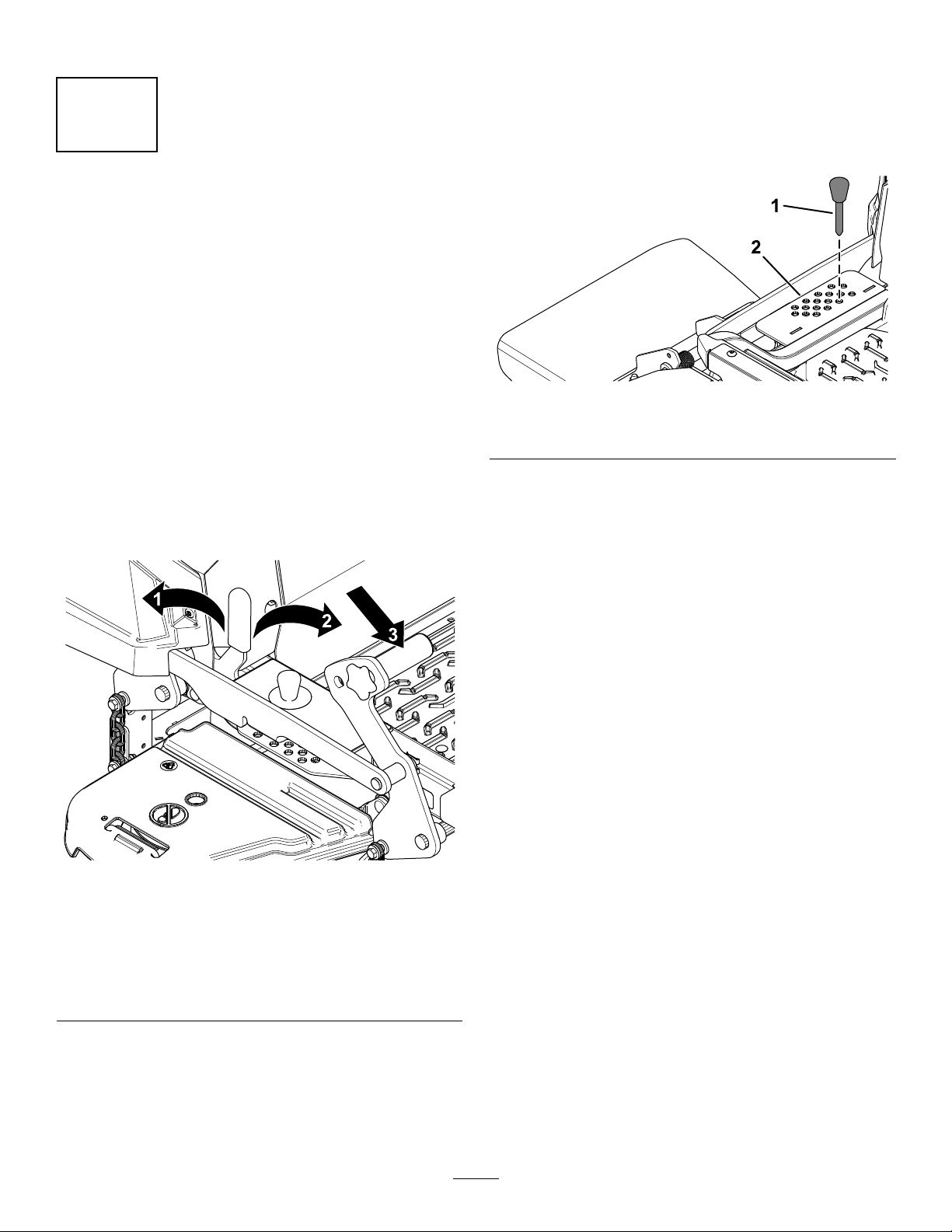
7.Pushthedeck-liftpedalfullyforwardtolockthe
mowerdeckintheTRANSPORTposition(Figure
1).
9.Removetheheight-of-cutpinfromthe
height-of-cutbracket(Figure2).
g332766
Figure2
1.Height-of-cutpin2.Height-of-cutbracket
1.LOCKposition—the
mowerdecklocksinto
thetransportposition.
2.UNLOCKposition—the
mowerdeckdoesnotlock
intothetransportposition.
g332768
Figure1
3.Pushonthedeck-liftpedal
usingyourfoottoraisethe
mowerdeck.
2
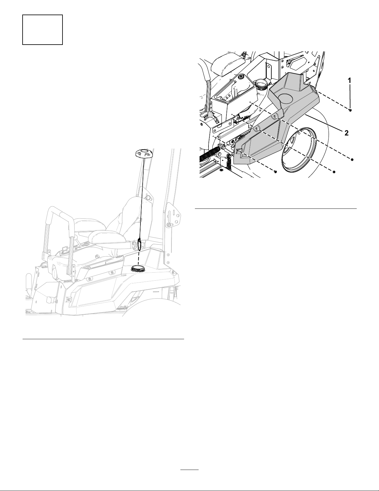
2.Removethe4shoulderscrewssecuringtheleft
sidepodandremovetheleftsidepod(Figure4).
2
RemovingtheLeftSidePod
andFuel-TankCap
NoPartsRequired
Procedure
1.Removethefuel-tankcapfromtheleftsidepod
(Figure3).
Retainthefuel-tankcapforlaterinstallation.
Retaintheleftsidepodand4shoulderscrews
forlaterinstallation.
g345968
Figure4
1.Shoulderscrew2.Leftsidepod
Figure3
3.Installthefuel-tankcap(Figure3).
g345966
3

3
4
RemovingtheExistingLeft
Motion-ControlLever
NoPartsRequired
Procedure
Removethe2ange-headbolts(3/8x1inch)securing
theexistingleftmotion-controlleverandremovethe
leftmotion-controllever(Figure5).
Retainthe2ange-headbolts(3/8x1inch)forlater
installation.
RemovingtheDeck-Lift
Spring
NoPartsRequired
Procedure
1.Removethespringboltsecuringthefrontofthe
deck-liftspring(Figure6).
2.Removetheshoulderboltandlocknut(1/2inch)
securingtherearofthedeck-liftspring(Figure
6).
3.Removethedeck-liftspring(Figure6).
Figure5
g345967
Figure6
1.Springbolt3.Locknut(1/2inch)
2.Deck-liftspring
4
4.Shoulderbolt
g346041
 Loading...