

Page 1
MuferKit
Grandstand
ModelNo.132-1547
ModelNo.132-1548
ModelNo.132-1549
Note:Determinetheleftandrightsidesofthemachinefromthenormaloperatingposition.
ThisproductcontainsachemicalorchemicalsknowntotheStateofCaliforniato
causecancer,birthdefects,orreproductiveharm.
®
Mowers
Proposition65Warning
WARNING
CALIFORNIA
FormNo.3396-687RevA
InstallationInstructions
Installation
LooseParts
Usethechartbelowtoverifythatallpartshavebeenshipped.
Description
Mufer
Rightbracket1
Leftbracket
Spacer
Bolt(5/16x1inch)
Nut(5/16inch)
Gasket
Qty.
Use
1
1
2
2
2
2
Installthekit.
©2015—TheToro®Company
8111LyndaleAvenueSouth
Bloomington,MN55420
Registeratwww.T oro.com.
OriginalInstructions(EN)
PrintedintheUSA
AllRightsReserved
*3396-687*A
Page 2
InstallingtheKit
KawasakiEngines
RemovingtheExistingBracketsand
Mufer
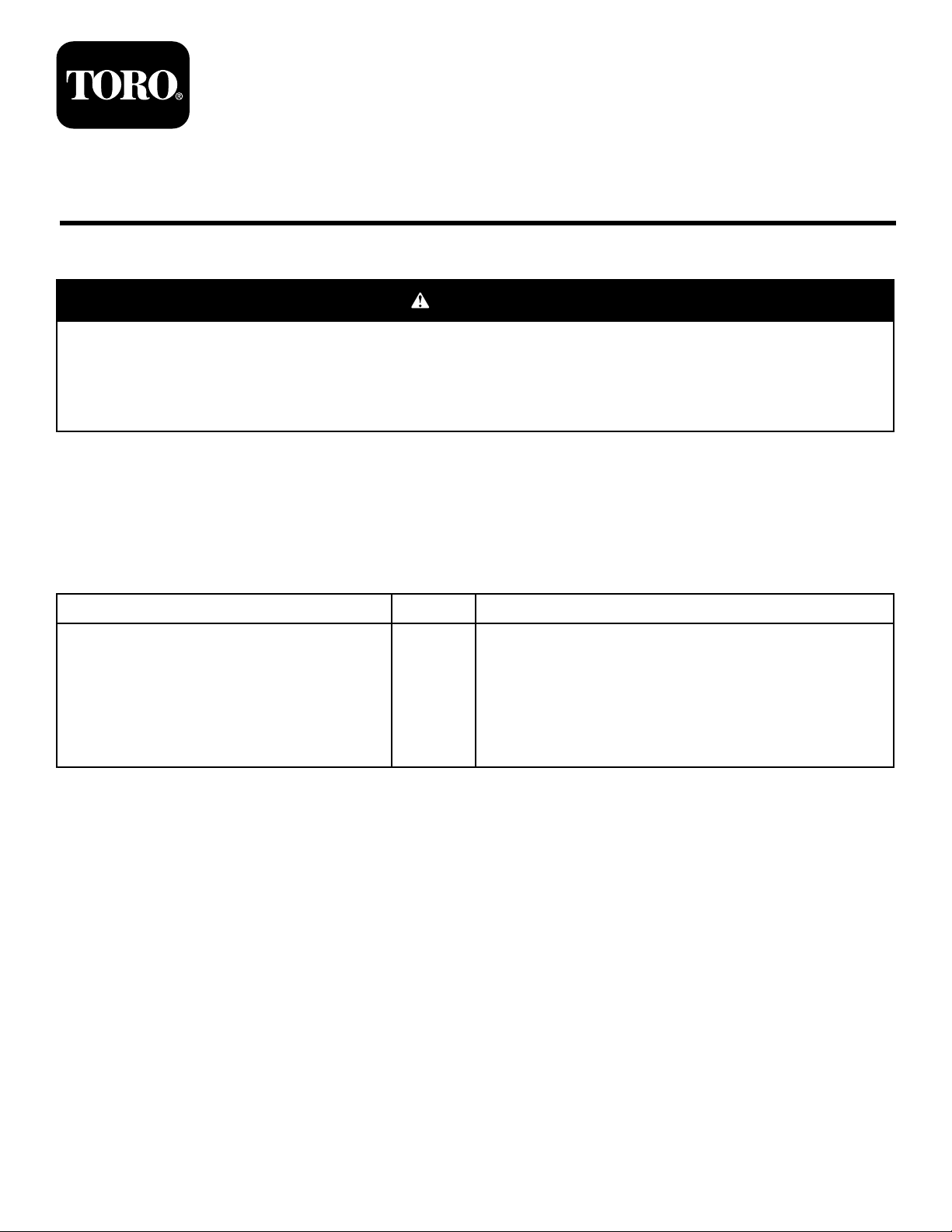
1.Removetheleftbracket(Figure1).
Note:Retainthe2lockwashersand2bolts(M8).
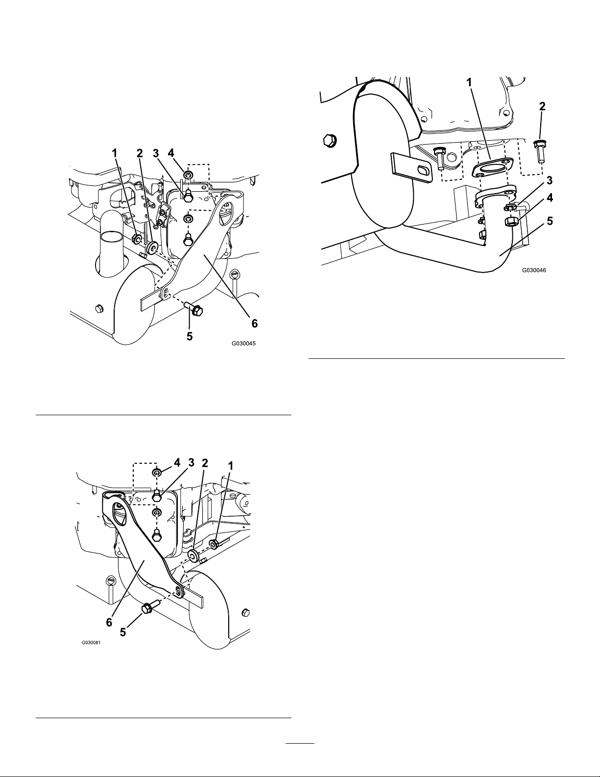
3.Removethemufer(Figure3).
Note:Retainthe4nuts(M8),4lockwashers,and4
bolts(M8).
Figure3
Leftsideofmufershown
Figure1
1.Nut4.Lockwasher
2.Spacer5.Bolt(5/16x1inch)
3.Bolt(M8)6.Leftbracket
2.Removetherightbracket(Figure2).
Note:Retainthe2lockwashersand2bolts(M8).
1.Gasket4.Nut(M8)
2.Bolt(M8)5.Mufer
3.Lockwasher
InstallingtheNewMuferandBrackets
1.Installthenewmuferand2newgasketstotheengine
usingthenuts(M8),lockwashers,andbolts(M8)that
youremovedfromthepreviousmufer(seeFigure3).
2.Installthenewrightbrackettotheengineusing2bolts
(M8)and2lockwashersthatyoupreviouslyremoved
(seeFigure2).
3.Installthenewleftbrackettotheengineusingthe
2bolts(M8)and2lockwashersthatyoupreviously
removed(seeFigure1).
4.Fastenthemufertoeachbracketusinganut(5/16
inch),spacer,andbolt(5/16x1inch)asshownin
Figure1andFigure2.
5.Torqueallfastenersto26to31N-m(19to23ft-lb).
Important:Tightenthefastenerssecuring
themufertotheenginebeforetighteningthe
fastenerssecuringthebracketstothemufer.
Figure2
1.Nut4.Lockwasher
2.Spacer5.Bolt(5/16x1inch)
3.Bolt(M8)
6.Rightbracket
2
Page 3

InstallingtheKit
KohlerEngines
RemovingtheExistingBracketsand
Mufer
1.Removetheleftbracket.
Note:Retainthe3bolts(M6).
3.Removethemufer(Figure6).
Note:Retainthe4nuts(M8)and4bolts(M8).
Figure6
Leftsideofmufershown
1.Bolt(M8)3.Nut(M8)
2.Gasket4.Mufer
Figure4
1.Nut
2.Spacer5.Bolt(5/16x1inch)
3.Bolt(M6)
4.Leftbracket
2.Removetherightbracket(Figure5).
Note:Retainthe3bolts(M6).
InstallingtheNewMuferandBrackets
1.Installthenewmuferand2newgasketstotheengine
usingthenuts(M8)andbolts(M8)thatyouremoved
fromthepreviousmufer(seeFigure6).
2.Applythread-lockingcompoundto2bolts(M6)that
youpreviouslyremovedandinstallthenewright
brackettotheengine(seeFigure5).
3.Applythread-lockingcompoundtotheother3bolts
(M6)thatyoupreviouslyremovedandinstallthenew
leftbrackettotheengine(seeFigure4).
4.Fastenthemufertoeachbracketusinganut(5/16
inch),spacer,andbolt(5/16x1inch)asshownin
Figure4andFigure5.
5.Torquethefasteners(M8)securingthemufertothe
engineto26to31N-m(19to23ft-lb).
Important:Tightenthefastenerssecuring
themufertotheenginebeforetighteningthe
fastenerssecuringthebracketstothemufer.
6.Torquethefasteners(M6)securingthebracketsto
theengineandthefasteners(5/16inch)securingthe
bracketstothemuferto6to8.7N-m(53to77in-lb).
1.Nut
2.Spacer
3.Bolt(5/16x1inch)
Figure5
4.Bolt(M6)
5.Rightbracket
3
Page 4

 Loading...