

Page 1
ZapAlertGroundStakeRelocationKit
2024and4045DirectionalDrill
ModelNo.131-9018
ModelNo.131-9019
ThisproductcontainsachemicalorchemicalsknowntotheStateofCaliforniato
causecancer,birthdefects,orreproductiveharm.
LooseParts
Usethechartbelowtoverifythatallpartshavebeenshipped.
FormNo.3396-948RevA
InstallationInstructions
WARNING
CALIFORNIA
Proposition65Warning
Description
2024DirectionalDrillbracket1
4045DirectionalDrillbracket1
Grommets
Bolts(M12)
Locknuts(M12)
Junctionblock1
Bolts(M5)
Nuts(M5)
Strikealertcable
Negativebatterycable1
Stake
Bolt(M6)
Flangenut(3/8inch)
Nopartsrequired
RelocatingtheZap-Alert
Assembly
RemovingtheExistingCableand
Bracket
Qty.
Use
2
2
2
2
2
1
1
1
1
–
Installthebrackets.
Routethecables.
Testthezap-alertsystem.
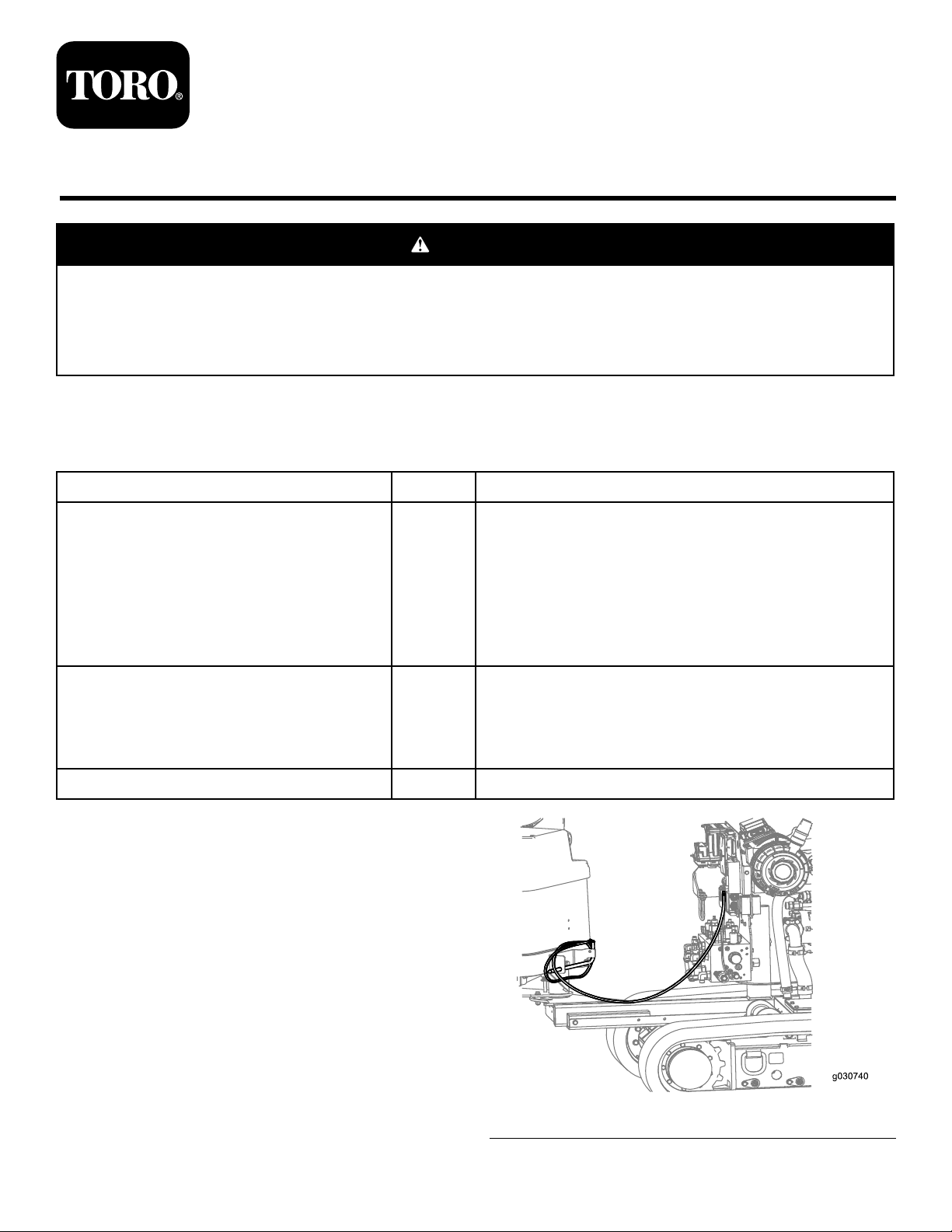
Parkthemachineonalevelsurfaceandturntheengineoff.
Removethezap-alertcableandbracket(Figure1).
©2015—TheT oro®Company
8111LyndaleAvenueSouth
Bloomington,MN55420
Registeratwww.T oro.com.
Figure1
OriginalInstructions(EN)
PrintedintheUSA.
AllRightsReserved
*3396-948*A
Page 2
InstallingtheBrackets
InstallingtheBracketsforthe4045
DirectionalDrill
InstallingtheBracketsforthe2024
DirectionalDrill
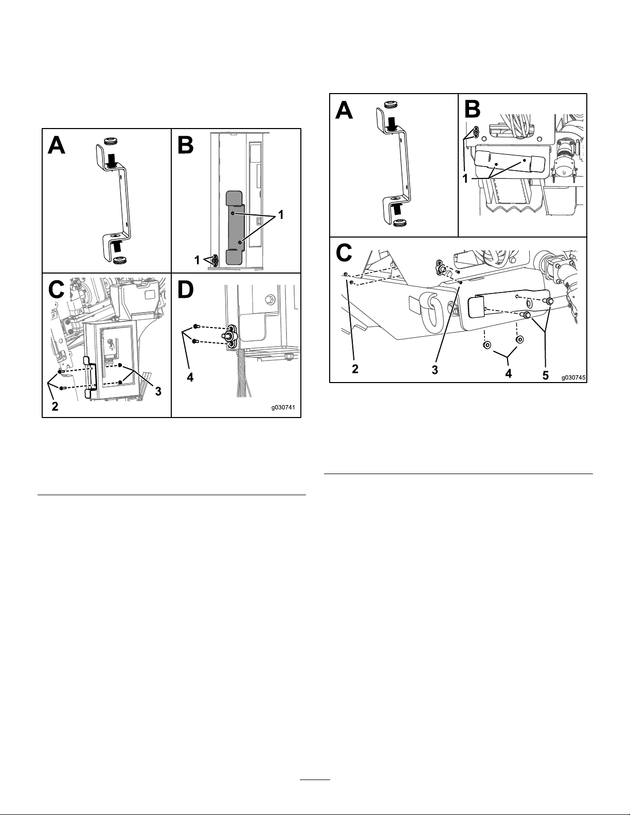
1.Installthegrommetsontothebracket(BoxAofFigure
2).
1.Installthegrommetsontothebracket(BoxAofFigure
3).
Figure2
2024DirectionalDrill
1.Drillholeshere
2.Bolts(M12)4.Bolts(M5)
2.Usingthebracketandjunctionblockasaguide,mark
anddrill4holesasshowninBoxBofFigure2.
3.Securethebracketsusing2Bolts(M12)and2locknuts
(M12)asshowninBoxCofFigure2.
4.Torquetheboltsto80to100N-m(59to73ft-lb).
5.Securethejunctionblockusing2Bolts(M5)and2nuts
(M5)asshowninBoxDofFigure2.
6.Torquetheboltsto791to971N-cm(70to86in-lb).
3.Locknuts(M12)
Figure3
4045DirectionalDrill
1.Drillholeshere
2.Nuts(M5)5.Bolts(M12)
3.Bolts(M5)
2.Usingthebracketandjunctionblockasaguide,mark
anddrill4holesasshowninBoxBofFigure3.
3.Securethebracketsusing2Bolts(M12)and2locknuts
(M12)asshowninBoxCofFigure3.
4.Torquetheboltsto80to100N-m(59to73ft-lb).
5.Securethejunctionblockusing2Bolts(M5)and2nuts
(M5)asshowninBoxDofFigure3.
6.Torquetheboltsto791to971N-cm(70to86in-lb).
4.Nuts(M12)
2
Page 3

RoutingtheCables
RoutingtheCablesforthe2024
DirectionalDrill
1.Connectthestaketothenegativebatterycableusing1
bolt(M6)asshowninFigure4.
Figure4
1.Bolt(M6)
2.Placethestakeinthebracketandwrapthe
negative-batterycablearoundthebracketasshownin
Figure5.
Figure5
2024DirectionalDrill
Figure6
2024DirectionalDrill
4.Routethestrike-alertcableasshowninBoxCandBox
DofFigure6.
5.Connectthestrike-alertcabletothemachineusing1
angenut(3/8inch)asshowninBoxBofFigure6.
3.Connectthestrike-alertcabletothejunctionblock
using1(3/8inch)angenutasshowninBoxAof
Figure6.
3
Page 4

RoutingtheCablesforthe4045
DirectionalDrill
1.Connectthestaketothenegative-batterycableusing1
bolt(M6)asshowninFigure4.
2.Placethestakeinthebracketandwrapthe
negative-batterycablearoundthebracketasshownin
Figure7.
Figure7
4045DirectionalDrill
3.Connectthestrike-alertcabletothejunctionblock
using1(3/8inch)angenutasshowninBoxAof
Figure8.
TestingtheZap-AlertSystem
Testthezap-alertsystem;refertoyourmachineOperator’ s
Manual.
Figure8
4045DirectionalDrill
4.Routethestrike-alertcableasshowninBoxBof
Figure8.
5.Connectthestrike-alertcabletothemachineusing1
angenut(3/8inch)asshowninBoxCofFigure8.
4
 Loading...