

Page 1

HydraulicSystemCoolingKit
GrandStand
ModelNo.121-7480
®
Installation
LooseParts
Usethechartbelowtoverifythatallpartshavebeenshipped.
FormNo.3373-396RevB
Mower
InstallationInstructions
ProcedureDescription
1
2
3
4
5
6
Nopartsrequired
Nopartsrequired
Hydraulicsystemcoolingassembly1
Bolt(5/16x3/4inch)
Nut(5/16inch)
61cm(24inch)hose
HoseassemblywiththeT-connector1
Cabletie
Hoseclamps
Wireharness1
Cabletie
Nopartsrequired
Qty.
10
Use
–
–
2
2
1
2
5
–
Preparingtheunit.
Removingthelowpressurehoses.
Installingthehydraulicsystemcooling
assembly.
Installingthelowpressurehoses.
Routingthewireharness.
Bleedingthehydraulicsystem.
©2012—TheT oro®Company
8111LyndaleAvenueSouth
Bloomington,MN55420
Registeratwww.T oro.com.
OriginalInstructions(EN)
PrintedintheUSA.
AllRightsReserved
*3373-396*B
Page 2
1
1
2
3
g018697
1
2 3
1
g018698
PreparingtheUnit
NoPartsRequired
Procedure
WARNING
Hydraulicuidescapingunderpressurecan
penetrateskinandcauseinjury.
Figure1
•Makesureallhydraulicuidhosesandlinesare
ingoodconditionandallhydraulicconnections
andttingsaretightbeforeapplyingpressureto
thehydraulicsystem.
•Keepyourbodyandhandsawayfrompin
holeleaksornozzlesthatejecthighpressure
hydraulicuid.
•Usecardboardorpapertondhydraulicleaks.
•Safelyrelieveallpressureinthehydraulicsystem
beforeperforminganyworkonthehydraulic
system.
•Seekimmediatemedicalattentionifuidis
injectedintoskin.
1.Positionmachineonalevelsurface.
2.Disengagethepowertakeoff(PTO)andsetthe
parkingbrake.
3.Stoptheengineandwaitforallmovingpartstostop
beforeleavingtheoperatingposition.
4.Removethekey.
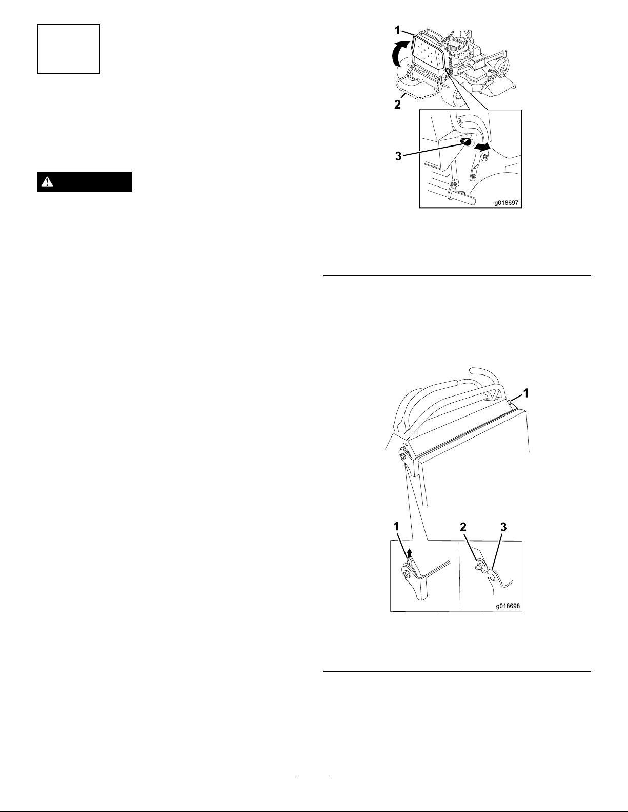
1.Platformup
2.Platformdown
9.Removethehairpincottersecuringtherearcushion
bracket(Figure2).
10.Slidethebushingnexttothemachine(Figure2).
11.Lowertherearcushionbracketontotheplatform
(Figure1andFigure2).
3.Pulltheknobouttorelease
theplatform
Figure1).
Figure33).
Figure2
1.Hairpincotter3.Rearcushionbracket
2.Bushing
5.Removethebatterycover(
6.Removethenegativebatterycablefromthebattery.
7.Lowerthemowerdecktothelowestheight-of-cut
setting.
8.Lowertheplatform(
2
Page 3
2
1
g01842 5
2
3
g018420
1
2
g018419
1
2
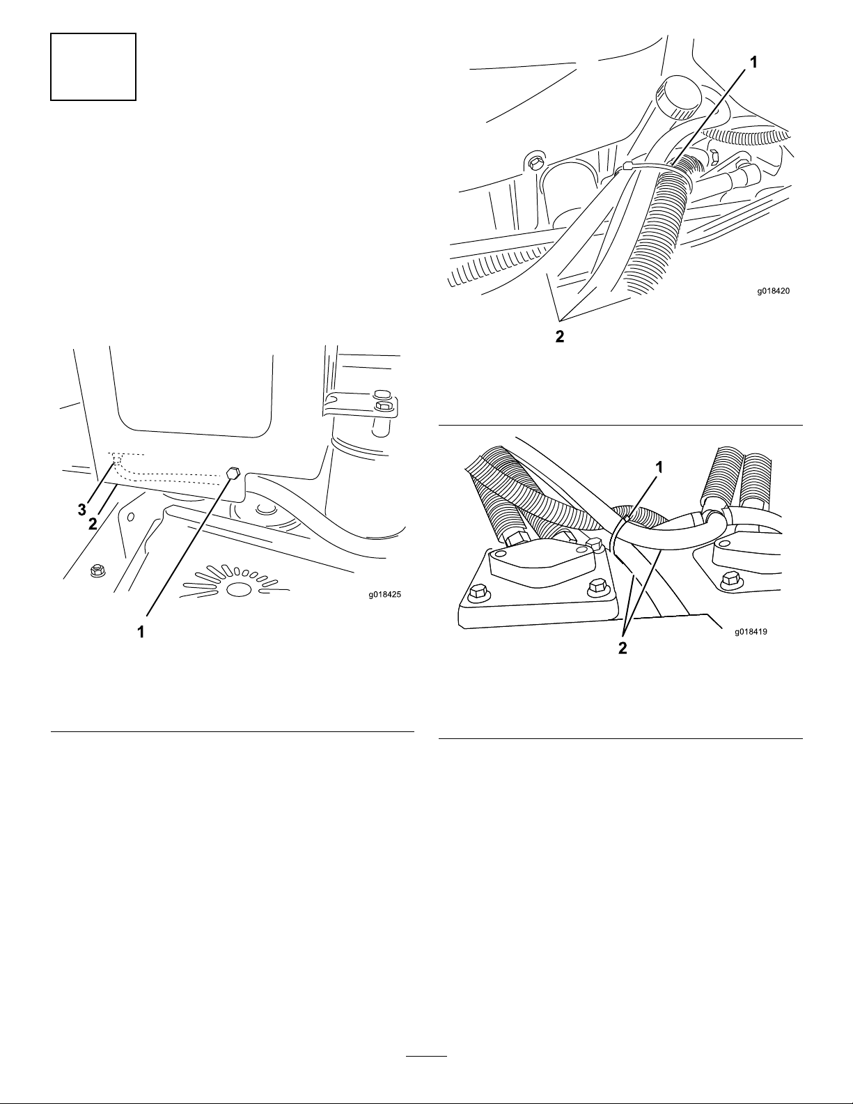
RemovingtheLowPressure
Hoses
NoPartsRequired
Procedure
1.Removethebolt,nut,andR-clampsecuringthehose
connectingtheright-handpumptothehydraulic
reservoirbracket(Figure3).
Note:DiscardtheR-clamp.
Figure4
Yourmodelmayvaryfromthisdiagram.
Figure3
1.Boltsecuringthehose3.Frontconnectoron
hydraulicreservoirtank
2.Hydraulicreservoirbracket
2.Removethelowpressurehosefromthefronttting
underthehydraulicreservoirtank(Figure3).
Note:Draintheoilintoanoilpan.
1.Cabletie
1.Cabletie
2.Hoses
Figure5
Yourmodelmayvaryfromthisdiagram.
2.Lowpressurehoses
3.Removeanddiscardthecabletiessecuringthelow
pressurehoses(
Figure4andFigure5).
3
Page 4
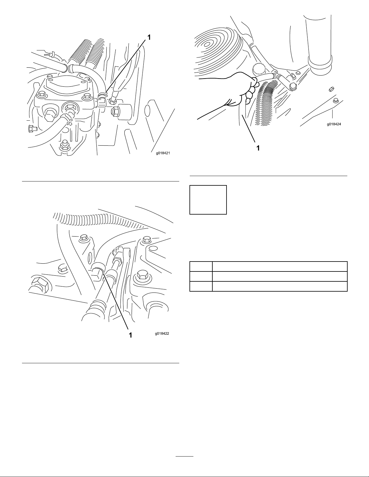
4.Removethelowpressurehosefromtheright-hand
1
g018421
1
g018422
1
g018424
pump(Figure6).
Figure6
1.Disconnecthere
5.Removethelowpressurehosefromtheleft-hand
pump(Figure7).
Figure8
1.Removehose
3
InstallingtheHydraulic SystemCoolingAssembly
Partsneededforthisprocedure:
1Hydraulicsystemcoolingassembly
2
Bolt(5/16x3/4inch)
2
Nut(5/16inch)
Procedure
1.Usinga5/16inchdrillbit,reamtheholeinthe
reservoirbracket(Figure9).
Figure7
1.Disconnecthere
6.Removethehosefromtheunit(Figure8).
4
Page 5

1
g018426
g018327
1
g018427
1
2
2
Figure11
1.Hole
2.Locatetheserialnumberdecal.
Figure10
1.Locationofthemodelandserialnumbers
Figure9
1.Uppersetoftheholesfor
2011models.
2.Lowersetofholesfor
2009and2010models.
3.Determineyourmodelyearfromtheserialnumber.
•2009—serialnumberrange290000001andup
•2010—serialnumberrange310000001andup
•2011—serialnumberrange311000001andup
4.Locatethemountingholesinthecoolingassemblythat
willberequiredforyourunit.
Note:Usetheuppersetoftheholesfor2011models.
Usethelowersetofholesfor2009and2010models.
5
Page 6

5.Alignthecoolingassemblytothereservoirbracket
g018429
1
g018428
1
1
g018451
(Figure12).
Figure12
1.Coolingassembly
6.Usingthecorrectsetofholesforyourunit,secure
therightsideofthecoolingassemblytothehydraulic
reservoirbracketusingabolt(5/16x1inch)andnut
(5/16inch)(Figure12andFigure13).
Figure14
1.Boltandnut
8.Securethecoolerassemblyusingtheboltandnut
(Figure14).
4
Figure13
1.Boltandnut
7.Usingthecoolerbracketasatemplate,drillthesecond
5/16inchholeintothereservoirbracket(Figure12,
Figure13,andFigure14).
InstallingtheLowPressure Hoses
Partsneededforthisprocedure:
1
61cm(24inch)hose
1HoseassemblywiththeT-connector
2
Cabletie
5
Hoseclamps
Procedure
Note:Thehosefromtheleft-handpumpconnectstothe
radiatorinletport(Figure15).
6
Page 7

1
2
3
g018473
1.Coolingassemblyinlet
g018472
1
2
3
4
5
6
7
g018452
1
2
1
g018690
2
3
4
5
port
2.Hosefromleft-handpump
connectingtocooling
assemblyinletport
Figure15
3.Left-handpump
Note:Securethehosewithahoseclampsothatthe
tabsoftheclamparepointingdownwardasshown.
Figure17
1.Left-handpump
2.Returnport
2.Routethehoseandinstalltheotherendtothecooling
assemblyinlet.
Note:Thehosefromtheright-handpumpconnectstoa
T-connector.TheshorthosecomingofftheT-connector
goestotheradiatorexitport.Theotherhoseconnectsto
thehydraulicreservoirtank
1.Hydraulicreservoirtank5.Right-handpump
2.Coolingassembly
3.Shorthose
4.Hosefromtheright-hand
pumpconnectingtothe
T-connector
Figure16
6.T-connector
7.Hoseconnectingtothe
hydraulicreservoir
Note:Rotatetabsonhoseclampasshownin
Figure18.
Figure18
1.CoolingAssemblyoutlet
2.CoolingAssemblyInlet
3.Hosecomingfromthe
left-handpump
4.Hosegoingtothe
T-connector
5.Tabsonclamp
1.Installthe61cm(24inch)hosetoleft-handpump
(Figure17.
3.InstallthehoseconnectingtheT-connectortothe
coolingassemblyoutlet(Figure16andFigure19).
7
Page 8

Note:Rotatetabsonhoseclampasshownin
1
g018454
2
g018455
1
2
g018456
1
g018457
1
Figure18.
Figure19
1.Hosegoingtothe
hydraulicreservoirtank
2.T-connector
4.InstallthehoseconnectingtheT-connectortothe
right-handpump(Figure16andFigure20).
Note:Rotatethetabsofthehoseclampsotheyare
pointingdownward.
Figure21
1.Cabletie
Figure22
Figure20
1.Right-handpump2.Hoseclamp
1.Cabletie
6.Movethedeckfromthehighestheightofcuttothe
lowestheightofcut.
5.Securethehosesusing2cableties(Figure21and
•Repeatthisstepwhileobservingthehoses.
Figure22).
•Verifythatthehosesdonotcontacthotsurfaces,
sharpedges,ormovingcontrolslinkage.
•Adjustthecabletiesandhoseroutingifneededto
avoidcontactforallheightofcutpositions.
8
Page 9

5
g018478
1
2
3
4
g018458
1
1
g018459
RoutingtheWireHarness
Partsneededforthisprocedure:
1Wireharness
10
Cabletie
Procedure
1.Beforestartingthisprocedure,observehowyouwill
routethewireharness.
Figure24
1.Coolingassemblyconnector
3.Routethecoolingassemblywireharnessunderneath
allthehosesandthroughthepumpcompartment
(
Figure25).
Figure23
1.Routingthewireharness
tothebattery
2.Relay4.Wireharnesstothe
2.Connectthecoolingassemblyconnectortothewire
harness(Figure24).
3.Relaysocket
coolingassembly
Figure25
1.Coolingassemblywireharness
4.Continueroutingthecoolingassemblywireharness
betweenthebrakerodandframe(Figure26).
9
Page 10

1
g018460
Figure26
1
2
g018475
1
g018461
1
g018691
2
1.Coolingassemblywireharness
5.Removetherelayfromthewireharnessrelaysocket
(ifinstalled).
7.Installtherelayintotherelaysocket.
8.Removeanddiscardtheprotectivecapfromtheend
oftheAUXconnectoronthewireharnessnearthe
fusebox.
9.Connectthecoolingassemblywireharnesstothe
wireharnessAUXconnectorlocatedatthefuseblock
(Figure28).
6.Installtherelaysockettotheframecrossbrace.
•For2011modelssecuretherelaysockettothe
crossbraceusinganutandbolt(Figure27).
•For2009and2010modelssecuretherelaysocket
tothecrossbraceand/orwireharness,usinga
cabletie.
Note:Thereisnoholeinthecrossbraceon2009
and2010modelsforsecuringtherelaysocketto
thecrossbrace.
Figure28
1.Wireharnesses
10.Securethewireharnesstothehosegoingtothe
coolingassemblyinletwithacabletie(
Figure29).
Figure27
2011modelshown
1.Relaysocket2.Nut
Figure29
1.Cabletie
2.Wireharness
11.Securetheclipattachedtothewireharnesstothe
frame(Figure30).
10
Page 11

1
g018689
Figure30
1
g018463
g018464
1
g018477
3
1.Attachthecliponthewireharnesstotheframe
Figure32
1.Cabletie
12.Securethecoolingassemblywireharnesstothe
R-clamplocatedinthelowerleftfrontcornerofthe
controltower,usingacabletie(Figure31).
Figure31
1.Cabletie
13.Removetheslackfromthewireharnesswhereitpasses
throughthepumpcompartment.
14.Securethecoolingassemblywireharnesstothemain
wireharnessusingacabletie(Figure32).
15.Routetheotherendofthewireharnesstothebattery
(Figure23)and(Figure33).
Figure33
1.Wingnut4.Positivebattery
connection
2.Batterycover5.Battery
3.Wireharnesstothe
positivebatteryterminal
16.Opentheredcapcoveringthepositivebatteryterminal.
17.Installtheconnectoronthecoolingassemblywire
harnesstothepositivebatteryterminal(Figure33).
18.Installtheredcap.
19.Installthenegativebatterycabletothebattery.
11
Page 12

20.Securethepathofthecoolingassemblywireharness
1
g018465
G012005
4 1 3
2
usingthecableties.
21.Installthebatterycover.
22.Installthe15ampfuseintothefuseblock(Figure34).
Figure34
1.Fuse
23.TurnthekeytotheRunpositionandverifytheelectric
fanisrunning,thenturnthekeytothestopposition.
24.Installtherearcushionbracket(Figure2).
Figure35
1.Cap3.Colduidlevel-full
2.Bafe4.Hotuidlevel-full
2.Removecapfromllerneck.(Figure35).
3.Adduidtothereservoiruntilitreachesthecoldlevel
ofthebafe(Figure35).
4.Raisetherearofthemachineupontojackstandshigh
enoughtoraisethedrivewheelsofftheground.
5.Disengagetheparkingbrake.
6.Starttheengineandmovethethrottlecontroltoidle
position.
Note:Ifthedrivewheeldoesnotrotate,itispossible
toassistthepurgingofthesystembycarefullyrotating
thetireintheforwarddirection.
6
BleedingtheHydraulicSystem
NoPartsRequired
Procedure
Note:HydraulicOilType:Toro®HYPR-OIL™500
hydraulicoilorMobil®115W -50syntheticmotoroil.
1.Cleanareaaroundcapandllerneckofhydraulictank
(Figure35).
7.Checkthehydraulicuidlevelasitdropsadduidas
requiredtomaintaintheproperlevel.
8.Repeatthisprocedurefortheoppositewheel.
9.Installthecaponthellerneck.
10.Thoroughlycleantheareaaroundeachofthecharge
pumphousings.
11.Checkthecoolingsystemconnectionsforanyleaks.
12
 Loading...