

Page 1
FormNo.3372-308RevA
48,54,and60InchBaggerFinishingKit
TITANZX/MXSeriesRidingMower
ModelNo.121-5662
ModelNo.121-5663
ModelNo.121-5664
InstallationInstructions
ThiskitrequirestheBaggerKit79328to
completeinstallation.ContactyourAuthorized
ServiceDealerorToroCustomerService
toobtainthenecessaryparts.Formore
information,visitusatwww.Toro.com.
Safety
Important:TheROPSrollbarisanintegralandeffectivesafetydevice.Keeptherollbarinthefullyraisedand
lockedpositionwhenoperatingthemower.Lowertherollbartemporarilyonlywhenabsolutelynecessary.
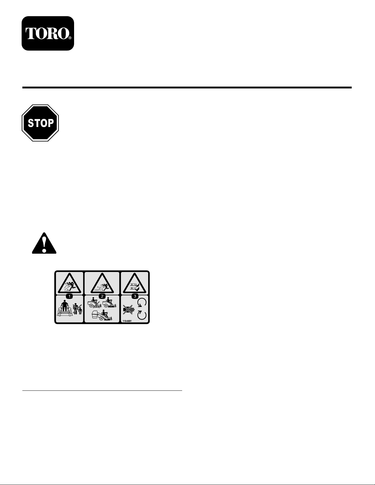
SafetyandInstructionalDecals
Safetydecalsandinstructionsareeasilyvisibletotheoperatorandarelocatednearanyareaofpotential
danger.Replaceanydecalthatisdamagedorlost.
110-6691
1.Thrownobjecthazard—keepbystandersasafedistance
fromthemachine.
2.Thrownobjecthazard,mower—donotoperatewithoutthe
deector,dischargecover,orgrasscollectionsystemin
place.
3.Cutting/dismembermentofhandorfoot—stayawayfrom
movingparts.
©2012—TheToro®Company
8111LyndaleAvenueSouth
Bloomington,MN55420
Registeratwww.T oro.com.
OriginalInstructions(EN)
PrintedintheUSA.
AllRightsReserved
Page 2

Installation
LooseParts
Usethechartbelowtoverifythatallpartshavebeenshipped.
ProcedureDescription
1
2
3
4
Weight2
Adhesivebumper2
Rod1
Washer4
Hairpin2
Spacer
Straightbafe(48inchmowerdecks
only)
Curvedbafe(54inchmowerdecks
only)
Locknut(5/16inch)
Handknob1
Washer1
Chute
Curvedbafe
Locknut(5/16inch)
Handknob1
Washer1
Chute
Circularcotterpin
Qty.
Installtheweight(Machineswithouta
ROPS).
8
1
1
1
1
1
1
1
1Installthebaggertop.
Installthechutefor48and54inch
mowerdecks.
Installthechutefor60inchmower
decks(Modelyear2010andnewer).
Use
5
6
1
InstallingtheWeight
Partsneededforthisprocedure:
2Weight
2Adhesivebumper
1Rod
4Washer
2Hairpin
8
Spacer
Procedure
Nopartsrequired
Hi-Liftblade
NumberofWeightstoUse
SizeofMowerDeck
48inch2weights1weightand
54inch2weights1weightand
60inch1weightand
1.Determinethenumberofweightsneededforyour
2.ForallMXTitanmachinesandallmachineswith60
–
3Installtheblades.
machine.
inchmowerdecks,removethe2nutsandboltsthat
securethefrontofthemowerhousingpan(Figure1).
Note:Savethenutsandboltstosecurethefrontof
themowerhousingpanlater.
Connectwiththedischargetube.
Machinewitha
ROPS
spacers
Machinewithouta
ROPS
spacers
spacers
Noweightused
Usethefollowingtabletodeterminethenumberofweights
neededforyourmachine.Forcertainmachines,notall
weightsincludedwiththekitwillbeused.
2
Page 3
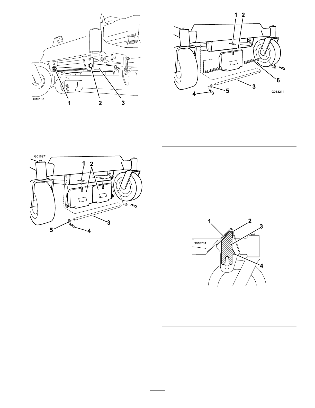
Figure1
G016271
1
2
3
4
5
G01821 1
3
5
4
1
2
6
G010701
1
2
3
4
Figure3
Installationof1weight
1.Nut3.Mowerhousingpan
2.Bolt
3.Installanadhesivebumpertotheweight(Figure2and
Figure3).
Figure2
Installationof2weights
1.Adhesivebumper4.Hairpin
2.Frontweight5.Washer
3.Rod
1.Adhesivebumper4.Hairpin
2.Frontweight5.Washer
3.Rod
6.Spacers(usedforone
weightonly)
4.Installtheweighttothefrontofthemachineframe.
5.Securetheweightwitharod,fourwashers,andtwo
hairpinsasshownin
Figure2.Usethe8spacersif
installingjustonefrontweightasshowninFigure3.
Note:Wheninstallingthefrontweightallowittorest
onthefrontlipoftheundersideofthemachineframe
asshownFigure4.Thiswillsuspendtheweightwhile
yousecureittothemachine.Usecarenottodislodge
theweightwheninstallingthesupportingrod.
Figure4
1.Cutawayofthefrontofthe
machineframe
2.Bumper4.Resttheweighthere
3.Weight
duringinstall
6.ForallMXTitanmachinesandallmachineswith
60inchmowerdecks,installthefrontofthemower
housingpanusingthenutsandboltspreviously
removed(Figure1).
Important:Wheneveryouremovethebagger
attachment,remembertoremovethefrontweightto
returntheproperstabilitytothemachine.
3
Page 4
2
G010637
1
2
2
3
4
5
6
7
InstallingtheChutefor48and 54inchMowerDecks
Partsneededforthisprocedure:
1
Straightbafe(48inchmowerdecksonly)
1
Curvedbafe(54inchmowerdecksonly)
1
Locknut(5/16inch)
1Handknob
1Washer
1
Chute
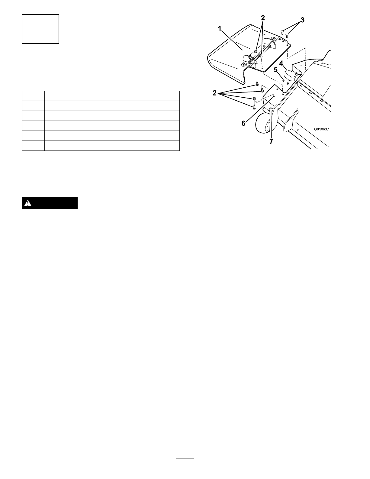
Figure5
Procedure
UsethisprocedurewheninstallingtheFinishingKiton
machineswith48and54inchmowerdecks.
WARNING
Anuncovereddischargeopeningcouldallowthe
lawnmowertothrowobjectsintheoperatoror
bystander'sdirectionandresultinseriousinjury.
Also,contactwiththebladecouldoccur.
Neveroperatethelawnmowerunlessyouinstall
acoverplate,amulchplate,oragrasschuteand
catcher.
Neveroperatethemowerwiththedischargeopening
uncovered.Adischargecover,mulchcoverorbaggingchute
mustalwaysbeusedwhenthemowerdeckisoperated.
1.Removefastenerssecuringthedeectorassemblyand
existingcutoffbafetothemowerdeck(Figure5).
Retainallfasteners.
1.Deectorassembly5.Locknut(existing)
2.Fasteners(existing),retain
3.Carriagebolt(existing)
4.Cutoffbafe(existing)
2.For54inchmowerdecksonly,removethefasteners
pluggingtheforwardhole.
3.Removethedeectorassemblyandreinstallthe
cutoffbafe.Retainallpartstoconvertthedeckto
sidedischarge.
4.Installabafetothemowerdeck(
48inchdecks,useastraightbafe.For54inch
decks,useacurvedbafe.Aligntheverticalpost
onthebafeinsidethemowerdeck.Rotatethebafe
untilthehorizontalpostalignswiththeholeinthe
frontwallofthemowerdeck.Secureittothefront
wallofthemowerdeckusingalocknut.
6.Forwardhole
7.Frontretainingclasp
Figure6).For
4
Page 5

1
2
3
4
5
6
7
G015685
Figure6
G010638
1
2
3
4
5
6
1.Retainingclasp5.Horizontalpost
2.Forwardhole6.Locknut
3.Bafe(curvedshown)
4.Verticalpost
7.Frontwallhole
Figure8
1.Flexiblelatchandretainingclasp
3
InstallingtheChutefor60
inchMowerDecks(ModelYear
5.Installthechutetothemowerdeckmakingsurethe
openingintopofthechutealignswiththeexposed
postonthemowerdecktop(Figure7).
Figure7
2010andNewer)
Partsneededforthisprocedure:
1
Curvedbafe
1
Locknut(5/16inch)
1Handknob
1Washer
1
Chute
Procedure
UsethisprocedurewheninstallingtheFinishingKiton
machineswith60inchmowerdecks(Modelyear2010and
newer).
WARNING
Anuncovereddischargeopeningcouldallowthe
lawnmowertothrowobjectsintheoperatoror
bystander'sdirectionandresultinseriousinjury.
Also,contactwiththebladecouldoccur.
1.Dischargechute
2.Handknob
3.Washer
6.Installawasherandhandknoboverthepostcoming
7.Hookthefrontexiblelatchonthechutetothe
throughthechutetop.Handtightentosecurethe
chutetothemowerdeck.
retainingclaspweldedtothefrontwallofthemower
deck(
Figure8).Hooktheexiblelatchonthebackof
thechutetotheretainingclaspweldedtotherearwall
ofthemowerdeck.
4.Postincurvedbafe
5.Frontexiblelatch
6.Openinginthetopofthe
chute
Neveroperatethelawnmowerunlessyouinstall
acoverplate,amulchplate,oragrasschuteand
catcher.
Neveroperatethemowerwiththedischargeopening
uncovered.Alwaysuseadischargecover,mulchcover,or
baggingchutewhenoperatingthemowerdeck.
1.Removefastenersthatsecurethedeectorassemblyto
themowerdeck(Figure9).
Note:Retainallfasteners.
5
Page 6

G013095
1
2
3
4
5
Figure9
G013096
1
2
3
4
5
6
7
8
9
10
G013097
1
2
3
4
5
6
4.Installthecurvedbafetothemowerdeck(Figure10).
A.Aligntheverticalpostinthecurvedbafewith
center,forwardholeinthemowerdeckandthe
horizontalpostwiththeholeinthefrontwallof
themowerdeck.
B.Securehorizontalposttothefrontwallofthe
mowerdeckusingalocknut.
5.Installthechutetothemowerdeck.
Note:Ensurethattheopeningintopofthechute
alignswiththeexposedpostonthemowerdecktop
andtheforwardverticalplatemateswiththefolded
metalbracketofthechute(Figure11).
1.Deectorassembly4.Carriagebolt(existing;
2.Locknut(existing;retain)5.Carriagebolt(existing;
3.Locknut(existing,reuse)
reuse)
retain)
2.Removethedeectorassembly.
Note:Retainallpartstoconvertthemowerdeckto
sidedischarge.
3.Locateandinstalltheangledcutoffbafetothemower
deckattherearholesinthemowerdeck(
Figure10).
Note:Usetheexistingfastenersfromthatlocationto
securetheangledcutoffbafetothemowerdeck.
Figure11
1.Dischargechute4.Foldedmetalbracket,
chute
2.Handknob5.Forwardverticalplate,
deck
3.Washer6.Exposedpostinthemower
deck,curvedbafe
1.Holeinfrontwallofthe
mowerdeck
2.Locknut
3.Horizontalpost,curved
bafe
4.Verticalpost,curvedbafe9.Locknut(existing;reuse)
5.Curvedbafe10.Center,forwardholein
Figure10
6.Highliftblade
7.Carriagebolt(existing;
reuse)
8.Angledcutoffbafe
mowerdeck
6.Installawasherandhandknoboverthepostcoming
throughthechutetop(Figure11).
7.Handtightentheknobtosecurethechutetothe
mowerdeck.
8.Hooktheexiblelatchonthechutetotheretaining
claspweldedtothesidewallofthemowerdeck
(
Figure12).
6
Page 7

G013098
1
2
Figure12
G016265
1.Retainingclasp2.Flexiblelatch
4
InstallingtheBaggerTop
Partsneededforthisprocedure:
1
Circularcotterpin
Procedure
1.Installthebaggertoptothebaggerframe.Slidethe
bracketsoverthepostsinthebaggerframeandinstall
thecircularcotterintotheholeintherighthand
post(Figure13).Rotatethebaggertopdowntothe
operatingposition.Thebaggertopiseasiertoinstallif
twopeopleworktogether.
Note:Toremovethecircularcotter,continuetorotate
itinthesamedirectionasinstalled.
1.Baggertop
2.Baggerframe
3.Bracket,baggertop
Figure13
4.Circularcotterpin
5.Post
7
Page 8

2.Liftthebaggertopandinstallthebagsbysliding
G005672
1
2
3
4
G005757
G010641
1
2
3
4
5
thebagframehooksontotheretainingbrackets
(Figure14).
5
ConnectingwiththeDischarge Tube
NoPartsRequired
Procedure
1.Slidethecurvedendofthedischargetubeintothe
openinginthebaggertop(Figure16).
Figure14
1.Bag3.Retainingbracket
2.Baggerframe4.Bagframehook
3.Lowerthebaggertopontothebag(Figure15).
1.Dischargetube,curved
end
2.Openinginbaggertop
3.Dischargetube,aredend
2.Slidethearedendofthedischargetubeoverthe
endofthechute.Movetherubberretainingstrapon
thechutesnapsoverthepegonthedischargetubeto
secureit(Figure16).
Figure15
Figure16
4.Peg
5.Rubberstrap
8
Page 9

Maintenance
6
InstallingtheBlades
Partsneededforthisprocedure:
3
Hi-Liftblade
Procedure
1.Removetheexistingmowerbladesinstalledonyour
mowerdeck.RefertotheRemovingtheBladessection
intheOperator'sManualformoreinformation.
2.InstalltheHi-Liftmowerbladeslocatedinloose
parts.RefertotheInstallingtheBladessectioninthe
Operator'sManualformoreinformation.
RemovingtheFinishingKit
Wheneverthebaggerkitisremoved,thenishingkitshould
beremovedusingthefollowingprocedure.Retainallparts
forfutureinstallation.
CAUTION
Removingthebaggerchangestheweight
distributionofthemachine.Operatingthemachine
withthefrontweightsinstalledwithoutthebagger
maycauseanunstableconditionwhichcouldresult
inalossofcontrol.
Ensurethefrontweightsareproperlyremoved
beforeoperatingthemachinewithoutthebagger
attachment.
1.Removethefrontweights.Removethefastener
securingtheweighttothemachine.Takecareto
controltheweightasthesupportrodisremoved.
2.Removethedischargetubefromthemachine.
3.Installthecutoffbafe(Figure17).
Replacethepreviouslyremovedcutoffbafefor60
inchmowerdecks(Figure10).
4.Installthedeectorassembly(Figure17andFigure18).
5.For54inchmowerdecksonly ,replacethenutandbolt
intheforwardhole(Figure17).
WARNING
Anuncovereddischargeopeningcouldallow
thelawnmowertothrowobjectsinthe
operatororbystander'sdirectionandresult
inseriousinjury.Also,contactwiththeblade
couldoccur.
Neveroperatethelawnmowerunlessyou
installacoverplate,amulchplate,oragrass
chuteandcatcher.
9
Page 10

G010637
1
2
2
3
4
5
6
7
Figure17
G013095
1
2
3
4
5
48and52inchMowerDeck
1.Deectorassembly5.Locknut(existing),reuse
2.Fasteners(existing),retain
3.Carriagebolt(existing),
reuse
4.Cutoffbafe(existing)
6.Forwardhole
7.Frontretainingclasp
BladessectionintheOperator'sManualformore
information.
•Installthestandardmowerbladesremoved
previously.RefertotheInstallingtheBlades
sectionintheOperator'sManualformore
information.
Important:TheROPSrollbarisanintegraland
effectivesafetydevice.Keeptherollbarinthefully
raisedandlockedpositionwhenoperatingthemower.
Lowertherollbartemporarilyonlywhenabsolutely
necessary.
Figure18
60inchMowerDeck
1.Deectorassembly4.Carriagebolt(existing;
2.Locknut(existing;retain)5.Carriagebolt(existing;
3.Locknut(existing,reuse)
6.Replacethemowerblades.
reuse)
retain)
•RemovetheHi-Liftmowerbladesinstalledon
yourmowerdeck.RefertotheRemovingthe
10
Page 11

Notes:
11
Page 12

 Loading...