

FormNo.3373-265RevB
g018378
1
2
DeluxeSeatKit
ZMaster
ModelNo.121-4812
Note:Formachineswith48inchmowerdecks,theweightkitmustbeinstalledtothemachineforperformanceandsafety
afterthedeluxeseatkitisinstalled.Obtainthecorrectweightkit(No.121–7576)fromanAuthorizedServiceDealer.
®
2000SeriesRidingMower
InstallationInstructions
Installation
LooseParts
Usethechartbelowtoverifythatallpartshavebeenshipped.
ProcedureDescription
1
2
3
Nopartsrequired
Deluxesuspensionseat1
Seatplate
Fancoverplate2
Flangenut(5/16inch)
Carriagebolt(5/16x3/4inch)
Decal1Installthedecal.
1
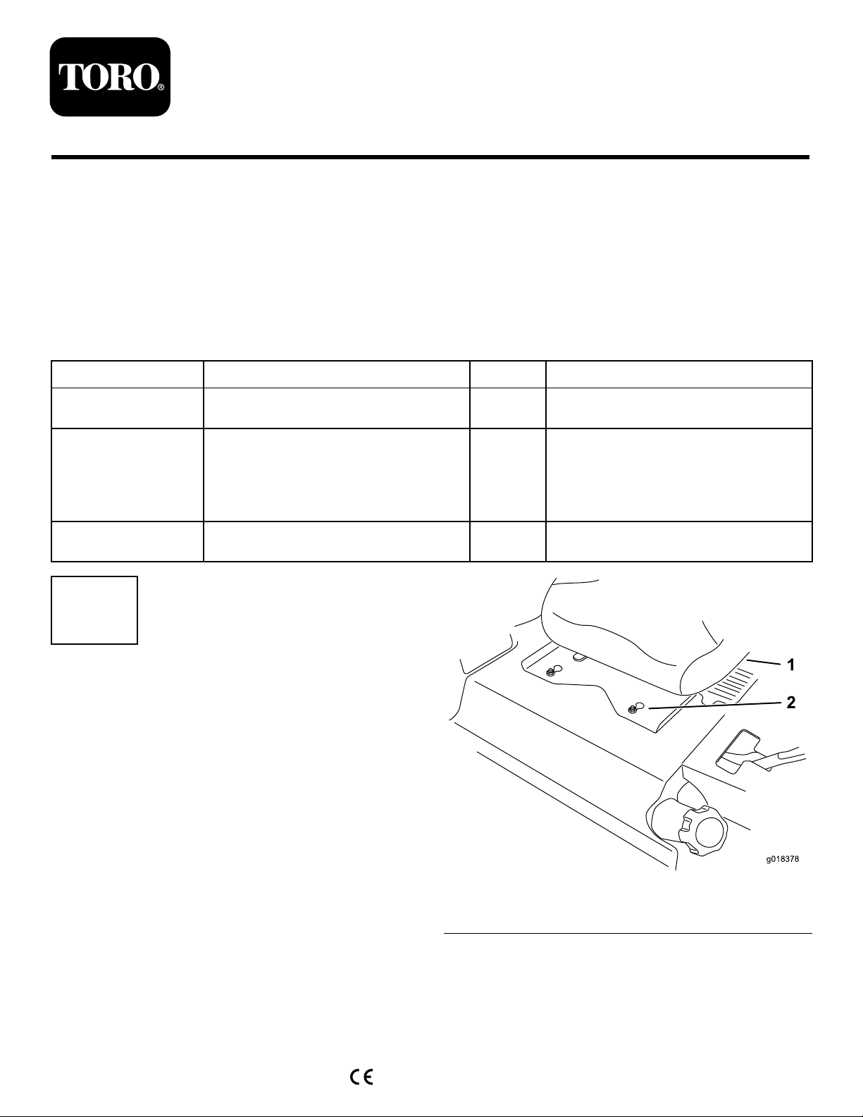
RemovingtheSeat
NoPartsRequired
Procedure
1.Movetheseatthefurthestrearpositiontoexposethe
frontnuts.
Qty.
Use
–
1
8
4
Removetheseat.
Installtheseat.
2.Loosenthefrontnuts.Thenutsdonotneedtobe
removed.
3.Movetheseattothefurthestforwardpositionto
exposetherearnuts.
4.Loosentherearnuts.Thenutsdonotneedtobe
removed.
5.Slidetheseatandseatplateforwardtoallowthefront
nutstogothroughthekeyhole(
6.Removetheseatandbasefromthemachine.
7.Unplugtheharnessconnectorfromtheseatswitch
locatedundertheseat.
©2012—TheToro®Company
8111LyndaleAvenueSouth
Bloomington,MN55420
Figure1).
Registeratwww.T oro.com.
Figure1
1.Existingseat2.Frontnutswithkeyhole
OriginalInstructions(EN)
PrintedintheUSA.
AllRightsReserved
*3373-265*B
2
g018379
1
2
3
4
5
6
5
7
8
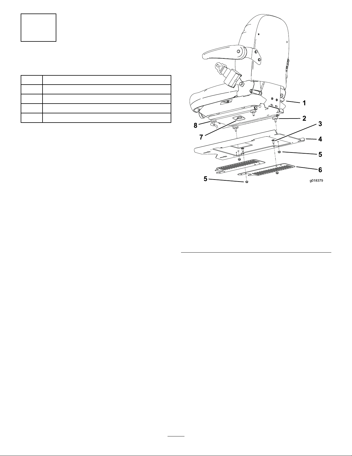
InstallingtheSeat
Partsneededforthisprocedure:
1Deluxesuspensionseat
1
Seatplate
2Fancoverplate
8
Flangenut(5/16inch)
4
Carriagebolt(5/16x3/4inch)
Procedure
1.Removetheplasticpackingcoversguardingtheseat
studs.
Note:Donotremovethespacersontheseatstuds.
2.Securetheseatplatetotheseatwith4angenuts
(5/16inch)(Figure2).
Torquethenutsto22.5ft-lb(30.5N-m).
3.Installthefancoverplatestotheseatplatewith4
carriagebolts(5/16x3/4inch)and4angenuts(5/16
inch).
Figure2
1.Seat5.Flangenut(5/16inch)
2.Donotremovethespacer
fromeachrearseatstud
3.Carriagebolt(5/16x3/4
inch)
4.Seatplate
6.Fancoverplate
7.Seatswitch
8.Donotremovethe2
spacersfromeachfront
seatstud
4.Plugtheharnessconnectorintotheseatswitchlocated
undertheseattowardsthefront(Figure3).
5.Carefullylowertheseatdownandensuretheharness
doesnotgetpinched.
6.Installtheseattothemachineframebyaligningthe
frontnutswiththekeyholeintheseatplate.
7.Slidetheseatandseatplaterearwardtolockthefront
nutsintothekeyholeandtherearnutsintotheslots
Figure2).
(
8.Torquethenutsto35ft-lb(47.5N-m).
2

g018380
1
Figure3
1.Harnessconnector
3
InstallingtheDecal
Partsneededforthisprocedure:
1Decal
Procedure
Removethebackingoffthedecalandplacethedecalonthe
backoftheseatasshowninFigure4.
Figure4
1.Backofseat
2.Decal
3

Operation
PositioningtheSeat
ChangingtheSeatPosition
Theseatcanmoveforwardandbackward.Positiontheseat
whereyouhavethebestcontrolofthemachineandaremost
comfortable.
1.Toadjust,pushtheleverdownwardtounlockseat
(Figure5).
2.Slidetheseattothedesiredpositionandreleaselever
tolockinposition.
ChangingtheSeatSuspension
Theseatcanbeadjustedtoprovideasmoothandcomfortable
ride.Positiontheseatwhereyouaremostcomfortable.
Toadjustit,turntheknobinfronteitherdirectiontoprovide
thebestcomfort(Figure5).
ChangingtheArmrestPosition
Thearmrestscanbeadjustedtoprovideacomfortableride.
Positionthearmrestswhereyouaremostcomfortable.
Toadjustit,raisethearmrestandturntheknobineither
directiontoprovidethebestcomfort(Figure5).
ChangingtheBackPosition
Thebackoftheseatcanbeadjustedtoprovideacomfortable
ride.Positionthebackoftheseatwhereitismost
comfortable.
Toadjustit,turntheknob,undertheright-sidearmrest,in
eitherdirectiontoprovidethebestcomfort(Figure5).
1.Backrestknob
2.Seatpositionadjustment
lever
Figure5
3.Seatsuspensionknob
4.Armrestadjustmentknob
4
 Loading...