

Page 1
BeltGuardKit
XLS380LawnTractor
ModelNo.120-7750
ModelNo.120-7820
InstallationInstructions
Donotsupplytheseinstructionstothecustomer.
TheseinstructionsareforadealertoinstalladditionalbeltguardsonmachinessoldinFrance.
FormNo.3368-773RevB
Safety
SafetyandInstructional
Decals
Safetydecalsandinstructionsareeasily
visibletotheoperatorandarelocated
nearanyareaofpotentialdanger.
Replaceanydecalthatisdamagedor
lost.
120-1119
1.Firehazard—readtheOperator'sManual.
Installation
Note:Determinetheleftandrightsidesofthemachine
fromthenormaloperatingposition.
PreparingforInstallation
Important:Refertothe
areunfamiliarwiththespecicsofoperatingthis
machinebeforeproceeding.Themanualcontains
importantinformationaboutsafelyoperatingthe
machine.Ifyoudonotknowthisinformation,you
couldseriouslyinjureyourselforothers.
1.Parkthemachineonalevel,smoothsurfacewith
sufcientspacetoaccessbothsidesofthemowing
deck.
2.Levelthemowingdeck;seetheOperator'sManualfor
thismachine.
3.Lowerthemowingdecktotheshortestcutting
height.
WARNING
Operator's Man ual
ifyou
120-1120
1.Thrownobjecthazard—keepbystandersasafedistance
fromthemachine.
2.Thrownobjecthazard,mowerdeck—keepdeectorin
place.
3.Cutting/dismembermenthazardofhandorfoot,mower
blade;entanglementhazardofhand,belt—stayawayfrom
movingparts,keepallguardsandshieldsinplace.
©2011—TheToro®Company
8111LyndaleAvenueSouth
Bloomington,MN55420
Registeratwww.T oro.com.
Beforeworkingonthemachine,stoptheengine,
settheparkingbrake,removetheignitionkey,
anddisconnectthesparkplugwire.
CAUTION
Ifyouleavethekeyintheignitionswitch,
someonecouldaccidentlystarttheengineand
seriouslyinjureyouorotherbystanders.
Removethekeyfromtheignitionanddisconnect
thewirefromthesparkplugbeforeyoudoany
maintenance.Setthewireasidesothatitdoes
notaccidentallycontactthesparkplug.
4.Removethemowingdeckandslideitoutfrom
underthetractionunit;refertotheOperator’ sManual
forthismachine.
OriginalInstructions(EN)
AllRightsReserved
Page 2
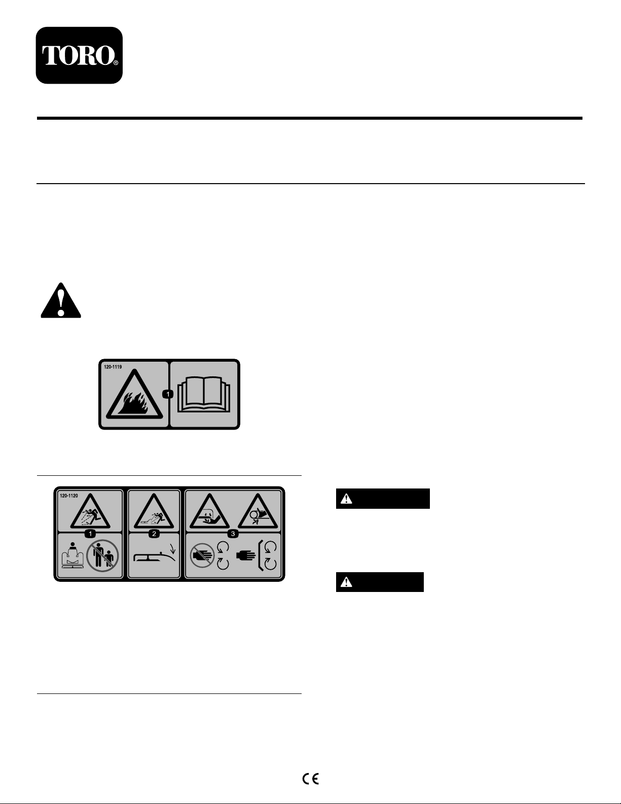
InstallingtheDeckBeltGuards
1.Loosen,butdonotremove,theangenutonthe
outsideofeachsuspensionbracketontherearofthe
deck;seeFigure1.
Figure1
1.Self-tappingscrew(3)3.Flangenut(2)
2.Rightpulleycover
5.Installthemowingdeckontothetractionunitas
describedintheOperator'sManual.
6.Verifythattheguardisclearofallmovingparts
(acrosstheirfullrangeofoperation),thatit
willnotcausedamagetowires,hosesorother
componentsandthatitwillnotinterferewiththe
safeoperationofthetractionunitorthecuttingdeck.
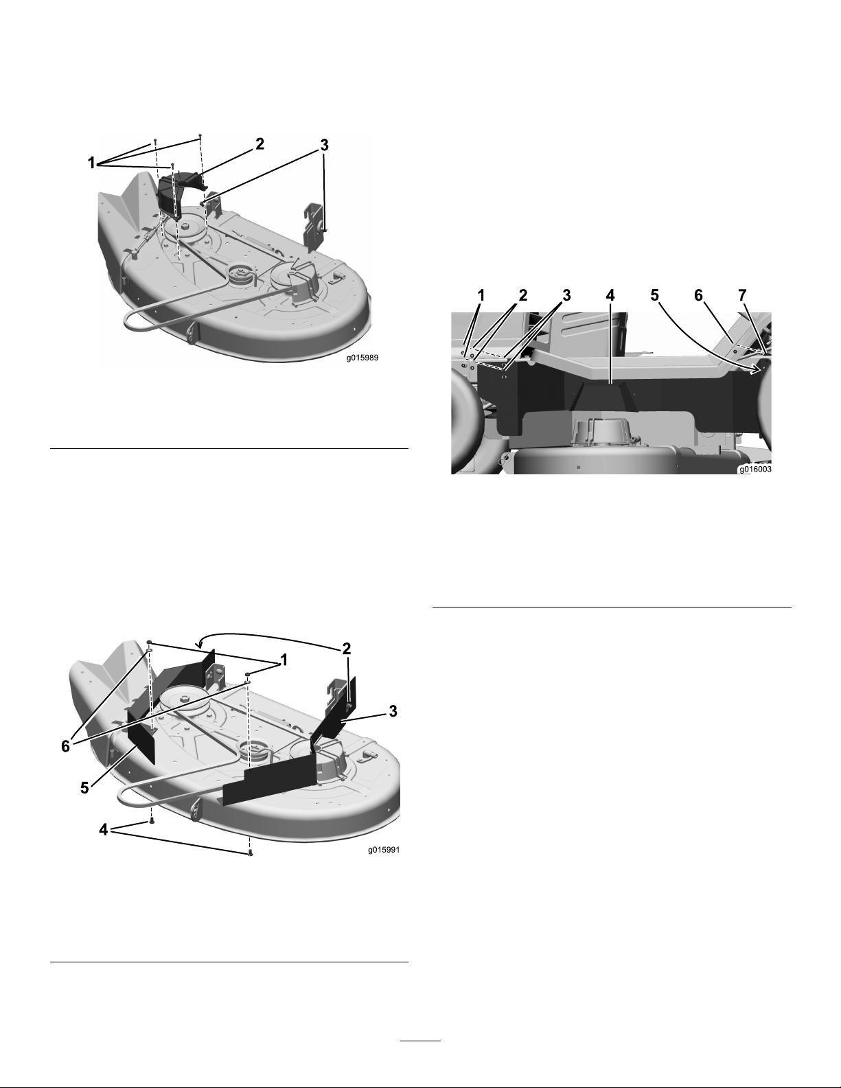
InstallingtheLeftFrameBelt
Guard
1.AttachtheleftframebeltguardasshowninFigure3.
2.Removetherightpulleycoverand3self-tapping
screwsasshowninFigure1.Storethemforfuture
use.
3.Drillaholeinthemowingdeckusingthetemplatein
Figure6,attheendoftheseinstructions,tolocate
thenewhole.
4.Mountbothleftandrightdeckguardstothemowing
deckasshownin
Figure2.
Figure3
1.Locknut(NIM6-1)(2)5.Locknut(NIM6-1)
2.Washer(M6)(2)
3.Hexbolt(M6-1X16),
insertedfrominside(2)
4.Leftframebeltguard
6.Alignholetowireanchor
7.Hexbolt(M6-1X16),
insertedfrominsideframe
2.Drillaholeintheframejustinfrontoftheleftrear
wheel.Usetheholeintheleftframebeltguardasa
guide;seeFigure4.
Important:Thereisabundleofwiresonthe
backsideoftheframewhereyouaredrilling.
Moveitclearofthedrilllocationpriortodrilling
thehole.
Figure2
1.Locknut(NIM8-1.25)(2)4.Hexbolt(M8-1.25X16)(2)
2.Flangenut,existing(2)
3.Leftdeckbeltguard6.Washer(M8)(2)
5.Rightdeckbeltguard
2
Page 3

Figure5
Figure4
1.Drilla6.2mmdiameter
hole
2.Hexbolt(M6-1X16),
insertedfrominsideframe
3.Locknut(NIM6-1)
3.InstallthehexboltandlocknutasshowninFigure4.
4.Verifythattheguardsareclearofeachother,all
movingparts(acrosstheirfullrangeofoperation),
thattheywillnotcausedamagetowires,hosesor
othercomponents,andthattheywillnotinterfere
withthesafeoperationofthetractionunitorthe
mowingdeck.
InstallingtheRightFrameBelt
Guard
1.Attachtherightframebeltguard.UseFigure5as
aguide.
A.Loosen,butdonotremove,the2existingbolts
justbehindtherightfrontwheel.
1.Locknut(NIM6-1)(2)3.Rightframebeltguard
2.Hexbolt(M6-1X16),
insertedfrominsideframe
(2)
4.Bolt,existing(2)
2.Verifythattheguardsareclearofeachother,all
movingparts(acrosstheirfullrangeofoperation),
thattheywillnotcausedamagetowires,hosesor
othercomponents,andthattheywillnotinterfere
withthesafeoperationofthetractionunitorthe
mowingdeck.
B.Attachtherightframebeltguardandtightenall
fastenerssecurely.
3
Page 4

Important:Beforedrilling,measurethedimensionsonthisdiagramtoverifythatitisprintedatthe
correctsize.Mountingtheguardinthewronglocationmayresultinareducedrangeintheheight-of-cut
ordamagetothemachine.
1.Locateareaonthedeck.
2.Placethisedgeofthetemplatetowardsthefrontofthedeck.
Figure6
3.Centerthesemarksontheexistingholes.
4.Drilla6.2mmdiameterhole.
4
 Loading...