

Page 1
FormNo.3368-785RevA
BeltGuardKit
TimeCutter
ModelNo.120-7790
Donotsupplytheseinstructionstothecustomer.
TheseinstructionsareforadealertoinstalladditionalbeltguardsonunitssoldinFrance.
®
ZS5000RidingMower
InstallationInstructions
Safety
SafetyandInstructional
Decals
Safetydecalsandinstructionsareeasily
visibletotheoperatorandarelocated
nearanyareaofpotentialdanger.
Replaceanydecalthatisdamagedor
lost.
120-1119
1.Firehazard—readtheOperator’sManual.
Installation
1
PreparingforInstallation
NoPartsRequired
Procedure
Important:Refertothe
areunfamiliarwiththespecicsofoperatingthis
machinebeforeproceeding.Themanualcontains
importantinformationaboutsafelyoperatingthe
machine.Ifyoudonotknowthisinformation,you
couldseriouslyinjureyourselforothers.
1.Parkthemachineonalevel,smoothsurfacewith
sufcientspacetoaccessbothsidesofthemowing
deck.
WARNING
Operator’ s Man ual
ifyou
©2011—TheToro®Company
8111LyndaleAvenueSouth
Bloomington,MN55420
Registeratwww.T oro.com.
Beforeworkingonthemachine,stoptheengine,
settheparkingbrake,removetheignitionkey,
anddisconnectthesparkplugwire.
CAUTION
Ifyouleavethekeyintheignitionswitch,
someonecouldaccidentlystarttheengineand
seriouslyinjureyouorotherbystanders.
Removethekeyfromtheignitionanddisconnect
thewirefromthesparkplugbeforeyoudoany
maintenance.Setthewireasidesothatitdoes
notaccidentallycontactthesparkplug.
2.Checktheloosepartsbagandverifythatitcontains
allthepartslistedinthisdocument.
3.Removethemowingdeckandslideitoutfrom
underthetractionunit;refertotheOperator’sManual
forthismodel.
OriginalInstructions(EN)
PrintedintheUSA.
AllRightsReserved
Page 2
2
3
AssemblingtheDeckBelt
Guard
Partsneededforthisprocedure:
1
Leftdeckguardplate
1Rightdeckguardplate
1Topdeckguardplate
4
HexBolt(M6-1X16)
4
Locknut(NIM6-1)
Procedure
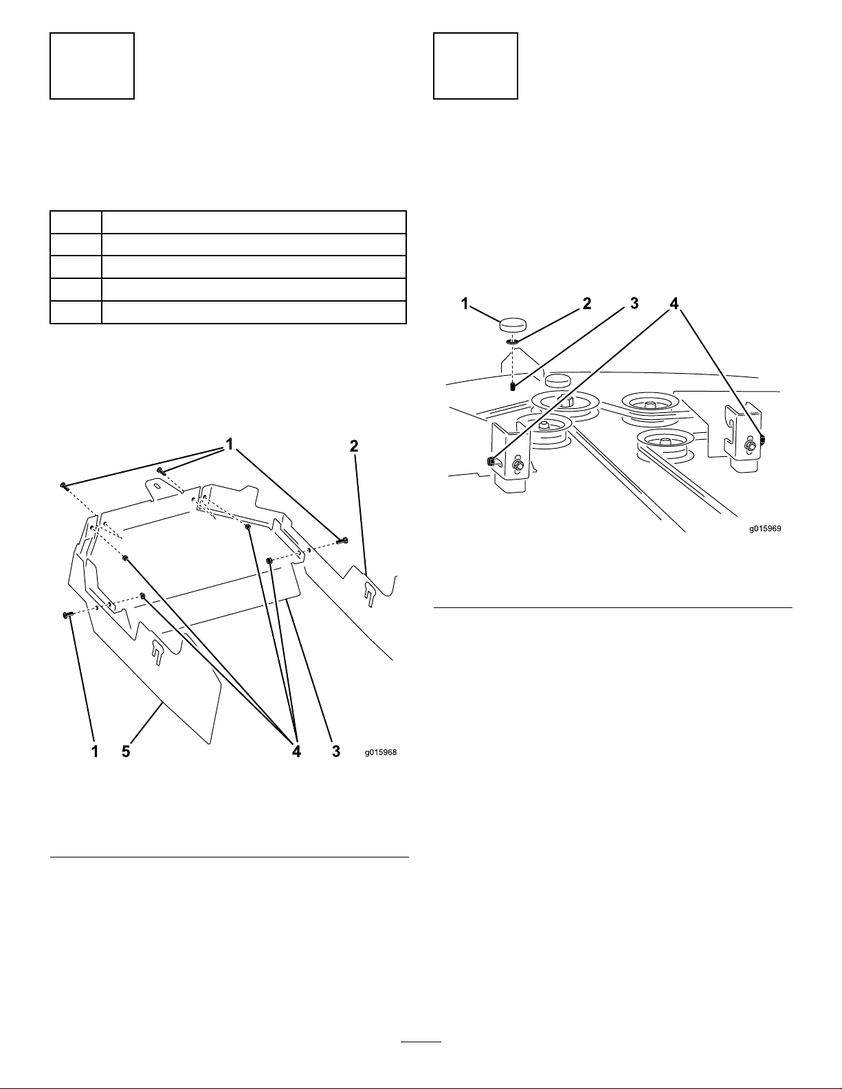
Assembletheleft,rightandtopdeckguardplatesusing
4hexboltsand4locknutsasshowninFigure1.
InstallingtheDeckBeltGuard
NoPartsRequired
Procedure
1.Loosen,butdonotremove,theangenutonthe
outsideofeachsuspensionbracketontherearofthe
deck;seeFigure2.
Figure1
1.HexBolt(M6-1X16)(4)4.Locknut(NIM6-1)(4)
2.Leftdeckguardplate
3.Topdeckguardplate
5.Rightdeckguardplate
Figure2
1.Knob,existing3.Bolt,existing
2.Washer,existing4.Flangenuts
2.Removetheknob,washerandboltshowninFigure2
andsetthemaside.
3.Mounttheassembleddeckbeltguardontothedeck.
A.Attachthetabatthefrontoftheguardtothe
deckusingtheexistingbolt,washerandknob
thatyoujustsetaside;seeFigure3.
2
Page 3

Figure3
1.Washer,existing
2.Knob,existing5.Bolt,existing
3.Flangenut,existing(2)
B.Foreachsideoftheguard,insertthepreviously
loosenedangenutthroughthelargeopening
andslidetheboltintotheslotthattsbest
(Figure3).
C.Tightenbothangenutsandtheknobsecurely.
4.Verifythattheguardisclearofallmovingparts
acrosstheirfullrangeofoperation,thatitwillnot
causedamagetowires,hosesorothercomponents
andthatitwillnotinterferewiththesafeoperation
ofthecuttingdeck.
4.Rearslots,pair(2)
6.Tab
4
AttachingtheDeck
NoPartsRequired
Procedure
1.Slidethedeckbackunderthemachine,mountitto
thetractionunitandadjustitasdescribedinthe
Operator’sManualforthismodel.
2.Verifythatthebeltguardsareclearofallmoving
partsacrosstheirfullrangeofoperation,thatthey
willnotcausedamagetowires,hosesorother
componentsandthattheywillnotinterferewiththe
safeoperationofthemowingdeckandthetraction
unit.
3
Page 4

 Loading...