

Page 1

BeltGuardKit
XLS420TLawnTractor
ModelNo.120-7760
InstallationInstructions
Donotsupplytheseinstructionstothecustomer.
TheseinstructionsareforadealertoinstalladditionalbeltguardsonmachinessoldinFrance.
FormNo.3368-776RevB
Safety
SafetyandInstructional
Decals
Safetydecalsandinstructionsareeasily
visibletotheoperatorandarelocated
nearanyareaofpotentialdanger.
Replaceanydecalthatisdamagedor
lost.
93-6674
1.Crushinghazard,hand—readtheinstructionsbefore
servicingorperformingmaintenance.
Installation
Note:Determinetheleftandrightsidesofthemachine
fromthenormaloperatingposition.
1
PreparingforInstallation
NoPartsRequired
Procedure
Important:Refertothe
areunfamiliarwiththespecicsofoperatingthis
machinebeforeproceeding.Themanualcontains
importantinformationaboutsafelyoperatingthe
machine.Ifyoudonotknowthisinformation,you
couldseriouslyinjureyourselforothers.
1.Parkthemachineonalevel,smoothsurfacewith
sufcientspacetoaccessbothsidesofthemowing
deck.
Operator's Man ual
ifyou
120-1119
1.Firehazard—readtheOperator'sManual.
©2011—TheToro®Company
8111LyndaleAvenueSouth
Bloomington,MN55420
Registeratwww.T oro.com.
2.Levelthemowingdeck;seetheOperator’ sManualfor
thismachine.
3.Lowerthemowingdecktotheshortestcutting
height.
WARNING
Beforeworkingonthemachine,stoptheengine,
settheparkingbrake,removetheignitionkey,
anddisconnectthesparkplugwire.
OriginalInstructions(EN)
AllRightsReserved
Page 2
CAUTION
Ifyouleavethekeyintheignitionswitch,
someonecouldaccidentlystarttheengineand
seriouslyinjureyouorotherbystanders.
Removethekeyfromtheignitionanddisconnect
thewirefromthesparkplugbeforeyoudoany
maintenance.Setthewireasidesothatitdoes
notaccidentallycontactthesparkplug.
4.Checktheloosepartsbagandverifythatitcontains
allthepartslistedinthisdocument.
5.Removethemowingdeckandslideitoutfrom
underthetractionunit;refertotheOperator’ sManual
forthismodel.
2
InstallingtheDeckBeltGuards
Partsneededforthisprocedure:
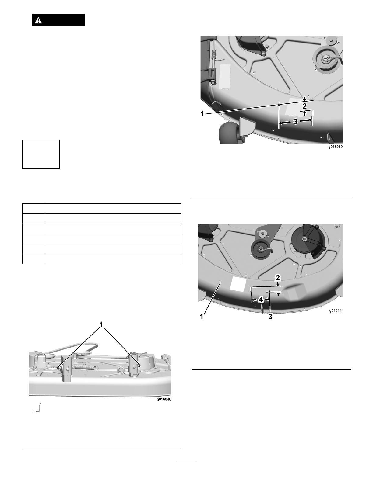
2.Drillaholefortherightdeckbeltguardinthe
mowingdeckasshowninFigure2.
Figure2
1.Drilla5.5mmdiameter
hole.
2.Measure41mmfromthe
endoftheslot.
3.Measure130mmfromthe
sideoftheslot.
1
Leftdeckbeltguard
1Rightdeckbeltguard
2
Self-tappingscrew(M6-3x19)
1
Hexbolt(M6-1X16)
1
Locknut(NIM6-1)
1Washer
Procedure
1.Loosen,butdonotremove,theangenutonthe
outsideofeachsuspensionbracketontherearof
thedeck;see
Figure1.
3.Drillanotherholefortheleftdeckbeltguardinthe
mowingdeckasshownin
1.Holedrilledinprevious
step
2.Measure46mmfromthe
endoftheslot.
Figure3.
Figure3
3.Drilla5.5mmdiameter
hole.
4.Measure149mmfromthe
sideoftheslot.
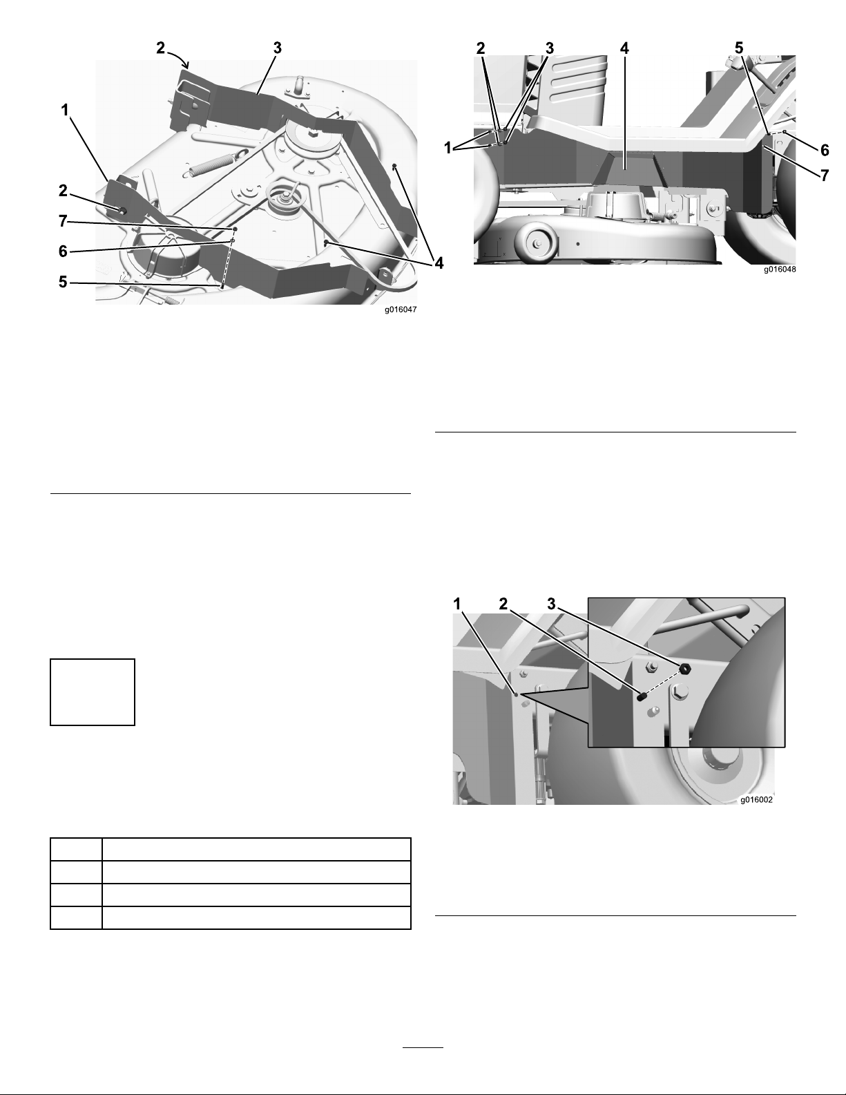
4.Mountbothleftandrightdeckguardstothemowing
deckasshowninFigure4.
1.Flangenut(2)
Figure1
2
Page 3
5
6
7
2
1
3
4
2
g016047
2
1
3 4
5
6
g016048
7
Figure5
Figure4
1.Rightdeckbeltguard
2.Flangenut,existing(2,
onenotshown)
3.Leftdeckbeltguard7.Washer(M6)
4.Self-tappingscrew
(M6-3X19),inserted
fromabove(2)
5.Hexbolt(M6-1X16),
insertedfrombelow
6.Locknut(NIM6-1)
5.Installthemowingdeckontothetractionunitas
describedintheOperator'sManual.
6.Verifythattheguardsareclearofallmovingparts
acrosstheirfullrangeofoperation,thatitwillnot
causedamagetowires,hosesorothercomponents
andthatitwillnotinterferewiththesafeoperation
ofthetractionunitorthemowingdeck.
1.Locknut(NIM6-1)(2)5.Hexbolt(M6-1X16),
2.Washer(M6)(2)6.Locknut(NIM6-1)
3.Hexbolt(M6-1X16),
insertedfrominsideframe
(2)
4.Leftframebeltguard
insertedfrominsideframe
7.Openholeinleftframe
beltguard
2.Drillaholeintheframejustinfrontoftheleftrear
wheel.Usetheopenholeintheleftframebeltguard
asaguide;seeFigure6.
Important:Thereisabundleofwiresonthe
backsideoftheframewhereyouaredrilling.
Moveitclearofthedrilllocationpriortodrilling
thehole.
3
InstallingtheLeftFrameBelt
Guard
Partsneededforthisprocedure:
Procedure
1.AttachtheleftframebeltguardasshowninFigure5.
1
4
4
2
Leftframebeltguard
Hexbolt(M6-1X16)
Locknut(NIM6-1)
Washer(M6)
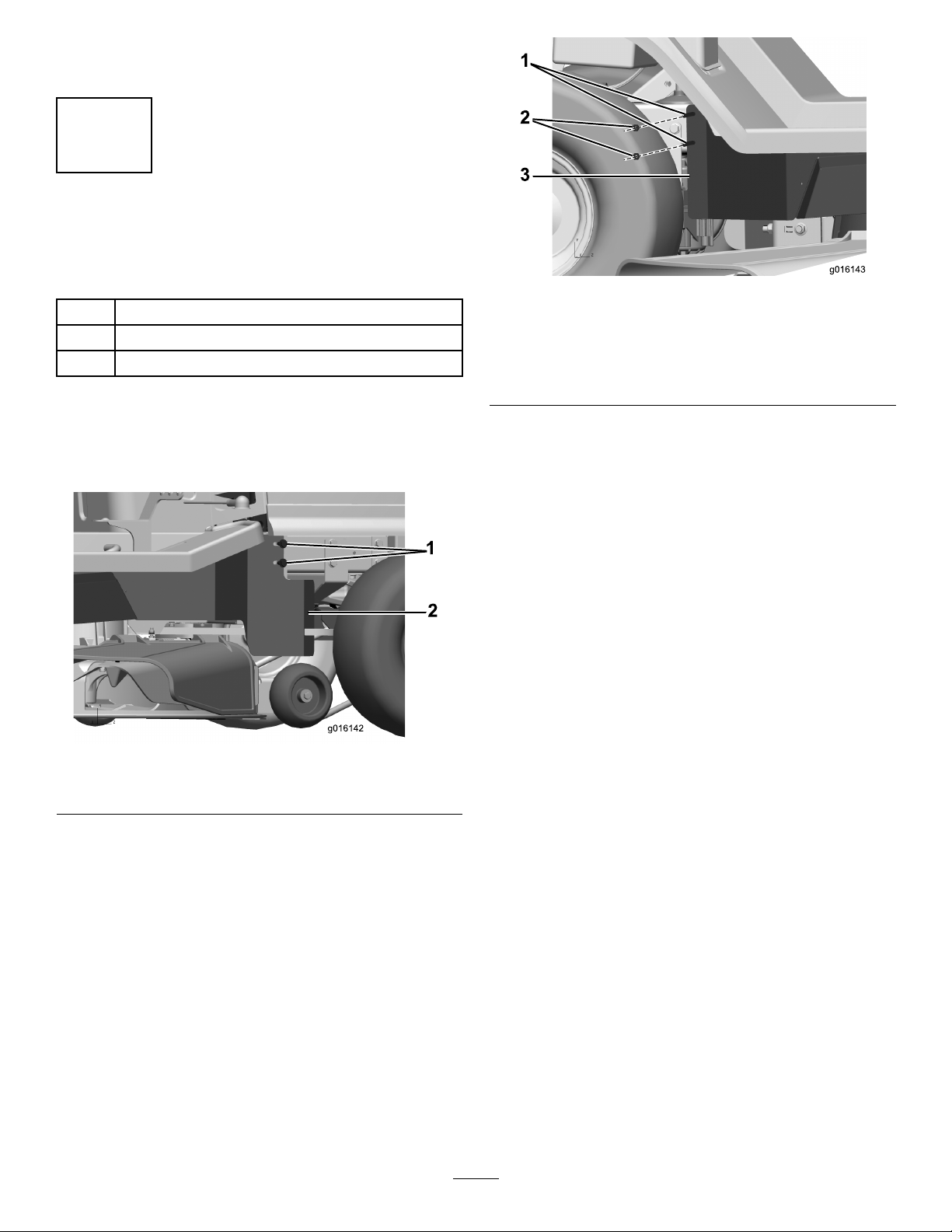
1.Drilla6.2mmdiameter
hole
2.Hexbolt(M6-1X16),
insertedfrominsideframe
Figure6
3.Locknut(NIM6-1)
3.InstallthehexboltandlocknutasshowninFigure6.
4.Verifythattheguardsareclearofallmovingparts
acrosstheirfullrangeofoperation,thatitwillnot
causedamagetowires,hosesorothercomponents
3
Page 4
andthatitwillnotinterferewiththesafeoperation
ofthetractionunitorthemowingdeck.
4
InstallingtheRightFrameBelt
Guard
Partsneededforthisprocedure:
1
Rightframebeltguard
2
Hexbolt(M6-1X16)
2
Locknut(NIM6-1)
1.Hexbolt(M6-1X16),
insertedfrominsideframe
(2)
2.Locknut(NIM6-1)(2)
Figure8
3.Rightframebeltguard
Procedure
1.Attachtherightframebeltguardasshownin
Figure7andFigure8.
Figure7
1.Bolt,existing(2)2.Rightframebeltguard
A.Loosen,butdonotremove,the2existingbolts
intheframejustbehindtherightfrontwheel.
B.Attachtherightframebeltguardandtightenall
fastenerssecurely.
2.Verifythattheguardsareclearofallmovingparts
acrosstheirfullrangeofoperation,thatitwillnot
causedamagetowires,hosesorothercomponents
andthatitwillnotinterferewiththesafeoperation
ofthetractionunitorthemowingdeck.
4
 Loading...