

Page 1
BaggerFinishingKit
2011andAfterTITANZX6000SeriesZero-Turn-RadiusRiding
Mower
ModelNo.120-7126
ThiskitrequirestheBaggerKittocompletetheinstallation.Contact
anAuthorizedServiceDealerorCustomerServicetoobtainthe
necessaryparts.Formoreinformation,gotowww.Toro.com.
Safety
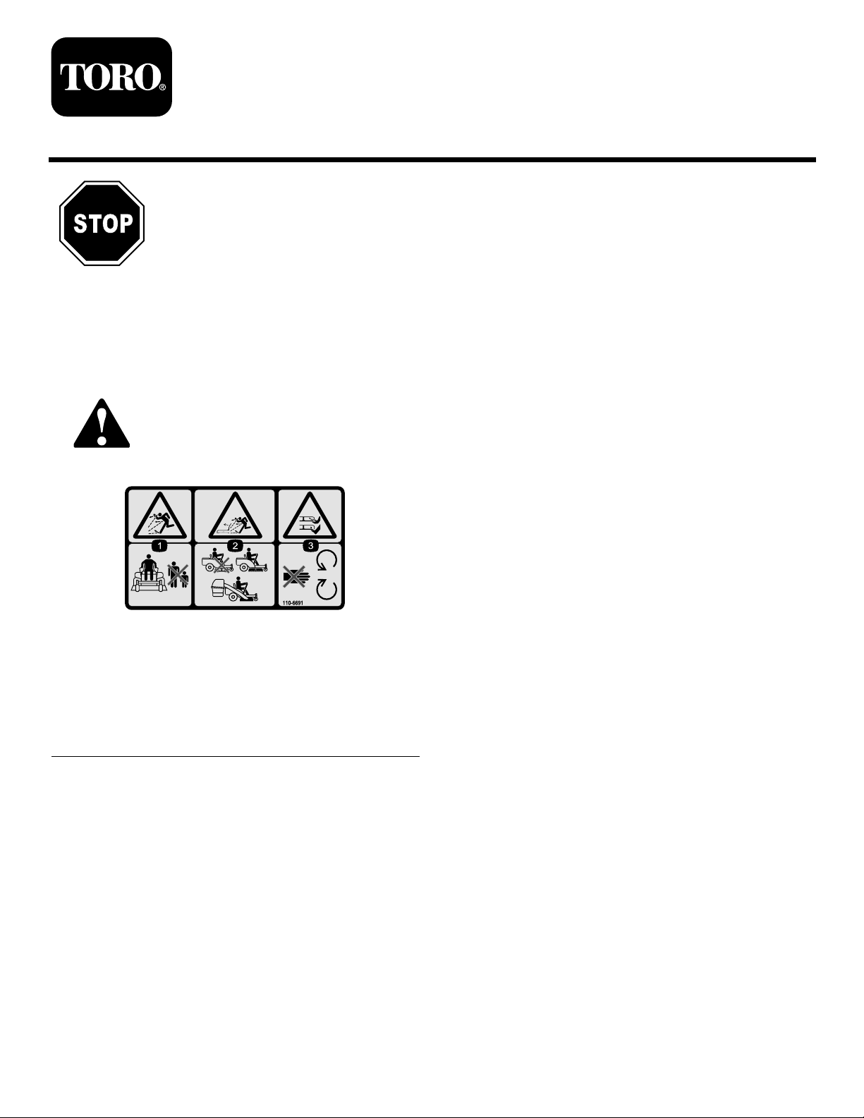
SafetyandInstructionalDecals
Safetydecalsandinstructionsareeasilyvisibletotheoperatorandarelocatednearanyareaof
potentialdanger.Replaceanydecalthatisdamagedorlost.
FormNo.3368-669RevA
InstallationInstructions
110-6691
1.Thrownobjecthazard—keepbystandersasafedistance
fromthemachine.
2.Thrownobjecthazard,mower—donotoperatewithoutthe
deector,dischargecover ,orgrasscollectionsystemin
place.
3.Cutting/dismembermentofhandorfoot—stayawayfrom
movingparts.
©2011—TheToro®Company
8111LyndaleAvenueSouth
Bloomington,MN55420
Registeratwww.T oro.com.
OriginalInstructions(EN)
PrintedintheUSA
AllRightsReserved
Page 2
Installation
1
InstallingtheBaggerSupport
andBaggerFrame
Partsneededforthisprocedure:
1Baggersupport
1
Baggerframeassembly
1
Supportspacerplate(fromtheBaggerKit)
Selftappingscrew(5/16x3/4inch)(fromtheBagger
2
Kit)
2
Bolt(5/16x2-1/2inch)(fromtheBaggerKit)
2
Locknut(5/16inch)(fromtheBaggerKit)
1
Clevispin(1/2x2-1/4inch)(fromtheBaggerKit)
5
Hairpincotter(fromtheBaggerKit)
2
Rod(fromtheBaggerKit)
4
Washer(fromtheBaggerKit)
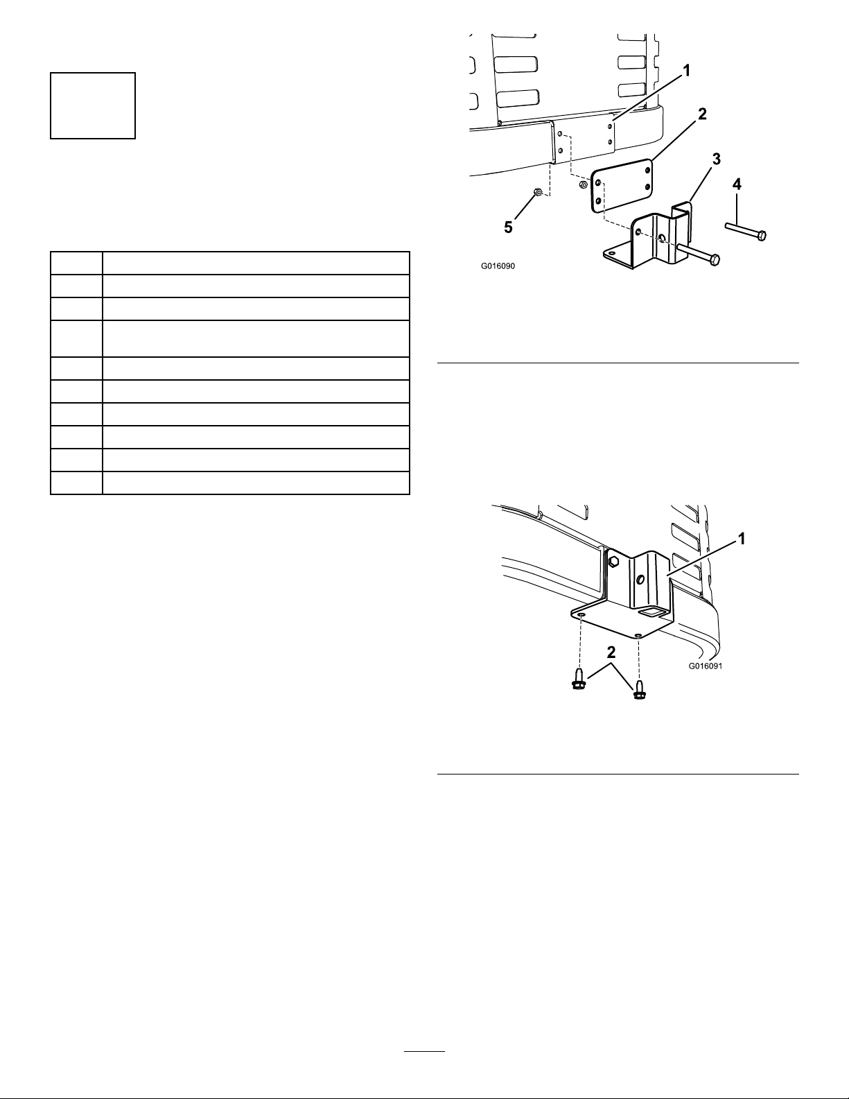
Figure1
1.Machineframe4.Bolt(5/16x2-1/2inch)
2.Supportspacerplate5.Locknut(5/16inch)
3.Supportbracket
3.Securetheplateandbrackettotheframeusing2
bolts(5/16x2-1/2inch)and2locknuts(5/16inch)
(Figure1).
4.Securethesupportbrackettothebottomofthe
machineframefrombelowusing2self-tapping
screws(5/16x3/4inch)asshownin
Figure2.
Procedure
Important:ThisstepsupersedesStep1(Installing
theBaggerFrame)intheSetupsectionofthe
Bagger
Thisbaggernishingkitincludesanewbaggerframe
assemblyandanewsupportbracketformachineswith
a60-inchmowingdeck.Replacethebaggerframe
assemblyandsupportbracketincludedinthebaggerkit
withthesenewparts.
1.Locatethebaggerframesupportspacerplateand
2.Installtheplateandbrackettothemachineframeas
Operator’ s Man ual
bracketinlooseparts.
shownin
Figure1.
.
Figure2
1.Supportbracket2.Selftappingscrews(5/16
x3/4inch)
5.Removetheexistingfastenersthatsecurethe
rectangularspacerplatefromthetopoftheengine
frame,andremovetheplate(Figure3).
2
Page 3
G010581
1
2
3
4
5
6
4
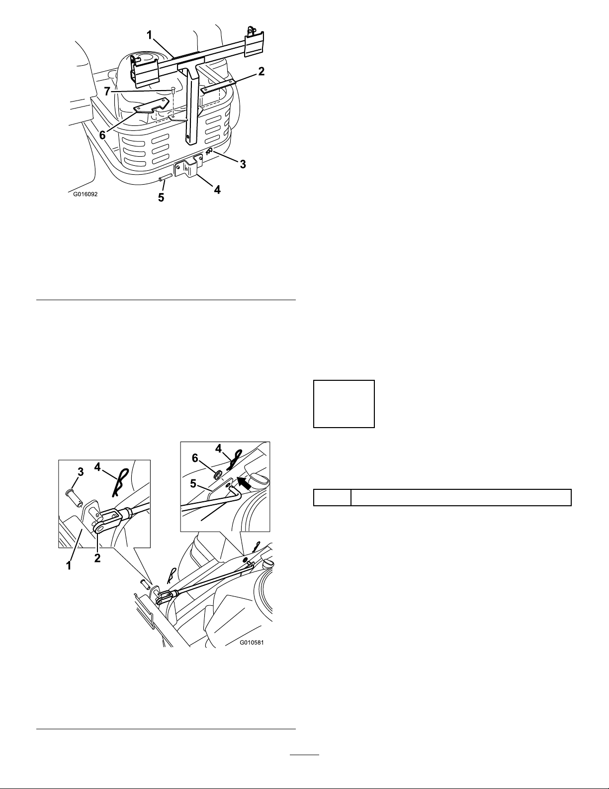
10.Insertthebentendsoftherodintothemachine
frameasshowninFigure4,andsecuretheendof
therodwithawasherandahairpincotter.
11.Adjustthesupportrodssothatthebaggerframeis
heldsecuretothemachineframeandseatsinthe
notchoftheanglespacerplateinstalledpreviously .
12.Repeatthesestepsforeachsupportrod:
A.Loosenthejamnutatthebaseoftheclevisend
oftherod.
B.Rotatetheclevisendoftherodtoadjusttherod
tothedesiredlength.
Figure3
1.Baggerframe5.Clevispin(1/2x2-1/4
2.Spacerplate,rectangular
(existing)
3.Hairpincotter7.Fasteners,existing
4.Supportbracket
inch)
6.Spacerplate,angle(new)
6.Installthenewanglespacerplateasshownin
Figure3usingthefastenersremovedpreviously.
7.Securethebaggerframetothesupportbracketwith
aclevispin(1/2x2-1/4inch)andahairpincotter
(Figure3).
8.Installtwosupportrods,onetoeachsideofthe
baggerframe.
9.Locatetheexistingbracketbetweenthereardrive
wheelandframe(Figure4).
C.Aligntheholesintheclevisendwiththeholein
thebaggerframeattheattachmentpoint.
D.Securetheclevisendoftherodstothebagger
frameusingaclevispinandahairpincotter
Figure4).
(
E.Tightenthejamnut.
13.Withbothrodsinstalledandattached,checkthe
baggerframeforplay.
Note:Thebaggerframeshouldbeheldtightto
themachineframe.Ifnecessary,repeattheprevious
steptosecurethebaggerframe.
2
InstallingtheBlades
Partsneededforthisprocedure:
3
Hi-Liftblade
Procedure
1.Removetheexistingmowerbladesinstalledonyour
deck.RefertotheRemovingtheBladessectionin
theOperator’sManualformoreinformation.
Figure4
Leftsideshown
1.Baggerframe
2.Clevisend5.Bracketonframe
3.Clevispin
4.Hairpincotter
6.Washer
2.InstalltheHi-Liftmowerbladeslocatedinloose
parts.RefertotheInstallingtheBladessectioninthe
Operator’sManualformoreinformation.
3
Page 4

3
2
G010632
1
2
3
4
5
6
G010701
1
2
3
4
InstallingtheWeight
Partsneededforthisprocedure:
1Weight
1Adhesivebumperpad
1Rod
4Flatwasher
2Hairpincotter
8
Spacer
Procedure
Figure6
1.Weight4.Rod
2.Adhesivebumperpad
3.Spacers(8)6.Washer(4)
5.Hairpincotter(2)
3.Installtheweighttothefrontofthemachineframe
(Figure6).
Note:Thisprocedureisonlyformachineswitha
ROPS.MachineswithoutaROPSdonotrequireafront
weights.
1.Removethe2nutsand2boltsthatsecurethefront
ofthemowerhousingpan(Figure5).
Note:Savethenutsandboltstosecurethefrontof
themowerhousingpanlater.
Figure5
1.Nut(2)
2.Bolt(2)
3.Mowerhousingpan
2.Installtheadhesivebumpertotheweight(Figure6).
4.Securetheweightwitharod,8spacers,4washers,
and2hairpincottersasshownin
Figure6.
Note:Whenyouinstalltheweight,allowittorest
onthefrontlipoftheundersideofthemachine
frameasshowninFigure7.Thissuspendsthe
weightwhileyousecureittothemachine.Becareful
nottodislodgetheweightwhenyouinstallthe
supportingrod.
Figure7
1.Cutawayofthefrontofthe
machineframe
2.Bumper4.Resttheweighthere
3.Weight
duringinstallation
Note:Wheneveryouremovethebagger
attachment,removetheweighttorestoretheproper
stabilitytothemachine.
5.Installthefrontofthemowerhousingpanusingthe
nutsandboltsthatyouremovedinstep1.
4
Page 5

4
G013095
1
2
3
4
5
G013096
1
2
3
4
5
6
7
8
9
10
InstallingtheChute
Partsneededforthisprocedure:
1
Angledcutoffbafe
1
Curvedbafe
2
Locknut(5/16inch)
1Handknob
1Washer
1
Chute
Procedure
Figure8
1.Deectorassembly4.Carriagebolt(existing;
reuse)
2.Locknut(existing;retain)5.Carriagebolt(existing;
retain)
3.Locknut(existing,reuse)
WARNING
Anuncovereddischargeopeningcouldallowthe
lawnmowertothrowobjectsintheoperatoror
bystander’sdirectionandresultinseriousinjury.
Also,contactwiththebladecouldoccur.
Neveroperatethelawnmowerunlessyouinstall
acoverplate,amulchplate,oragrasschuteand
catcher.
Neveroperatethemowerwiththedischargeopening
uncovered.Alwaysuseadischargecover,mulchcover,
orbaggingchutewhenoperatingthemowerdeck.
1.Removefastenersthatsecurethedeectorassembly
tothedeck(
Note:Retainallfasteners.
Figure8).
2.Removethedeectorassembly.
Note:Retainallpartstoconvertthedecktoside
discharge.
3.Locateandinstalltheangledcutoffbafetothedeck
attherearholesinthemowerdeck(Figure9).
Note:Usetheexistingfastenersfromthatlocation
tosecuretheangledcutoffbafetothedeck.
1.Holeinfrontwallofthe
deck
2.Locknut
3.Horizontalpost,curved
bafe
4.Verticalpost,curvedbafe9.Locknut(existing;reuse)
5.Curvedbafe10.Center,forwardholein
4.Installthecurvedbafetothedeck(Figure9).
5
Figure9
6.Highliftblade
7.Carriagebolt(existing;
reuse)
8.Angledcutoffbafe
mowerdeck
Page 6

A.Aligntheverticalpostinthecurvedbafe
G013097
1
2
3
4
5
6
G013098
1
2
withcenter,forwardholeinthedeckandthe
horizontalpostwiththeholeinthefrontwall
ofthemowerdeck.
B.Securehorizontalposttothefrontwallofthe
deckusingalocknut.
5.Installthechutetothedeck.
Note:Ensurethattheopeningintopofthechute
alignswiththeexposedpostonthedecktopandthe
forwardverticalplatemateswiththefoldedmetal
bracketofthechute(
Figure10).
Figure11
1.Retainingclasp2.Flexiblelatch
5
ConnectingwiththeDischarge
Tube
NoPartsRequired
Procedure
1.Slidethecurvedendofthedischargetube(supplied
withthebaggerkit)intotheopeninginthebagger
Figure12).
top(
Figure10
1.Dischargechute4.Foldedmetalbracket,
2.Handknob5.Forwardverticalplate,
3.Washer6.Exposedpostinthedeck,
6.Installawasherandhandknoboverthepostcoming
throughthechutetop(
7.Handtightentheknobtosecurethechutetothe
deck.
8.Hooktheexiblelatchonthechutetotheretaining
claspweldedtothesidewallofthedeck(Figure11).
chute
deck
curvedbafe
Figure10).
6
Page 7

G010641
1
2
3
4
5
1.Dischargetube,curved
G013095
1
2
3
4
5
end
2.Openinginbaggertop
3.Dischargetube,aredend
Figure12
Maintenance
RemovingtheFinishingKit
Wheneveryouremovethebaggerkit,removethe
nishingkitusingthefollowingprocedure.Retainall
partsforfutureinstallation.
1.Removethedischargetubefromthemachineand
installthedischargecover.
WARNING
Anuncovereddischargeopeningcouldallowthe
lawnmowertothrowobjectsintheoperatoror
bystander’sdirectionandresultinseriousinjury.
Also,contactwiththebladecouldoccur.
Neveroperatethelawnmowerunlessyouinstall
acoverplate,amulchplate,oragrasschuteand
catcher.
4.Peg
5.Rubberstrap
2.Slidethearedendofthedischargetubeoverthe
endofthechute(Figure12).
3.Movetherubberretainingstraponthechutesnaps
overthepegonthedischargetubetosecureit
Figure12).
(
Figure13
1.Deectorassembly4.Carriagebolt(existing;
2.Locknut(existing;retain)5.Carriagebolt(existing;
3.Locknut(existing;reuse)
reuse)
retain)
2.Replacethemowerblades.
•RemovetheHi-Liftmowerbladesinstalledon
yourdeck;refertotheRemovingtheBlades
sectionintheOperator’sManualformore
information.
•Installthestandardmowerbladesremoved
previously;refertotheInstallingtheBlades
sectionintheOperator’sManualformore
information.
7
Page 8

 Loading...