

Page 1
FormNo.3369-688RevA
48and54inchBaggerFinishingKit
2011andAfterTITANSeriesZero-Turn-RadiusRidingMower
ModelNo.120-7122
ModelNo.120-7123
InstallationInstructions
ThiskitrequirestheBaggerKit79326tocompleteinstallation.For
allTITANSeriesmowers,beginFinishingKitinstallationbefore
installingthebaggerkit.ContactyourAuthorizedServiceDealer
orToroCustomerServicetoobtainthenecessaryparts.Formore
information,visitusatwww.Toro.com.
Safety
Important:TheROPSrollbarisanintegraland
effectivesafetydevice.Keeptherollbarinthe
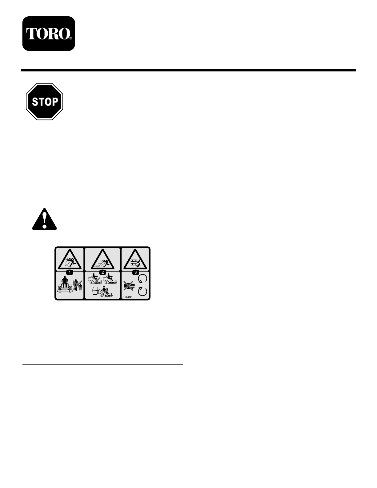
SafetyandInstructionalDecals
Safetydecalsandinstructionsareeasilyvisibletotheoperatorandarelocatednearanyareaof
potentialdanger.Replaceanydecalthatisdamagedorlost.
110-6691
1.Thrownobjecthazard—keepbystandersasafedistance
fromthemachine.
2.Thrownobjecthazard,mower—donotoperatewithoutthe
deector,dischargecover,orgrasscollectionsystemin
place.
3.Cutting/dismembermentofhandorfoot—stayawayfrom
movingparts.
fullyraisedandlockedpositionwhenoperatingthe
mower.Lowertherollbartemporarilyonlywhen
absolutelynecessary.
©2011—TheToro®Company
8111LyndaleAvenueSouth
Bloomington,MN55420
Registeratwww.Toro.com.
OriginalInstructions(EN)
PrintedintheUSA.
AllRightsReserved
Page 2
Installation
G016271
1
2
3
4
5
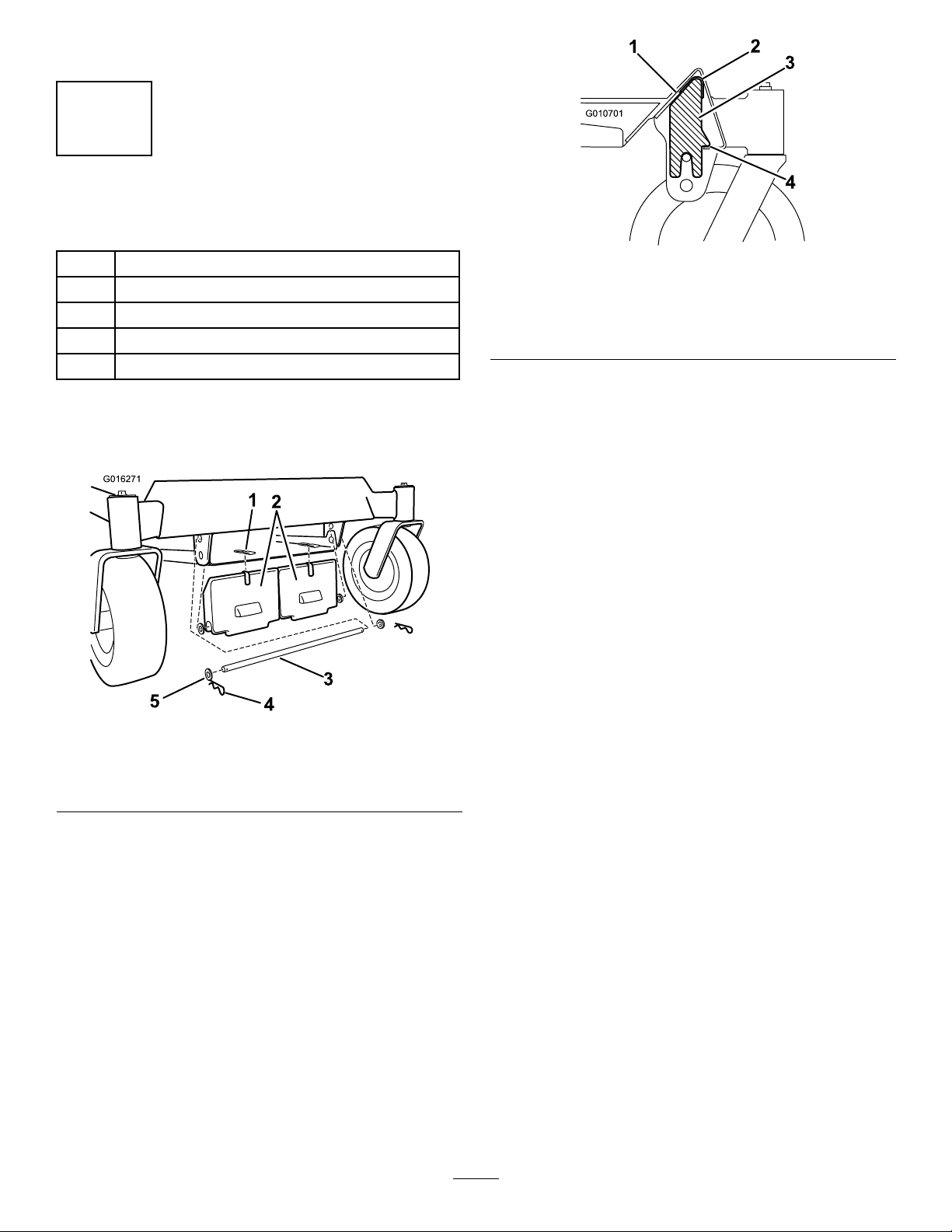
G010701
1
2
3
4
1
InstallingtheWeight
Partsneededforthisprocedure:
2Weight
2Adhesivebumper
1Rod
4Washer
2Hairpin
Procedure
1.Installanadhesivebumpertotheweight(Figure1).
Figure2
1.Cutawayofthefrontofthe
machineframe
2.Bumper4.Resttheweighthere
Important:Wheneveryouremovethebagger
attachment,remembertoremovethefrontweight
toreturntheproperstabilitytothemachine.
3.Weight
duringinstall
Figure1
1.Adhesivebumper4.Hairpin
2.Frontweight5.Washer
3.Rod
Note:OnTitanMXunits,disconnectthefront
deckpanfromtheframetoallowinstallationofthe
weights.Ensurethepanisinstalledoncetheweights
aresecured.
2.Installtheweighttothefrontofthemachineframe.
Securetheweightwitharod,fourwashers,andtwo
hairpinsasshownin
Note:Wheninstallingthefrontweightallowitto
restonthefrontlipoftheundersideofthemachine
frameasshownFigure2.Thiswillsuspendthe
weightwhileyousecureittothemachine.Use
carenottodislodgetheweightwheninstallingthe
supportingrod.
Figure1.
2
Page 3
2
G016262
G016263
G016264
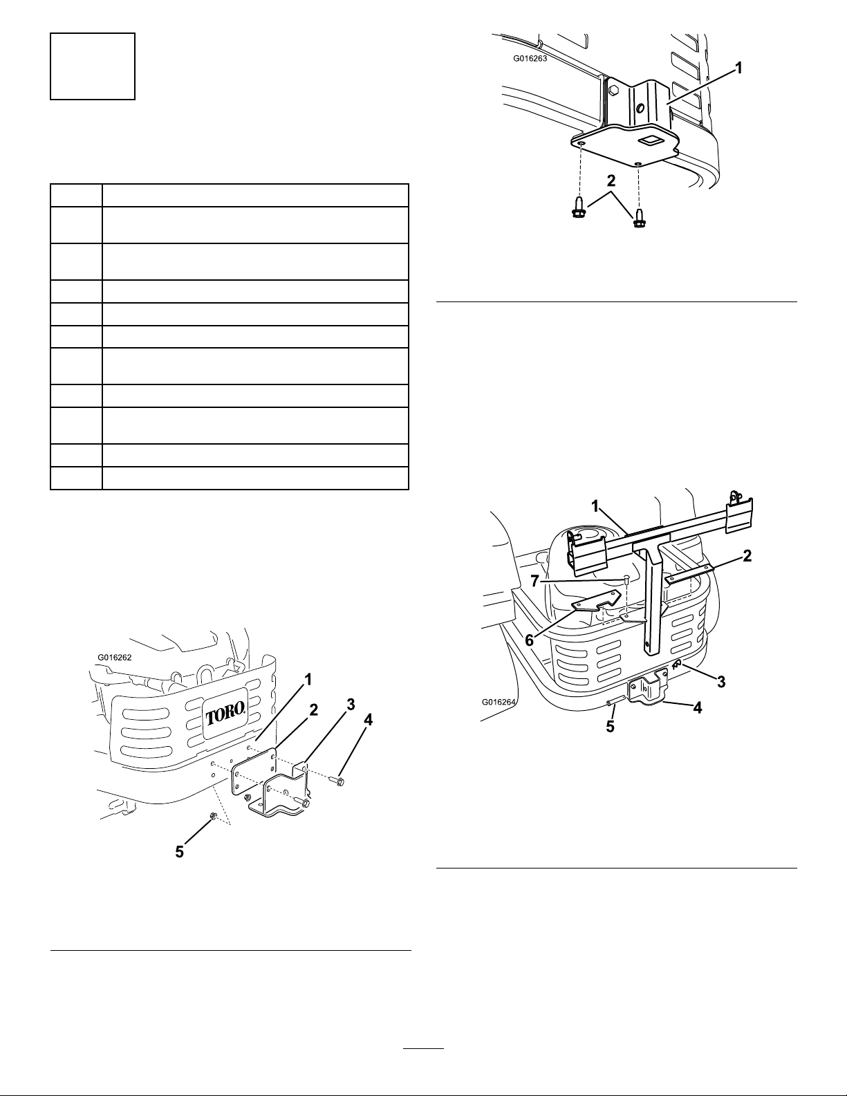
InstallingtheBaggerFrame
Partsneededforthisprocedure:
1
Baggerframe(discardframeinbaggerkit)
Baggerframesupportbracket(discardbracketin
1
baggerkit)
Selftappingscrew(5/16x3/4inch)(includedin
2
baggerkit)
4Hairpincotter—IncludedinBaggerKit79326
2Rod—IncludedinBaggerKit79326
4Washer—IncludedinBaggerKit79326
Bolt(5/16x2-1/2inch)—IncludedinBaggerKit
2
79326
2
Locknut(5/16inch)—IncludedinBaggerKit79326
Clevispin(1/2x2-1/4inch)—IncludedinBagger
1
Kit79326
1
Spacerplate—IncludedinBaggerKit79326
1Angledplate—IncludedinBaggerKit79326
Figure4
1.Supportbracket2.Selftappingscrews(5/16
x3/4inch)
3.Removetheexistingfastenerssecuringthe
rectangularspacerplatefromthetopoftheengine
frameandremovetheplate.
4.Installthenewanglespacerplateasshownin
Figure4usingthefastenersremovedpreviously.
5.Installthebaggerframetothesupportbracket.
Securethebaggerframewithaclevispin(1/2x
2-1/4inch)andhairpincotter(Figure5).
Procedure
1.Locatethebaggerframebracket.Installthebracket
tothemachineframeasshownin
thebrackettotheframeusingtwobolts(5/16x
2-1/2inch)andtwolocknuts(5/16inch).
Figure3
1.Machineframe4.Bolt(5/16x2-1/2inch)
2.Supportspacerplate5.Locknut(5/16inch)
3.Supportbracket
Figure3.Secure
Figure5
1.Baggerframe5.Clevispin(1/2x2-1/4
2.Spacerplate,rectangular
(existing)
3.Hairpin7.Fasteners,existing
4.Supportbracket
inch)
6.Spacerplate,angle(new)
6.Installtwosupportrods,onetoeachsideofthe
baggerframe.Locatetheexistingbracketbetween
thereardrivewheelandframe(Figure6).
2.Securethesupportbrackettothebottomofthe
machineframefrombelowusingtwoselftapping
screws(5/16x3/4inch)asshowninFigure4.
3
Page 4

G010581
1
2
3
4
5
6
4
Figure6
Leftsideshown
1.Baggerframe
2.Clevisend5.Bracketonframe
3.Clevispin
4.Hairpin
6.Washer
3
InstallingtheChute
Partsneededforthisprocedure:
1
Straightbafe(48inchdecksonly)
1
Curvedbafe(54indecksonly)
1
Locknut(5/16inch)
1Handknob
1Washer
1
Chute
Procedure
UsethisprocedurewheninstallingtheFinishingKiton
machineswithboth48and54inchdecks.
7.Insertthebentendoftherodintothebaggerframe
asshowninFigure6.Securetheendoftherodwith
awasherandhairpin.
8.Adjustthesupportrodssothatbaggerframeisheld
securetothemachineframeandseatsinthenotch
oftheanglespacerplateinstalledpreviously.Repeat
thesestepsforeachsupportrod:
A.Loosenthejamnutatthebaseoftheclevisend
oftherod.
B.Rotatetheclevistoadjusttherodtothedesired
length.
C.Aligntheholesintheclevisendwiththeholein
thebaggerframeattheattachmentpoint.
D.Securetheclevisendtothebaggerframeusinga
clevispinandhairpincotter.(
Figure6).
E.Tightenthejamnut.
9.Withbothrodsinstalledandattached,checkthe
baggerframeforplay.Thebaggerframeshouldbe
heldtighttothemachineframe.Ifnecessary,repeat
theprevioussteptosecurethebaggerframe.
10.Forremainingsteps,consultBaggerKit79326
Owner’ s Man ual
,beginningatInstallationstep
2.
WARNING
Anuncovereddischargeopeningcouldallowthe
lawnmowertothrowobjectsintheoperatoror
bystander’sdirectionandresultinseriousinjury.
Also,contactwiththebladecouldoccur.
Neveroperatethelawnmowerunlessyouinstall
acoverplate,amulchplate,oragrasschuteand
catcher.
Neveroperatethemowerwiththedischargeopening
uncovered.Adischargecover,mulchcoverorbagging
chutemustalwaysbeusedwhenthemowerdeckis
operated.
1.Removefastenerssecuringthedeectorassembly
andexistingcutoffbafetothedeck(
Retainallfasteners.Removethefastenersplugging
theforwardhole.
Figure7).
4
Page 5

G010637
1
2
2
3
4
5
6
7
Figure7
1
2
3
4
5
6
7
G015685
G010638
1
2
3
4
5
6
1.Deectorassembly5.Locknut(existing)
2.Fasteners(existing),retain
3.Carriagebolt(existing)
4.Cutoffbafe(existing)
6.Forwardhole
7.Frontretainingclasp
2.Removethedeectorassemblyandreinstallthecut
offbafe.Retainallpartstoconvertthedeckto
sidedischarge.
4.Installthechutetothedeckmakingsuretheopening
intopofthechutealignswiththeexposedposton
thedecktop(Figure9).
Figure9
1.Dischargechute
2.Handknob
3.Washer
4.Postincurvedbafe,
forwardhole
5.Frontexiblelatch
6.Openinginthetopofthe
chute
3.Installabafetodeck(Figure8).For48inch
decks,useastraightbafe.For54inchdecks,
useacurvedbafe.Aligntheverticalpostinthe
bafewithforwardholeinthedeck.Rotatethe
bafeuntilthehorizontalpostalignswiththehole
inthefrontwallofthedeck.Secureittothefront
wallofthedeckusingalocknut.
5.Installawasherandhandknoboverthepostcoming
throughthechutetop.Handtightentosecurethe
chutetothedeck.
6.Hookthefrontexiblelatchonthechutetothe
retainingclaspweldedtothefrontwallofthedeck
Figure10).Hooktheexiblelatchonthebackof
(
thechutetotheretainingclaspweldedtotherear
wallofthedeck.
Figure10
Figure8
1.Retainingclasp5.Horizontalpost
2.Forwardhole6.Locknut
3.Bafe
4.Verticalpost
7.Frontwallhole
1.Flexiblelatchandretainingclasp
5
Page 6

4
G016265
G005672
1
2
3
4
G005757
InstallingtheBaggerTop
Partsneededforthisprocedure:
1
Circularcotterpin
Procedure
1.Installthebaggertoptothebaggerframe.Slide
thebracketsoverthepostsinthebaggerframeand
installthecircularcotterintotheholeintheright
handpost(
totheoperatingposition.Thebaggertopiseasierto
installiftwopeopleworktogether.
Note:Toremovethecircularcotter,continueto
rotateitinthesamedirectionasinstalled.
Figure11).Rotatethebaggertopdown
2.Liftthebaggertopandinstallthebagsbysliding
thebagframehooksontotheretainingbrackets
(Figure12).
1.Baggertop
2.Baggerframe
3.Bracket,baggertop
Figure11
Figure12
1.Bag3.Retainingbracket
2.Baggerframe4.Bagframehook
3.Lowerthebaggertopontothebag(Figure13).
Figure13
4.Circularcotterpin
5.Post
6
Page 7

5
G010641
1
2
3
4
5
6
ConnectingwiththeDischarge
Tube
NoPartsRequired
Procedure
1.Slidethecurvedendofthedischargetubeintothe
openinginthebaggertop(
Figure14).
InstallingtheBlades
Partsneededforthisprocedure:
3
Hi-Liftblade
Procedure
1.Removetheexistingmowerbladesinstalledonyour
deck.RefertotheRemovingtheBladessectionin
theOperator’ sManualformoreinformation.
2.InstalltheHi-Liftmowerbladeslocatedinloose
parts.RefertotheInstallingtheBladessectioninthe
Operator’sManualformoreinformation.
Figure14
1.Dischargetube,curved
end
2.Openinginbaggertop
3.Dischargetube,aredend
2.Slidethearedendofthedischargetubeoverthe
endofthechute.Movetherubberretainingstrapon
thechutesnapsoverthepegonthedischargetube
tosecureit(Figure14).
4.Peg
5.Rubberstrap
7
Page 8

Maintenance
G010637
1
2
2
3
4
5
6
7
RemovingtheFinishingKit
Wheneverthebaggerkitisremoved,thenishingkit
shouldberemovedusingthefollowingprocedure.
Retainallpartsforfutureinstallation.
CAUTION
Removingthebaggerchangestheweight
distributionofthemachine.Operatingthemachine
withthefrontweightsinstalledwithoutthebagger
maycauseanunstableconditionwhichcouldresult
inalossofcontrol.
Ensurethefrontweightsareproperlyremoved
beforeoperatingthemachinewithoutthebagger
attachment.
1.Removethefrontweights.Removethefastener
securingtheweighttothemachine.Takecareto
controltheweightasthesupportrodisremoved.
Figure15
1.Deectorassembly5.Locknut(existing),reuse
2.Fasteners(existing),retain
3.Carriagebolt(existing),
reuse
4.Cutoffbafe(existing)
6.Forwardhole
7.Frontretainingclasp
2.Removethedischargetubefromthemachineinstall
andthedischargecover(
Figure15).
WARNING
Anuncovereddischargeopeningcouldallowthe
lawnmowertothrowobjectsintheoperatoror
bystander’sdirectionandresultinseriousinjury.
Also,contactwiththebladecouldoccur.
Neveroperatethelawnmowerunlessyouinstall
acoverplate,amulchplate,oragrasschuteand
catcher.
3.Replacethemowerblades.
•RemovetheHi-Liftmowerbladesinstalled
onyourdeck.RefertotheRemovingthe
BladessectionintheOperator’sManualformore
information.
•Installthestandardmowerbladesremoved
previously.RefertotheInstallingtheBlades
sectionintheOperator’sManualformore
information.
Important:TheROPSrollbarisanintegraland
effectivesafetydevice.Keeptherollbarinthe
fullyraisedandlockedpositionwhenoperatingthe
mower.Lowertherollbartemporarilyonlywhen
absolutelynecessary.
8
 Loading...