

Page 1
BeltGuardKit
DH200SeriesLawnTractor
ModelNo.120-1 190
Donotsupplytheseinstructionstothecustomer.
TheseinstructionsareforadealertoinstalladditionalbeltguardsmandatedbytheFrenchgovernment.
FormNo.3368-455RevA
InstallationInstructions
Safety
SafetyandInstructional
Decals
Safetydecalsandinstructionsareeasily
visibletotheoperatorandarelocated
nearanyareaofpotentialdanger.
Replaceanydecalthatisdamagedor
lost.
120-1119
1.Firehazard—readtheOperator’sManual.
Installation
1
PreparingforInstallation
NoPartsRequired
Procedure
Important:Refertothe
areunfamiliarwiththespecicsofoperatingthis
machinebeforeproceeding.Themanualcontains
importantinformationaboutsafelyoperatingthe
machine.Ifyoudonotknowthisinformation,you
couldseriouslyinjureyourselforothers.
1.Parkthemachineonalevel,smoothsurfacewith
sufcientspacetoaccessbothsidesofthemowing
deck.
2.Lowerthemowingdecktotheshortestcutting
height.
Operator’ s Man ual
ifyou
©2011—TheT oro®Company
8111LyndaleAvenueSouth
Bloomington,MN55420
Registeratwww.T oro.com.
WARNING
Beforeworkingonthemachine,stoptheengine,
settheparkingbrake,removetheignitionkey,
anddisconnectthesparkplugwire.
CAUTION
Ifyouleavethekeyintheignitionswitch,
someonecouldaccidentlystarttheengineand
seriouslyinjureyouorotherbystanders.
Removethekeyfromtheignitionanddisconnect
thewirefromthesparkplugbeforeyoudoany
maintenance.Setthewireasidesothatitdoes
notaccidentallycontactthesparkplug.
3.Supporttherearaxleonbothsidesandremoveboth
rearwheels.
OriginalInstructions(EN)
PrintedintheUSA.
AllRightsReserved
Page 2
2
InstallingtheDeckGuard
Partsneededforthisprocedure:
1Deckbeltguard
2
Bolt(M5x12)
2
Washer(M5.3)
2
Locknut(M5)
Procedure
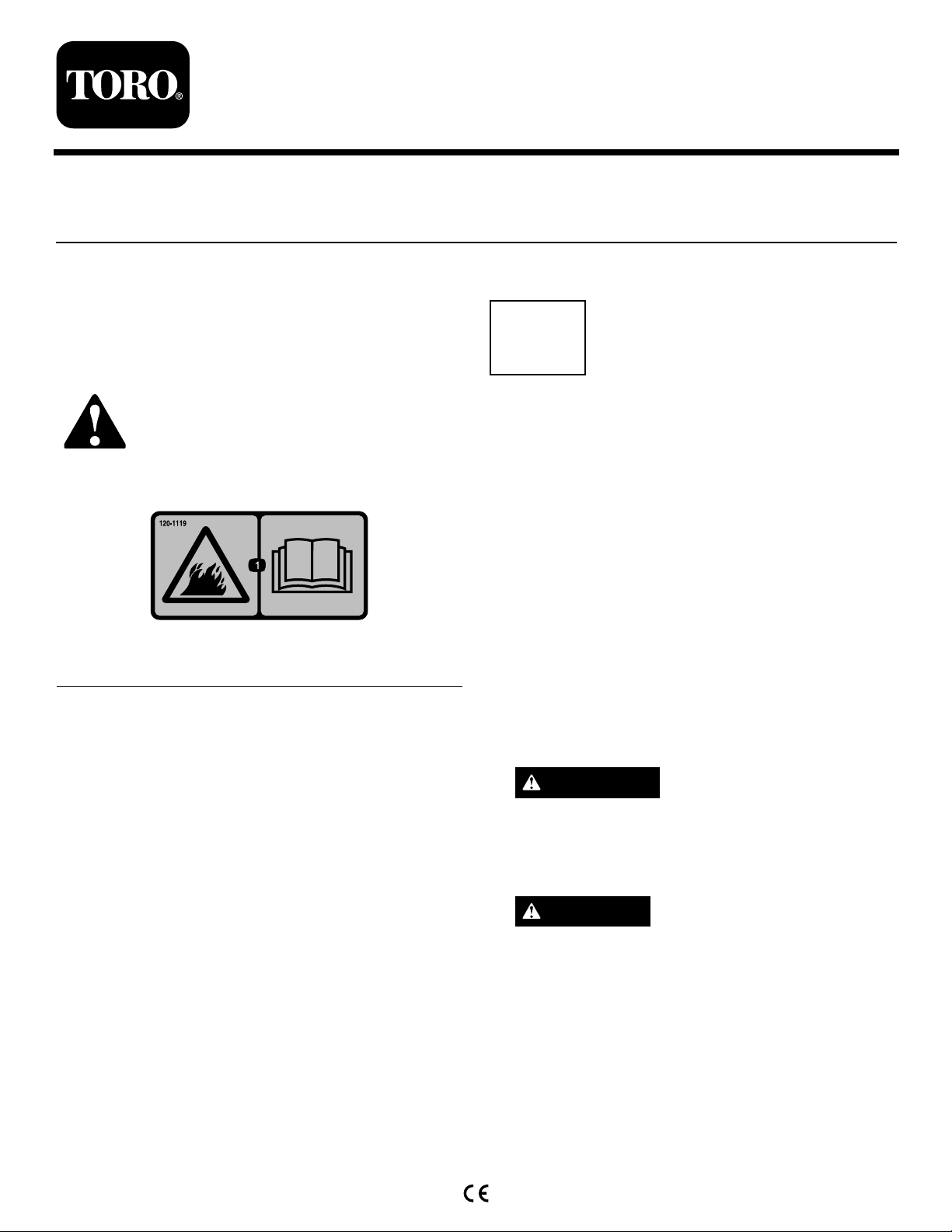
1.RemovethebeltfromthePTOclutchandtheidler
tensionspringfromtheidlerpulley(Figure1).
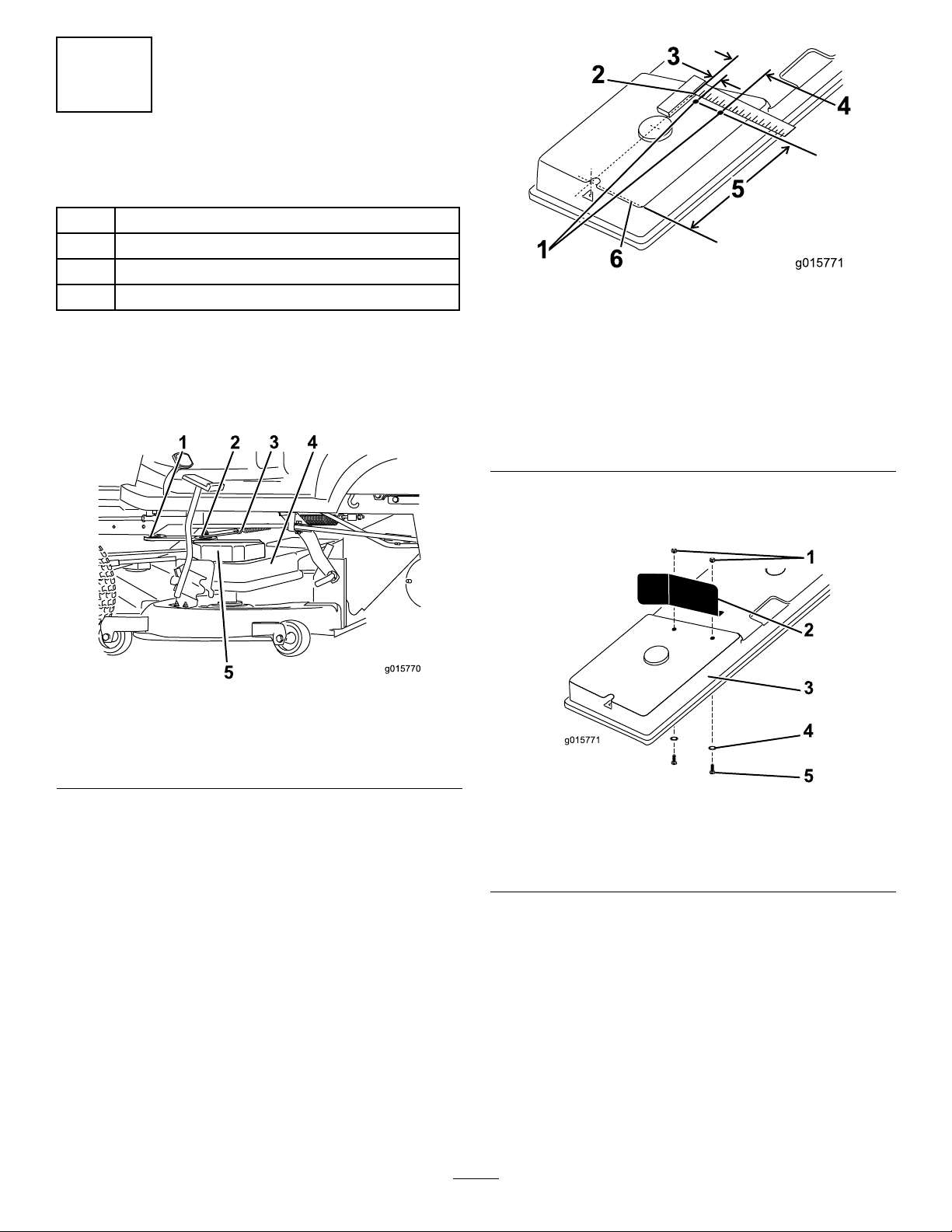
Figure2
1.Drill5.5mmdiameter(2)
2.Measuredimensions
3and4fromtheline
betweenthecenterofthe
rightboltholeandthe
centerofthespindle.
3.16mm
4.90mm
5.256mm(2)
6.Measuredimension5from
thecenterlineoftheright
bolthole.
6.Mountthedeckguardtothedeckcoverasshown
inFigure3.
Figure1
1.PTOclutch
2.Idlerpulley5.Pulleycoverandpulley
3.Idlertensionspring
4.Deckcover
2.Removetheidlerpulley.
3.Removethepulleycoverandthepulleyunderit
fromtheleftsideofdeckbeltcover(Figure1).
4.Removethedeckbeltcoverfromthedeck.
5.Drill2holesinthetopofthedeckbeltcover
(Figure2).
Figure3
1.Locknut(M5)4.Washer(M5.3)
2.Deckguard
3.Deckcover
5.Bolt(M5x12)
7.Assemblethedeck.
8.Raisethedecktothetallestheight-of-cutand
verifythatthenewlyinstalledguardclearsallwires,
switchesandbeltsandwillnotinterferewiththesafe
operationofthetractionunitorthecuttingdeck.
2
Page 3

3
InstallingtheLeftBeltGuard
Partsneededforthisprocedure:
1
Leftbeltguard
1
Hexbolt(M8-1.25x12)
1
Washer(M8)
1
Locknut(NIM8-1.25)
2
Self-tappingscrew(M4.2x13)
Procedure
1.Ontheleftsideofthemachine,drill2holesas
speciedinFigure4.
Figure5
Fastenersandattachmentpointsfortheleftbeltguard
1.Locknut(NIM8-1.25)4.Locknut,existing(2)
2.Washer(M8)5.Self-tappingscrew(M4.2
3.Hexbolt(M8-1.25x12)
x13)(2)
Note:Theinstalledleftbeltguardshouldappearas
shownin
Figure6.
Figure4
Measurementsfordrillingholesinthepulleybracket
1.Pulleybracket
2.25mm4.35mm
3.3.6mmdiameter(2)
2.Removethe2locknutslocatedatbothsupportson
theundersideofthefootrest.
3.Installtheleftbeltguard.
Note:UsethefastenersshowninFigure5.
Figure6
Theleftbeltguardinstalled
1.Cutoutforsteeringlinkage3.Cutoutforthefuelline
2.Cutoutforparkingbrake4.Guardpassesbetween
thebag-on-demandpedal
andthepulleycover
4.Verifythattheguardisclearofallmovingparts
acrosstheirfullrangeofoperation,thatitwillnot
causedamagetowires,hosesorothercomponents
andthatitwillnotinterferewiththesafeoperation
ofthetractionunitorthecuttingdeck.
3
Page 4

4
InstallingtheRightBeltGuard
Partsneededforthisprocedure:
1Rightbeltguard
1
Hexbolt(M8-1.25x12)
1
Washer(M8)
1
Locknut(NIM8-1.25)
5
Self-tappingscrew(M4.2x13)
Procedure
1.Ontherightsideofthemachine,drillholesinthe
pulleybracket,intherearfootrestsupportandinthe
frontsectionoftheframe(
Figure7).
Figure8
Measurementstodrillholeintherearfootrestsupport
1.3.4mmdiameter3.50mm
2.11mm
C.Drilltheholesinthefrontframeasspeciedin
Figure9.
Figure9
Measurementstodrillholesinthefrontframe
Figure7
1.Pulleybracket
2.Rearfootrestsupport6.Washer(M8)
3.Frontframesection7.Hexbolt(M8-1.25x12)
4.Locknut(NIM8-1.25)8.Self-tappingscrew(M4.2
5.Self-tappingscrew(M4.2
x13)(2)
x13)(3)
A.Measurethelocationfortheholesinthepulley
bracketasspeciedin
Figure4.
B.Fortheholeintherearfootrestsupport,usethe
measurementsinFigure8.
1.3.4mmdiameter(2)
2.10mm4.152.5mm
3.25mm
2.Positiontherightbeltguardbehindthetraction
pedalassemblyandtheswitchmountedbehindit
andattachittotheframeofthemachineasshown
inFigure10.
Figure10
1.Rightbeltguard2.Tractionpedalassembly
3.Verifythattheguardisclearofallmovingparts
acrosstheirfullrangeofoperation,thatitwillnot
causedamagetowires,hosesorothercomponents
andthatitwillnotinterferewiththesafeoperation
ofthetractionunitorthecuttingdeck.
4
 Loading...