

Page 1
FormNo.3368-770RevA
BeltGuardKit
DH140SeriesLawnTractor
ModelNo.120-1 180
InstallationInstructions
Donotsupplytheseinstructionstothecustomer.
TheseinstructionsareforadealertoinstalladditionalbeltguardsformachinessoldinFrance.
Safety
SafetyandInstructional
Decals
Safetydecalsandinstructionsareeasily
visibletotheoperatorandarelocated
nearanyareaofpotentialdanger.
Replaceanydecalthatisdamagedor
lost.
120-1119
1.Firehazard—readtheOperator’sManual.
Installation
LooseParts
Usethechartbelowtoverifythatallpartshavebeenshipped.
Description
Nopartsrequired
Leftbeltguard
Self-tappingscrew(M4.2x13)
Beltguardcover1
Self-tappingscrews(M4.2x13)
Rightbeltguard1
Self—tappingscrews(M4.2x13)
Hexbolt(M4x10)
Washer(M4.3)
Hexnut(M4)
Qty.
Use
–
1
4
2
4
2
2
2
Prepareforinstallation.
Installtheleftbeltguard.
Installthebeltguardcover.
Installtherightbeltguard.
©2011—TheToro®Company
8111LyndaleAvenueSouth
Bloomington,MN55420
Registeratwww.T oro.com.
OriginalInstructions(EN)
PrintedintheUSA.
AllRightsReserved
Page 2
PreparingforInstallation
Important:Refertothe
Operator’ s Man ual
areunfamiliarwiththespecicsofoperatingthis
machinebeforeproceeding.Themanualcontains
importantinformationaboutsafelyoperatingthe
machine.Ifyoudonotknowthisinformation,you
couldseriouslyinjureyourselforothers.
1.Parkthemachineonalevel,smoothsurfacewith
sufcientspacetoaccessbothsidesofthemowing
deck.
2.Lowerthemowingdecktotheshortestcutting
height.
WARNING
Beforeworkingonthemachine,stoptheengine,
settheparkingbrake,removetheignitionkey,
anddisconnectthesparkplugwire.
CAUTION
Ifyouleavethekeyintheignitionswitch,
someonecouldaccidentlystarttheengineand
seriouslyinjureyouorotherbystanders.
ifyou
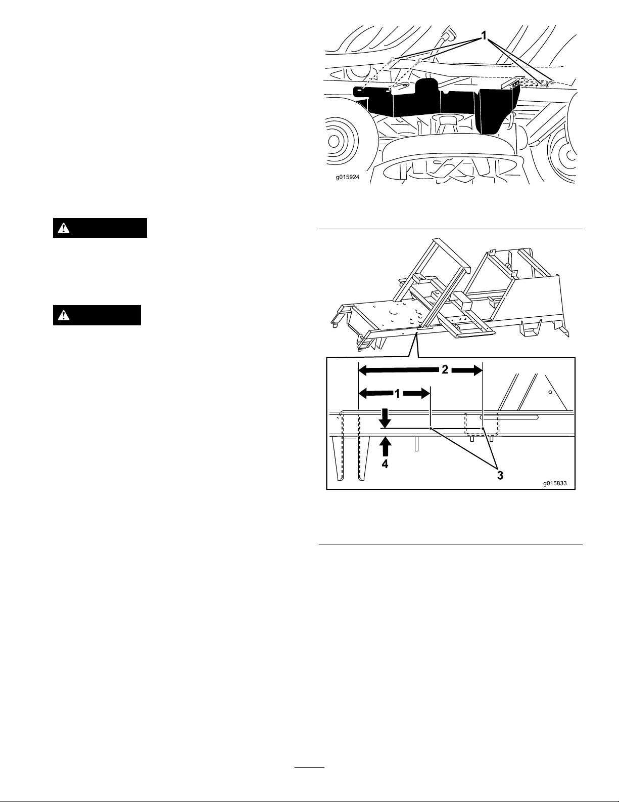
Figure1
1.Self-tappingscrew(M4.2x13)(4)
Removethekeyfromtheignitionanddisconnect
thewirefromthesparkplugbeforeyoudoany
maintenance.Setthewireasidesothatitdoes
notaccidentallycontactthesparkplug.
3.Supporttherearaxleonbothsidesandremoveboth
rearwheels.
InstallingtheLeftBeltGuard
1.Ontheleftsideofthemachine,disconnectthe
steeringlinkage.
2.Drill4holeswithadiameterof3.4mminthe
locationsshowninFigure1,Figure2andFigure3.
Installtheleftbeltguardusingthefastenerslisted
inFigure1.
Figure2
1.148mm
2.257mm4.15.5mm
3.3.4mmdiameter(2)
2
Page 3

Figure5
1.40mm3.12mm
2.145mm4.3.4mmdiameter
Figure3
1.8.5mm3.32mm
2.53.5mm
4.3.4mmdiameter(2)
3.Verifythattheguardisclearofallmovingparts
acrosstheirfullrangeofoperation,thatitwillnot
causedamagetowires,hosesorothercomponents
andthatitwillnotinterferewiththesafeoperation
ofthetractionunitorthecuttingdeck.
4.Attachtheleftrearwheel.
InstallingtheBeltGuardCover
Ontherightsideofthemachine,drill2holeswitha
diameterof3.4mminthelocationsshowninFigure4
andinstallthebeltguardcoverusingthefastenerslisted.
InstallingtheRightBeltGuard
1.Ontherightsideofthemachine,drill4holeswith
adiameterof3.4mminthelocationsshownin
Figure6,Figure7,Figure8andFigure9.Installthe
rightbeltguardusingthefastenerslistedinFigure6.
Figure6
1.Hexbolt(M4x10)(2)3.Hexnut(M4)(2)
2.Washer(M4.3)(2)4.Self—tappingscrews
(M4.2x13)(4)
Figure4
1.Self-tappingscrews(M4.2x13)(2)
3
Page 4

Figure7
1.15mm3.77.5mm
2.3.4mmdiameter(2)
4.105.5mm
Figure9
1.17mm3.158mm
2.3.4mmdiameter
2.Verifythattheguardisclearofallmovingparts
acrosstheirfullrangeofoperation,thatitwillnot
causedamagetowires,hosesorothercomponents
andthatitwillnotinterferewiththesafeoperation
ofthetractionunitorthecuttingdeck.
3.Attachtherightrearwheel.
Figure8
1.3.4mmdiameter3.23mm
2.18mm
4
 Loading...