

Page 1
Preface
The purpose of this publication is to provide the service
technician with information for troubleshooting, testing
and repair of major systems and components on the
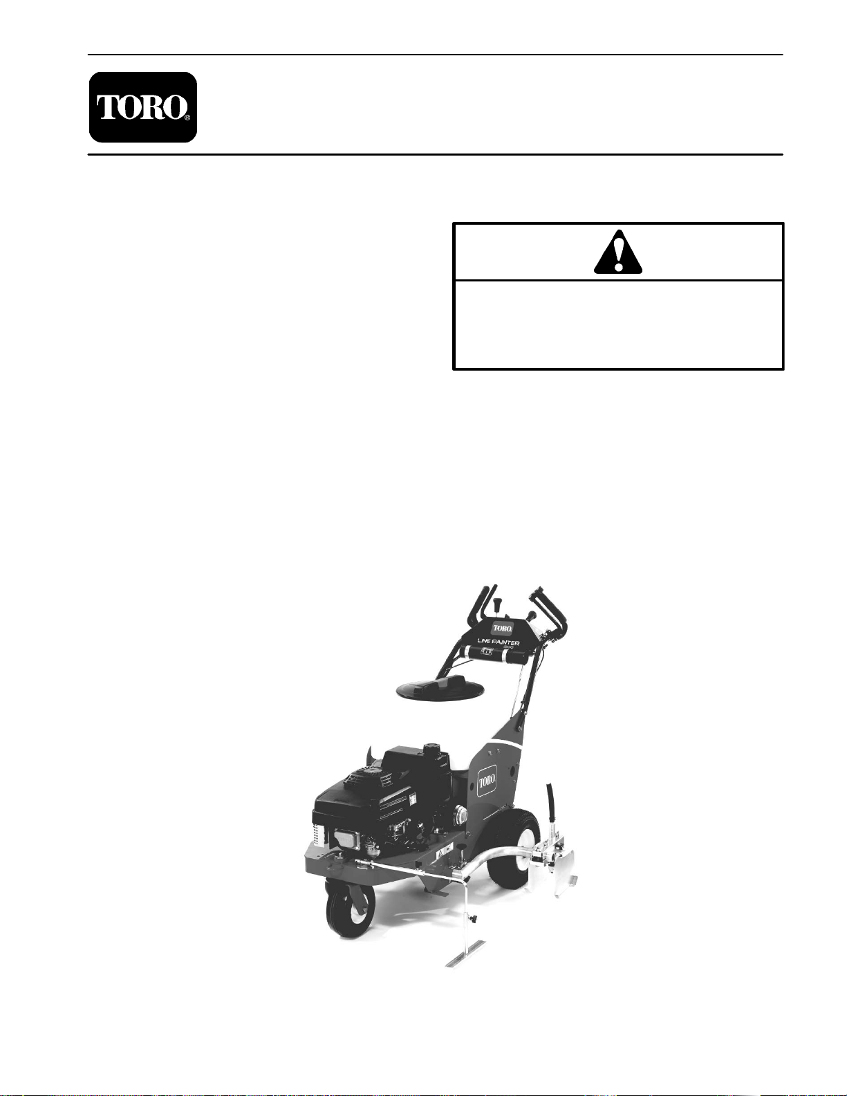
Line Painter 1200.
REFER TO THE OPERATOR’S MANUALS FOR OPERATING, MAINTENANCE AND ADJUSTMENT
INSTRUCTIONS. Space is provided in Chapter 2 of this
book to insert the Operator’s Manuals and Parts Cata
logs for your machine. Replacement Operator’s Manuals are available on the internet at www.toro.com or by
sending complete Model and Serial Number to:
The Toro Company
Attn. Technical Publications
8111 Lyndale Avenue South
Minneapolis, MN 55420
The Toro Company reserves the right to change product
specifications or this publication without notice.
-
Part No. 05144SL Rev. A
Service Manual
Line Painter 1200
This safety symbol means DANGER, WARNING,
or CAUTION, PERSONAL SAFETY INSTRUCTION. When you see this symbol, carefully read
the instructions that follow. Failure to obey the
instructions may result in personal injury.
NOTE: A NOTE will give general information about the
correct operation, maintenance, service, testing or re
pair of the machine.
IMPORTANT: The IMPORTANT notice will give important instructions which must be followed to prevent damage to systems or components on the
machine.
-
E The Toro Company – 2005, 2007
Page 2

This page is intentionally blank.
Line Painter 1200
Page 3

Table Of Contents
Chapter 1 – Safety
Safety Instructions . . . . . . . . . . . . . . . . . . . . . . . . . . 1 – 2
Safety and Instruction Decals . . . . . . . . . . . . . . . . 1 – 4
Chapter 2 – Product Records and Maintenance
Product Records
Maintenance . . . . . . . . . . . . . . . . . . . . . . . . . . . . . . . 2 – 1
Equivalents and Conversions . . . . . . . . . . . . . . . . 2 – 2
Torque Specifications . . . . . . . . . . . . . . . . . . . . . . . 2 – 3
Chapter 3 – Gasoline Engine
Introduction
Specifications . . . . . . . . . . . . . . . . . . . . . . . . . . . . . . 3 – 3
General Information . . . . . . . . . . . . . . . . . . . . . . . . 3 – 4
Service and Repairs . . . . . . . . . . . . . . . . . . . . . . . . 3 – 5
KAWASAKI FJ180V SERVICE MANUAL
Chapter 4 – Electrical System
Electrical Schematic
Special Tools . . . . . . . . . . . . . . . . . . . . . . . . . . . . . . 4 – 3
Troubleshooting . . . . . . . . . . . . . . . . . . . . . . . . . . . . 4 – 4
Component Testing . . . . . . . . . . . . . . . . . . . . . . . . . 4 – 5
. . . . . . . . . . . . . . . . . . . . . . . . . . . 2 – 1
. . . . . . . . . . . . . . . . . . . . . . . . . . . . . . . . 3 – 2
. . . . . . . . . . . . . . . . . . . . . . . . 4 – 2
Chapter 5 – Paint System
Specifications
Paint Schematic . . . . . . . . . . . . . . . . . . . . . . . . . . . . 5 – 3
Circuit Operation . . . . . . . . . . . . . . . . . . . . . . . . . . . 5 – 4
Troubleshooting . . . . . . . . . . . . . . . . . . . . . . . . . . . . 5 – 8
General Information . . . . . . . . . . . . . . . . . . . . . . . . 5 – 9
Adjustments . . . . . . . . . . . . . . . . . . . . . . . . . . . . . . 5 – 10
Service and Repairs . . . . . . . . . . . . . . . . . . . . . . . 5 – 12
Chapter 6 – Chassis and Controls
Specifications
Adjustments . . . . . . . . . . . . . . . . . . . . . . . . . . . . . . . 6 – 3
Service and Repairs . . . . . . . . . . . . . . . . . . . . . . . . 6 – 6
Chapter 7 – Traction Drive System
Service and Repairs
DANA MODEL 4360 TEARDOWN AND ASSEMBLY
INSTRUCTIONS
. . . . . . . . . . . . . . . . . . . . . . . . . . . . . . 5 – 2
. . . . . . . . . . . . . . . . . . . . . . . . . . . . . . 6 – 2
. . . . . . . . . . . . . . . . . . . . . . . . 7 – 2
SafetyProduct Records
and Maintenance
Engine
Gasoline
SystemSystem
Electrical
Paint
SystemControls
Chassis and
Traction Drive
Line Painter 1200
Page 4

This page is intentionally blank.
Line Painter 1200
Page 5

Table of Contents
SAFETY INSTRUCTIONS . . . . . . . . . . . . . . . . . . . . . . 2
Before Operating . . . . . . . . . . . . . . . . . . . . . . . . . . . . 2
While Operating . . . . . . . . . . . . . . . . . . . . . . . . . . . . . 2
Maintenance and Service . . . . . . . . . . . . . . . . . . . . 3
SAFETY AND INSTRUCTION DECALS . . . . . . . . . . 4
Chapter 1
Safety
Safety
Line Painter 1200 Page 1 – 1 Safety
Page 6
Safety Instructions
The Line Painter 1200 is designed and tested to offer
safe service when operated and maintained properly.
Although hazard control and accident prevention par
tially are dependent upon the design and configuration
of the machine, these factors are also dependent upon
the awareness, concern and proper training of the per
sonnel involved in the operation, transport, maintenance and storage of the machine. Improper use or
maintenance of the machine can result in injury or
-
-
Before Operating
1. Read and understand the contents of the Operator’s
Manual before starting and operating the machine. Become familiar with the controls and know how to stop the
machine quickly. A replacement Operator’s Manual is
available on the Internet at www.Toro.com or by sending
the complete model and serial number to:
The Toro Company
Attn. Technical Publications
8111 Lyndale Avenue South
Bloomington, Minnesota 55420–1196
2. Keep all shields, safety devices and decals in place.
If a shield, safety device or decal is defective, illegible
or damaged, repair or replace it before operating the
machine. Also tighten any loose nuts, bolts or screws to
ensure machine is in safe operating condition.
death. To reduce the potential for injury or death, comply
with the following safety instructions.
WARNING
To reduce the potential for injury or death,
comply with the following safety instructions.
3. Since gasoline is highly flammable, handle it carefully:
A. Store fuel in containers specifically designed for
this purpose.
B. Do not remove machine fuel tank cap while engine is hot or running.
C. Do not smoke while handling fuel.
D. Fill fuel tank outdoors and only to within an inch of
the top of the tank, not the filler neck. Do not overfill
the fuel tank.
E. If fuel is spilled, do not start engine. Move the machine away from the area of spillage and allow the
gasoline vapors to dissipate. Properly dispose of any
spilled fuel.
While Operating
1. Operator should be in the operator’s position when
operating the Line Painter 1200.
2. Do not run engine in a confined area without adequate ventilation. Exhaust fumes are hazardous and
could possibly be deadly.
3. Do not touch engine, muffler or exhaust pipe while
engine is running or soon after it is stopped. These
areas could be hot enough to cause burns.
4. If abnormal vibration is detected, stop machine immediately and determine source of vibration. Correct
problems before resuming the use of the machine.
5. Use extreme caution when operating the machine in
reverse or when pulling the machine rearward.
6. Always wear safety goggles or safety glasses with
side shields when operating the machine.
Safety
Page 1 – 2
7. While operating, the Line Painter 1200 may exceed
noise levels of 85dB(A) at the operator position. Hearing
protection is recommended for prolonged exposure to
reduce the potential of permanent hearing damage.
8. Before leaving the operator’s position of the Line
Painter 1200:
A. Release paint control lever to stop the paint operation.
B. Ensure that vehicle traction lever is in neutral, apply parking brake, stop engine and remove key from
ignition switch.
9. Use only latex base paint in the Line Painter 1200.
Do not use oil based paint!
Line Painter 1200
Page 7

Maintenance and Service
1. Before servicing or making adjustments, position
machine on a level surface and apply parking brake to
prevent machine from moving.
2. Disconnect the spark plug wire from the spark plug
and position the wire away from the spark plug to ensure
that the engine will not start accidentally.
3. Make sure machine is in safe operating condition by
keeping all nuts, bolts and screws tight.
4. Never store the machine or fuel container inside
where there is an open flame, such as near a water heat
er or furnace.
5. Make sure all paint system line connectors are tight
and all paint system hoses and lines are in good condi
tion before applying pressure to the paint system.
6. Before disconnecting any paint system component
or performing any work on the paint system, all pressure
in system must be relieved.
7. Do not use lacquers, lacquer thinners, acetones or
other solvents when servicing the paint system of the
Line Painter 1200.
-
-
8. Do not overspeed the engine by changing governor
setting. To assure safety and accuracy, check maximum
engine speed with a tachometer.
9. Shut engine off before checking or adding oil to the
engine crankcase.
10.To reduce potential fire hazard, keep engine area
free of excessive grease, grass, leaves and dirt.
11. If major repairs are ever needed or assistance is desired, contact an Authorized Toro Distributor.
12.When changing tires or performing other service,
make sure machine is properly supported. If the ma
chine is not properly supported, the machine may move
or fall, which may result in personal injury.
13.At the time of manufacture, the machine conformed
to all applicable safety standards. To assure optimum
performance and continued safety certification of the
machine, use genuine Toro replacement parts and ac
cessories. Replacement parts and accessories made
by other manufacturers may result in non-conformance
with the safety standards, and the warranty may be
voided.
Safety
-
-
Line Painter 1200 Page 1 – 3 Safety
Page 8

Safety and Instruction Decals
Numerous safety and instruction decals are affixed to
the Line Painter 1200. If any decal becomes illegible or
damaged, install a new decal. Part numbers for replace
ment decals are listed in your Parts Catalog. Order replacement decals from your Authorized Toro Distributor.
-
Safety
Page 1 – 4
Line Painter 1200
Page 9

Product Records and Maintenance
Table of Contents
Chapter 2
PRODUCT RECORDS . . . . . . . . . . . . . . . . . . . . . . . . . 1
MAINTENANCE . . . . . . . . . . . . . . . . . . . . . . . . . . . . . . 1
EQUIVALENTS AND CONVERSIONS . . . . . . . . . . . 2
Decimal and Millimeter Equivalents . . . . . . . . . . . . 2
U.S. to Metric Conversions . . . . . . . . . . . . . . . . . . . 2
TORQUE SPECIFICATIONS . . . . . . . . . . . . . . . . . . . 3
Fastener Identification . . . . . . . . . . . . . . . . . . . . . . . 3
Product Records
Insert a copy of the Operator’s Manual and Parts Catalog for your Line Painter 1200 at the end of this chapter.
Additionally, if any optional equipment or accessories
have been installed to your machine, insert the Installa
tion Instructions, Operator’s Manuals and Parts Catalogs for those options at the end of this chapter.
-
Maintenance
Maintenance procedures and recommended service intervals for the Line Painter 1200 are covered in the Operator’s Manual. Refer to that publication when
performing regular equipment maintenance.
Standard Torque for Dry, Zinc Plated and
Steel Fasteners (Inch Series) . . . . . . . . . . . . . . . 4
Standard Torque for Dry, Zinc Plated and
Steel Fasteners (Metric Fasteners) . . . . . . . . . . 5
Other Torque Specifications
Conversion Factors
. . . . . . . . . . . . . . . . . . . . . . . . . 6
. . . . . . . . . . . . . . . . . . 6
Product Records
and Maintenance
Line Painter 1200 Page 2 – 1 Product Records and Maintenance
Page 10
Equivalents and Conversions
Product Records and Maintenance
Page 2 – 2
Line Painter 1200
Page 11
Torque Specifications
Recommended fastener torque values are listed in the
following tables. For critical applications, as determined
by Toro, either the recommended torque or a torque that
is unique to the application is clearly identified and spe
cified in this Service Manual.
These Torque Specifications for the installation and
tightening of fasteners shall apply to all fasteners which
do not have a specific requirement identified in this Ser
vice Manual. The following factors shall be considered
when applying torque: cleanliness of the fastener, use
of a thread sealant (e.g. Loctite), degree of lubrication
on the fastener, presence of a prevailing torque feature
(e.g. Nylock nut), hardness of the surface underneath
the fastener’s head or similar condition which affects the
installation.
-
-
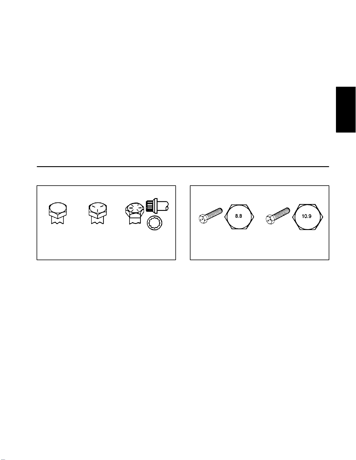
Fastener Identification
As noted in the following tables, torque values should be
reduced by 25% for lubricated fasteners to achieve
the similar stress as a dry fastener. Torque values may
also have to be reduced when the fastener is threaded
into aluminum or brass. The specific torque value
should be determined based on the aluminum or brass
material strength, fastener size, length of thread en
gagement, etc.
The standard method of verifying torque shall be performed by marking a line on the fastener (head or nut)
and mating part, then back off fastener 1/4 of a turn.
Measure the torque required to tighten the fastener until
the lines match up.
-
Product Records
and Maintenance
Grade 1 Grade 5 Grade 8
Inch Series Bolts and Screws
Figure 1 Figure 2
Class 8.8 Class 10.9
Metric Bolts and Screws
Line Painter 1200 Page 2 – 3 Product Records and Maintenance
Page 12
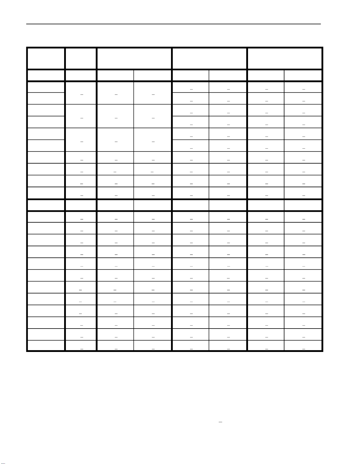
Standard Torque for Dry, Zinc Plated and Steel Fasteners (Inch Series)
Grade 1, 5 & SAE Grade 1 Bolts, Screws, Studs & SAE Grade 5 Bolts, Screws, Studs & SAE Grade 8 Bolts, Screws, Studs &
Thread Size
8 with Thin Sems** with Regular Height Nuts Sems** with Regular Height Nuts Sems** with Regular Height Nuts
Height Nuts (SAE J995 Grade 2 or Stronger Nuts) (SAE J995 Grade 2 or Stronger Nuts) (SAE J995 Grade 5 or Stronger Nuts)
in–lb in–lb N–cm in–lb N–cm in–lb N–cm
# 6 – 32 UNC 15 + 2 169 + 23 23 + 3 262 + 34
# 6 – 40 UNF
# 8 – 32 UNC 29 + 3 328 + 34 41 + 5 463 + 56
# 8 – 36 UNF
# 10 – 24 UNC 42 + 5 475 + 56 60 + 6 678 + 68
# 10 – 32 UNF
1/4 – 20 UNC 48 + 7 53 + 7 599 + 79 100 + 10 1130 + 113 140 + 15 1582 + 169
1/4 – 28 UNF 53 + 7 65 + 10 734 + 113 115 + 12 1299 + 136 160 + 17 1808 + 192
5/16 – 18 UNC 115 + 15 105 + 15 1186 + 169 200 + 25 2260 + 282 300 + 30 3390 + 339
5/16 – 24 UNF 138 + 17 128 + 17 1446 + 192 225 + 25 2542 + 282 325 + 33 3672 + 373
3/8 – 16 UNC 16 + 2 16 + 2 22 + 3 30 + 3 41 + 4 43 + 5 58 + 7
3/8 – 24 UNF 17 + 2 18 + 2 24 + 3 35 + 4 47 + 5 50 + 6 68 + 8
7/16 – 14 UNC 27 + 3 27 + 3 37 + 4 50 + 5 68 + 7 70 + 7 95 + 9
7/16 – 20 UNF 29 + 3 29 + 3 39 + 4 55 + 6 75 + 8 77 + 8 104 + 11
10 + 2
13 + 2
18 + 2
ft–lb ft–lb N–m ft–lb N–m ft–lb N–m
13 + 2
25 + 5
30 + 5
147 + 23
17 + 2 192 + 23 25 + 3 282 + 34
282 + 56
31 + 4 350 + 45 43 + 5 486 + 56
339 + 56
48 + 5 542 + 56 68 + 7 768 + 79
1/2 – 13 UNC 30 + 3 48 + 7 65 + 9 75 + 8 102 + 11 105 + 11 142 + 15
1/2 – 20 UNF 32 + 4 53 + 7 72 + 9 85 + 9 115 + 12 120 + 12 163 + 16
5/8 – 11 UNC 65 + 10 88 + 12 119 + 16 150 + 15 203 + 20 210 + 21 285 + 28
5/8 – 18 UNF 75 + 10 95 + 15 129 + 20 170 + 18 230 + 24 240 + 24 325 + 33
3/4 – 10 UNC 93 + 12 140 + 20 190 + 27 265 + 27 359 + 37 375 + 38 508 + 52
3/4 – 16 UNF 115 + 15 165 + 25 224 + 34 300 + 30 407 + 41 420 + 43 569 + 58
7/8 – 9 UNC 140 + 20 225 + 25 305 + 34 430 + 45 583 + 61 600 + 60 813 + 81
7/8 – 14 UNF 155 + 25 260 + 30 353 + 41 475 + 48 644 + 65 667 + 66 904 + 89
** A Sems screw is a self–tapping screw equipped with
a captive washer.
NOTE: Reduce torque values listed in the table above
by 25% for lubricated fasteners. Lubricated fasteners
are defined as threads coated with a lubricant such as
NOTE: Torque values may have to be reduced when
engine oil or thread sealant such as Loctite.
installing fasteners into threaded aluminum or brass.
The specific torque value should be determined based
on the fastener size, the aluminum or base material
strength, length of thread engagement, etc.
NOTE: The nominal torque values listed above for
Grade 5 and 8 fasteners are based on 75% of the mini
mum proof load specified in SAE J429. The tolerance is
approximately +
10% of the nominal torque value. Thin
height nuts include jam nuts.
-
Product Records and Maintenance
Page 2 – 4
Line Painter 1200
Page 13
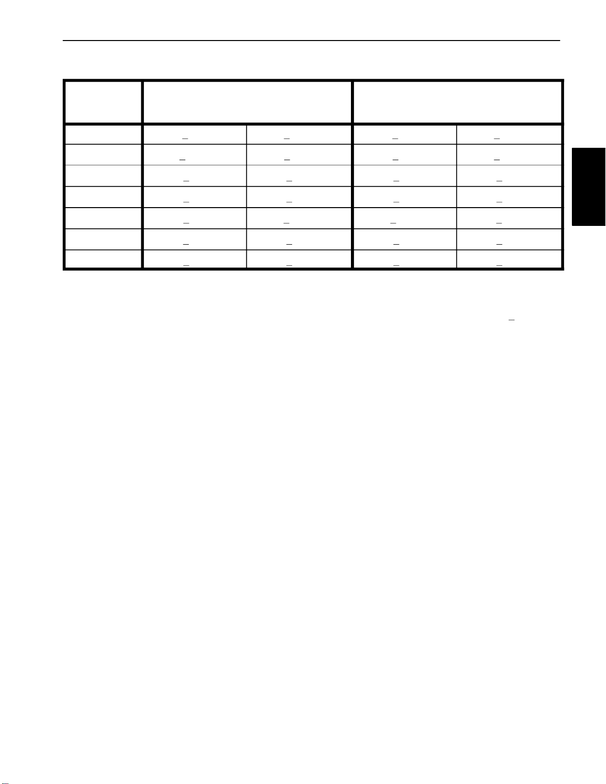
Standard Torque for Dry, Zinc Plated and Steel Fasteners (Metric Fasteners)
Class 8.8 Bolts, Screws and Studs with
Thread Size
M5 X 0.8 57 + 6 in–lb 644 + 68 N–cm 78 + 8 in–lb 881 + 90 N–cm
M6 X 1.0 96 + 10 in–lb 1085 + 113 N–cm 133 + 14 in–lb 1503 + 158 N–cm
M8 X 1.25 19 + 2 ft–lb 26 + 3 N–m 28 + 3 ft–lb 38 + 4 N–m
M10 X 1.5 38 + 4 ft–lb 52 + 5 N–m 54 + 6 ft–lb 73 + 8 N–m
M12 X 1.75 66 + 7 ft–lb 90 + 10 N–m 93 + 10 ft–lb 126 + 14 N–m
M16 X 2.0 166 + 17 ft–lb 225 + 23 N–m 229 + 23 ft–lb 310 + 31 N–m
M20 X 2.5 325 + 33 ft–lb 440 + 45 N–m 450 + 46 ft–lb 610 + 62 N–m
NOTE: Torque values may have to be reduced when
installing fasteners into threaded aluminum or brass.
The specific torque value should be determined based
on the fastener size, the aluminum or base material
strength, length of thread engagement, etc.
NOTE: Reduce torque values listed in the table above
by 25% for lubricated fasteners. Lubricated fasteners
are defined as threads coated with a lubricant such as
engine oil or thread sealant such as Loctite.
Regular Height Nuts
(Class 8 or Stronger Nuts)
NOTE: The nominal torque values listed above are
based on 75% of the minimum proof load specified in
SAE J1199. The tolerance is approximately +
nominal torque value.
Class 10.9 Bolts, Screws and Studs with
Regular Height Nuts
(Class 10 or Stronger Nuts)
10% of the
Product Records
and Maintenance
Line Painter 1200 Page 2 – 5 Product Records and Maintenance
Page 14
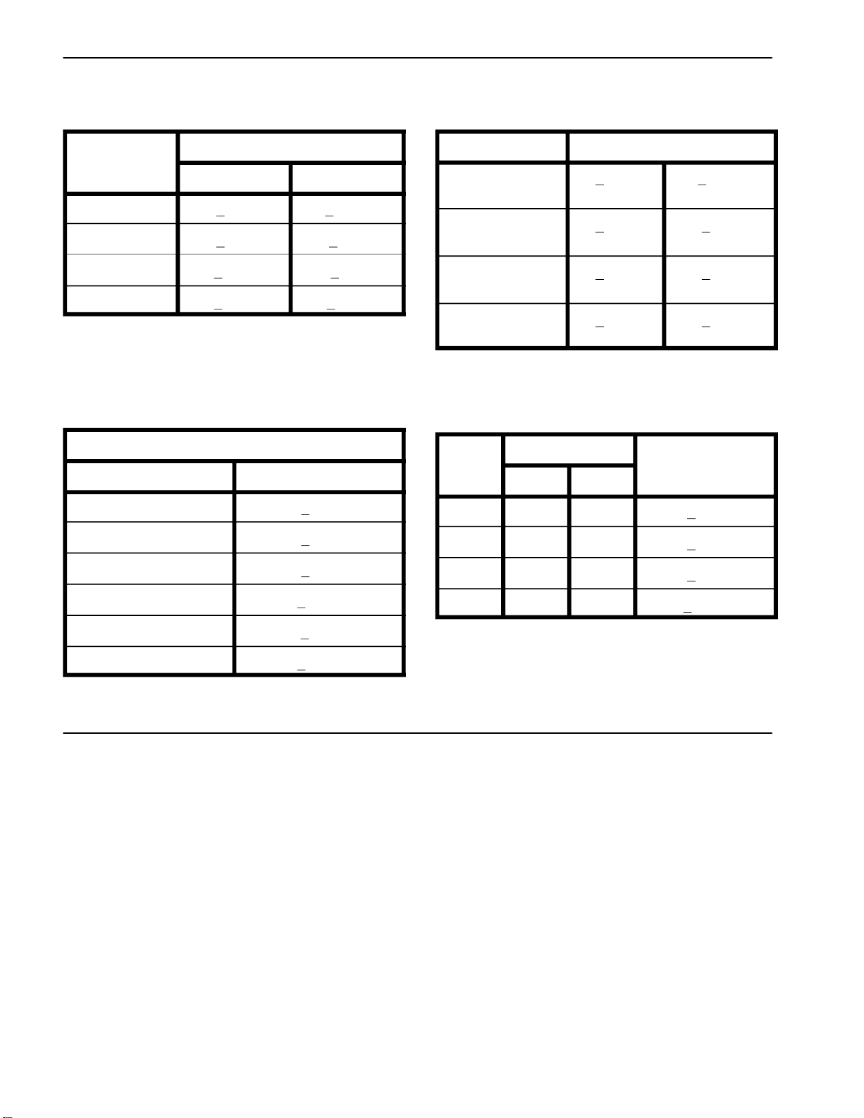
Other Torque Specifications
SAE Grade 8 Steel Set Screws Wheel Bolts and Lug Nuts
Recommended Torque
Thread Size
Square Head Hex Socket
1/4 – 20 UNC 140 + 20 in–lb 73 + 12 in–lb
5/16 – 18 UNC 215 + 35 in–lb 145 + 20 in–lb
3/8 – 16 UNC 35 + 10 ft–lb 18 + 3 ft–lb
1/2 – 13 UNC 75 + 15 ft–lb 50 + 10 ft–lb
Thread Cutting Screws
(Zinc Plated Steel)
Type 1, Type 23 or Type F
Thread Size Baseline Torque*
No. 6 – 32 UNC 20 + 5 in–lb
No. 8 – 32 UNC 30 + 5 in–lb
Thread Size
7/16 – 20 UNF
Grade 5
1/2 – 20 UNF
Grade 5
M12 X 1.25
Class 8.8
M12 X 1.5
Class 8.8
** For steel wheels and non–lubricated fasteners.
Thread Cutting Screws
(Zinc Plated Steel)
Thread
Size
No. 6 18 20 20 + 5 in–lb
No. 8 15 18 30 + 5 in–lb
Threads per Inch
Type A Type B
Recommended Torque**
65 + 10 ft–lb 88 + 14 N–m
80 + 10 ft–lb 108 + 14 N–m
80 + 10 ft–lb 108 + 14 N–m
80 + 10 ft–lb 108 + 14 N–m
orque* Baseline Torque*
No. 10 – 24 UNC 38 + 7 in–lb
1/4 – 20 UNC 85 + 15 in–lb
5/16 – 18 UNC 110 + 20 in–lb
3/8 – 16 UNC 200 + 100 in–lb
Conversion Factors
in–lb X 11.2985 = N–cm N–cm X 0.08851 = in–lb
ft–lb X 1.3558 = N–m N–m X 0.7376 = ft–lb
No. 10 12 16 38 + 7 in–lb
No. 12 11 14 85 + 15 in–lb
* Hole size, material strength, material thickness & finish
must be considered when determining specific torque
values. All torque values are based on non–lubricated
fasteners.
Product Records and Maintenance
Page 2 – 6
Line Painter 1200
Page 15

Table of Contents
INTRODUCTION . . . . . . . . . . . . . . . . . . . . . . . . . . . . . . 2
SPECIFICATIONS . . . . . . . . . . . . . . . . . . . . . . . . . . . . 3
GENERAL INFORMATION . . . . . . . . . . . . . . . . . . . . . 4
Fuel Shut–off Valve . . . . . . . . . . . . . . . . . . . . . . . . . . 4
SERVICE AND REPAIRS . . . . . . . . . . . . . . . . . . . . . . 5
Cooling System . . . . . . . . . . . . . . . . . . . . . . . . . . . . . 5
Fuel Tank . . . . . . . . . . . . . . . . . . . . . . . . . . . . . . . . . . 6
Engine . . . . . . . . . . . . . . . . . . . . . . . . . . . . . . . . . . . . . 8
KAWASAKI FJ180V SERVICE MANUAL
Chapter 3
Gasoline Engine
Engine
Gasoline
Line Painter 1200 Page 3 – 1 Gasoline Engine
Page 16

Introduction
This Chapter gives information about specifications,
maintenance, troubleshooting, testing and repair of the
Kawasaki FJ180V gasoline engine used in the Line
Painter 1200.
Most repairs and adjustments require tools which are
commonly available in many service shops. Special
tools are described in the Kawasaki FJ180V Service
Manual that is included at the end of this Chapter. The
use of some specialized test equipment is explained.
However, the cost of the test equipment and the special
ized nature of some repairs may dictate that the work be
done at an engine repair facility.
-
Service and repair parts for the Kawasaki engine used
to power the Line Painter 1200 are supplied through
your local Toro distributor. Be prepared to provide your
distributor with the Toro model and serial number.
Gasoline Engine Page 3 – 2 Line Painter 1200
Page 17

Specifications
Item Description
Make / Designation Kawasaki, FJ180V, 4–stroke,
air–cooled, OHV, single cylinder
Bore x Stroke 2.6” x 2.1” (65 mm x 54 mm)
Total Displacement 10.9 cu. in. (179 cc)
Compression Ratio 8.5:1
Carburetor Float Feed, Fixed Main Jet
Governor Mechanical
High Idle (No Load) 2800 + 100 RPM
Direction of Rotation Counter Clockwise (Facing PTO Shaft)
Fuel Unleaded, Automotive Grade Gasoline
Fuel Tank Capacity 4 Quart (3.8 Liter)
Engine Oil See Operator’s Manual
Lubrication System Pressure Lubrication
Oil Capacity (Including Oil Filter) 0.9 Quart (0.85 Liter)
Engine
Gasoline
Air Cleaner Dual Element
Ignition System Flywheel Magneto CDI
Spark Plug NGK BPR5ES
Spark Plug Gap .028” to .032” (.7 to .8 mm)
Dry Weight 35.3 Pounds (16 Kilograms)
Line Painter 1200 Page 3 – 3 Gasoline Engine
Page 18
General Information
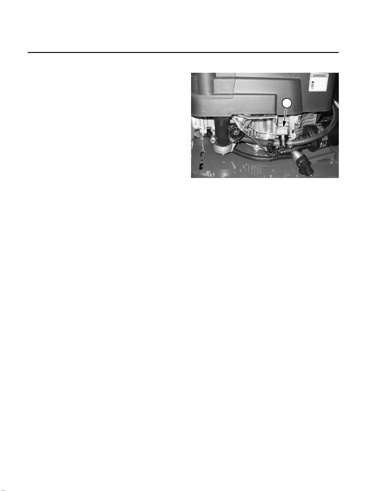
Fuel Shut–off Valve
The fuel shut off valve is positioned in the fuel hose between the fuel tank and the carburetor inlet. It has two
positions: CLOSED and OPEN. Turn valve to the closed
position when storing or transporting the machine. Ro
tate valve to the open position before starting the engine.
-
1
Figure 1
1. Fuel shut–off valve
Gasoline Engine Page 3 – 4 Line Painter 1200
Page 19
Service and Repairs
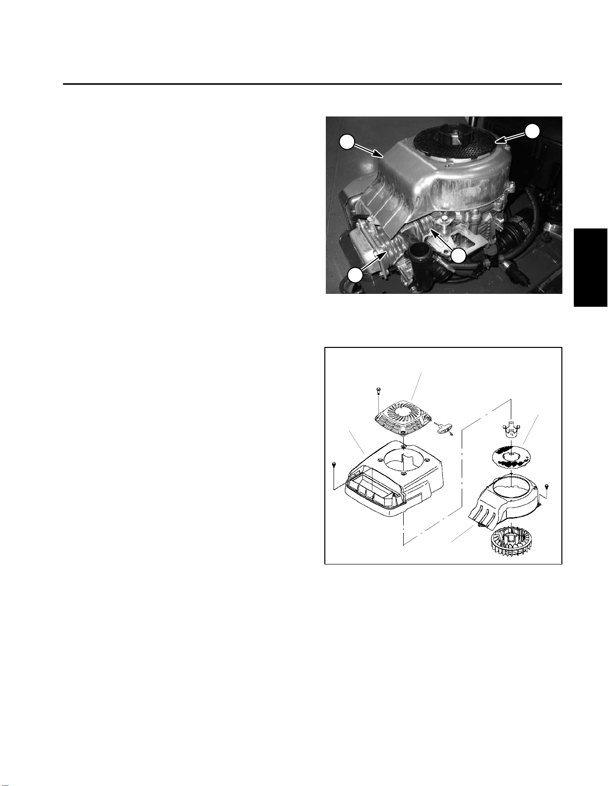
Cooling System
IMPORTANT: The engine that powers the Line
Painter 1200 is air–cooled. Operating the engine
with dirty or plugged cooling fins or a plugged or
dirty blower housing will result in engine overheat
ing and damage.
1. Park machine on a level surface, stop engine, engage parking brake and remove key from the ignition
switch. Remove high tension lead from the spark plug
and position the lead away from the spark plug.
-
1
2
IMPORTANT: Never clean engine with pressurized
water. Water could enter and contaminate the fuel
system.
2. Remove rewind starter and clean rotating screen
(Fig.2).
3. If necessary, remove engine cover, rotating screen
and blower housing from engine (Fig. 3). Clean blower
housing and engine cooling fins of dirt and debris.
IMPORTANT: Never operate engine without the
blower housing installed. Overheating and engine
damage will result.
4. Make sure blower housing, rotating screen and engine cover are reinstalled to the engine if removed.
5. Attach high tension lead to the spark plug.
3
3
Figure 2
1. Rotating screen 3. Cooling fins
2. Blower housing
1
2
Engine
Gasoline
3
4
Figure 3
1. Rewind starter 3. Rotating screen
2. Engine cover 4. Blower housing
Line Painter 1200 Page 3 – 5 Gasoline Engine
Page 20
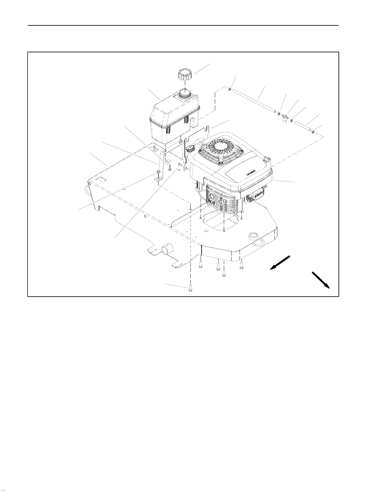
Fuel Tank
10
11
12
13
2
3
1
4
3
5
3
6
14
3
7
1. Fuel tank
2. Fuel tank cap
3. Hose clamp (4 used)
4. Fuel hose
5. Fuel shut off valve
9
RIGHT
FRONT
8
Figure 4
6. Fuel hose
7. Engine
8. Screw (2 used)
9. Washer head screw (2 used)
10. Nut (2 used)
11. Frame
12. Fuel tank support
13. Washer head screw (2 used)
14. Fuel tank bracket
Line Painter 1200Gasoline Engine Page 3 – 6
Page 21
DANGER
Because gasoline is highly flammable, use caution when storing or handling it. Do not smoke
while filling the fuel tank. Do not fill fuel tank
while engine is running, hot, or when machine is
in an enclosed area. Always fill fuel tank outside
and wipe up any spilled fuel before starting the
engine. Store fuel in a clean, safety–approved
container and keep cap in place. Use gasoline for
the engine only; not for any other purpose.
Check Fuel Lines and Connections
Check fuel lines and connections periodically as recommended in the Operator’s Manual. Check lines for deterioration, damage, leaking or loose connections.
Replace hoses, clamps and connections as necessary.
Drain and Clean Fuel Tank
3. Remove high tension lead from the spark plug and
position the lead away from the spark plug.
4. Close fuel shut off valve. Disconnect fuel hose from
carburetor inlet.
5. Place disconnected hose in appropriate container
and open fuel shut off valve to allow fuel tank to drain
completely.
6. Remove fuel tank using Figure 4 as a guide. If fuel
tank bracket (item 14) removal is necessary, remove
ground wire from bracket.
7. If fuel in tank was contaminated, remove and clean
carburetor (see Kawasaki FJ180V Service Manual at
the end of this chapter).
Fuel Tank Installation (Fig. 4)
1. If carburetor was removed from engine for cleaning,
install carburetor (see Kawasaki FJ180V Service Manu
al at the end of this chapter).
-
Engine
Gasoline
IMPORTANT: If fuel tank is to be drained, drain fuel
outdoors.
Drain and clean the fuel tank periodically as recommended in the Operator’s Manual. Also, drain and clean
the fuel tank if the fuel system becomes contaminated
or if the machine is to be stored for an extended period.
NOTE: The fuel tank is equipped with an integral filter
screen at the tank outlet.
To clean fuel tank, flush tank and fuel hoses out with
clean solvent. Make sure tank is free of contaminates
and debris.
Fuel Tank Removal (Fig. 4)
1. Park machine on a level surface, stop engine, engage parking brake and remove key from the ignition
switch. Remove high tension lead from the spark plug
and position the lead away from the spark plug.
2. Allow engine to cool before removing fuel tank.
2. Install fuel tank to frame using Figure 4 as a guide.
If ground wire was removed from fuel tank bracket (item
14) secure ground wire to bracket with screw.
3. Connect fuel hose to carburetor inlet. Make sure that
fuel hoses are secured with hose clamps.
4. Attach high tension lead to the spark plug.
5. Fill fuel tank (see Operator’s Manual).
Line Painter 1200 Page 3 – 7 Gasoline Engine
Page 22
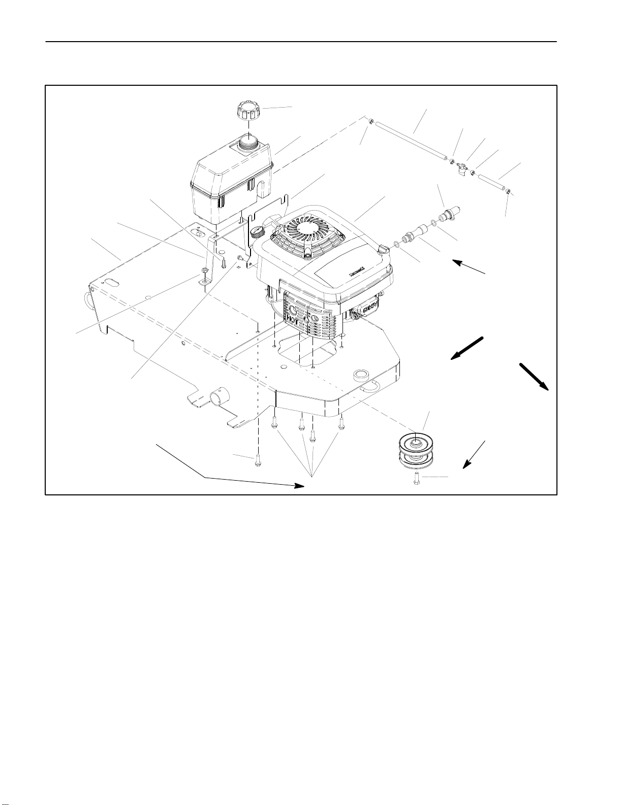
Engine
11
15
14
12
16
14
14
17
13
2
10
9
8
1
14
3
4
3
7
20 to 30 ft–lb
(27 to 41 N–m)
RIGHT
FRONT
6
250 to 450 in–lb
(28 to 51 N–m)
5
1. Engine
2. Oil drain valve
3. O–ring
4. Drain extension
5. Screw (6 used)
6. Washer head screw (2 used)
7. Nut (2 used)
8. Frame
9. Fuel tank support
10. Washer head screw (2 used)
11. Fuel tank cap
12. Fuel tank
13. Fuel tank bracket
Removal (Fig. 5)
1. Park machine on a level surface, stop engine, engage parking brake and remove key from the ignition
switch. Remove high tension lead from the spark plug
and position the lead away from the spark plug.
2. If engine is to be disassembled, it may be easier to
drain oil from engine before removing engine from machine (see Operator’s Manual).
18
50 to 60 ft–lb
(68 to 81 N–m)
Loctite #242
19
5
Figure 5
14. Hose clamp (4 used)
15. Fuel hose
16. Fuel shut off valve
17. Fuel hose
18. Engine pulley
19. Cap screw
4. Remove fuel tank from machine (see Fuel Tank Removal in this section).
5. If machine is equipped with a hour meter, remove
hour meter pickup wire from spark plug lead on engine.
Position pickup wire away from engine.
6. Disconnect stop switch wire from engine (Fig. 6).
Make sure that ground wire is removed from fuel tank
bracket (item 14).
3. Close fuel shut off valve. Disconnect fuel hose from
carburetor inlet.
Line Painter 1200Gasoline Engine Page 3 – 8
Page 23
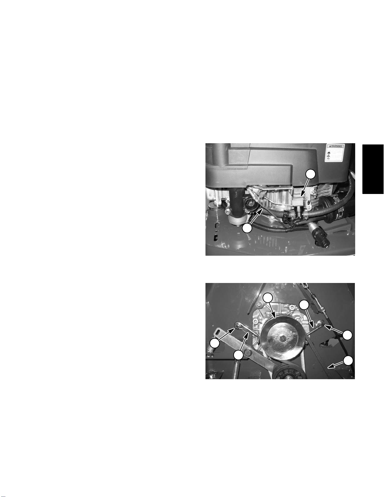
7. On the underside of the machine frame (Fig. 7):
A. Loosen flange nuts that retain two (2) belt guides
to frame. Position belt guides away from engine
pulley.
8. Install fuel tank to machine (see Fuel Tank Installation in this section).
9. If machine is equipped with a hour meter, install hour
meter pickup wire to spark plug lead on engine.
B. Loosen idler tension on pump drive belt (lower)
and transmission drive bolt (upper) and remove belts
from engine pulley.
C. Remove four (4) screws that secure engine to
machine.
8. Lift the engine from the frame.
9. If necessary, remove cap screw that secures pulley
to engine crankshaft. Slide pulley from crankshaft.
Installation (Fig. 5)
1. Position machine on a level surface.
2. Make sure that all parts removed from the engine
during maintenance or rebuilding are properly installed
to the engine.
3. If pulley was removed from engine, apply antisieze
lubricant to engine crankshaft. Slide pulley onto crank
shaft making sure to align pulley key with crankshaft
slot.
4. Apply Loctite #242 (or equivalent) to threads of cap
screw (item 19). Secure pulley to crankshaft with cap
screw. Torque cap screw from 50 to 60 ft–lb (68 to 81
N–m).
10.Connect stop switch wire to engine. Secure ground
wire to fuel tank bracket (item 14) with screw.
11. Check and adjust engine oil level as needed (See
Checking Engine Oil Level).
12.Attach high tension lead to the spark plug.
13.Make sure that fuel hose is secured to carburetor inlet. Open fuel shut–off valve.
1
-
2
Figure 6
1. Fuel shut off valve 2. Stop switch wire
Engine
Gasoline
5. Position engine on the frame.
6. Align holes in frame with engine mounting holes. Secure engine to frame with four (4) screws. Torque
screws from 250 to 450 in–lb (28 to 51 N–m).
7. On the underside of the machine frame (Fig. 7):
A. Install transmission drive belt (upper) and pump
drive belt (lower) onto engine pulley. Make sure that
belts are correctly routed at idler pulleys.
B. Position two (2) belt guides to allow from .060” to
.130” (1.5 to 3.3 mm) clearance when the traction
(upper) belt is tensioned by the idler pulley. When
properly positioned, tighten flange nuts to secure
belt guides to frame.
4
2
1
1
2
3
Figure 7
1. Flange nut 3. Pump drive belt
2. Belt guide 4. Engine pulley
Line Painter 1200 Page 3 – 9 Gasoline Engine
Page 24

This page is intentionally blank.
Gasoline Engine Page 3 – 10 Line Painter 1200
Page 25

Table of Contents
ELECTRICAL SCHEMATIC . . . . . . . . . . . . . . . . . . . . 2
SPECIAL TOOLS . . . . . . . . . . . . . . . . . . . . . . . . . . . . . 3
TROUBLESHOOTING . . . . . . . . . . . . . . . . . . . . . . . . . 4
COMPONENT TESTING . . . . . . . . . . . . . . . . . . . . . . . 5
On/Off Switch . . . . . . . . . . . . . . . . . . . . . . . . . . . . . . . 5
Hourmeter (Optional) . . . . . . . . . . . . . . . . . . . . . . . . 6
Chapter 4
Electrical System
System
Electrical
Line Painter 1200 Page 4 – 1 Electrical System
Page 26

Electrical Schematic
HIGH TENSION LEAD
BLACK
BLACK
IGNITION COIL
ENGINE
MAGNETO
(FLYWHEEL)
HOUR METER
(OPTIONAL)
BROWN
ON\OFF SWITCH
is open in the ON
position.
ON/OFF SWITCH
BLACK
Electrical System
Page 4 – 2
Line Painter 1200
Page 27
Special Tools
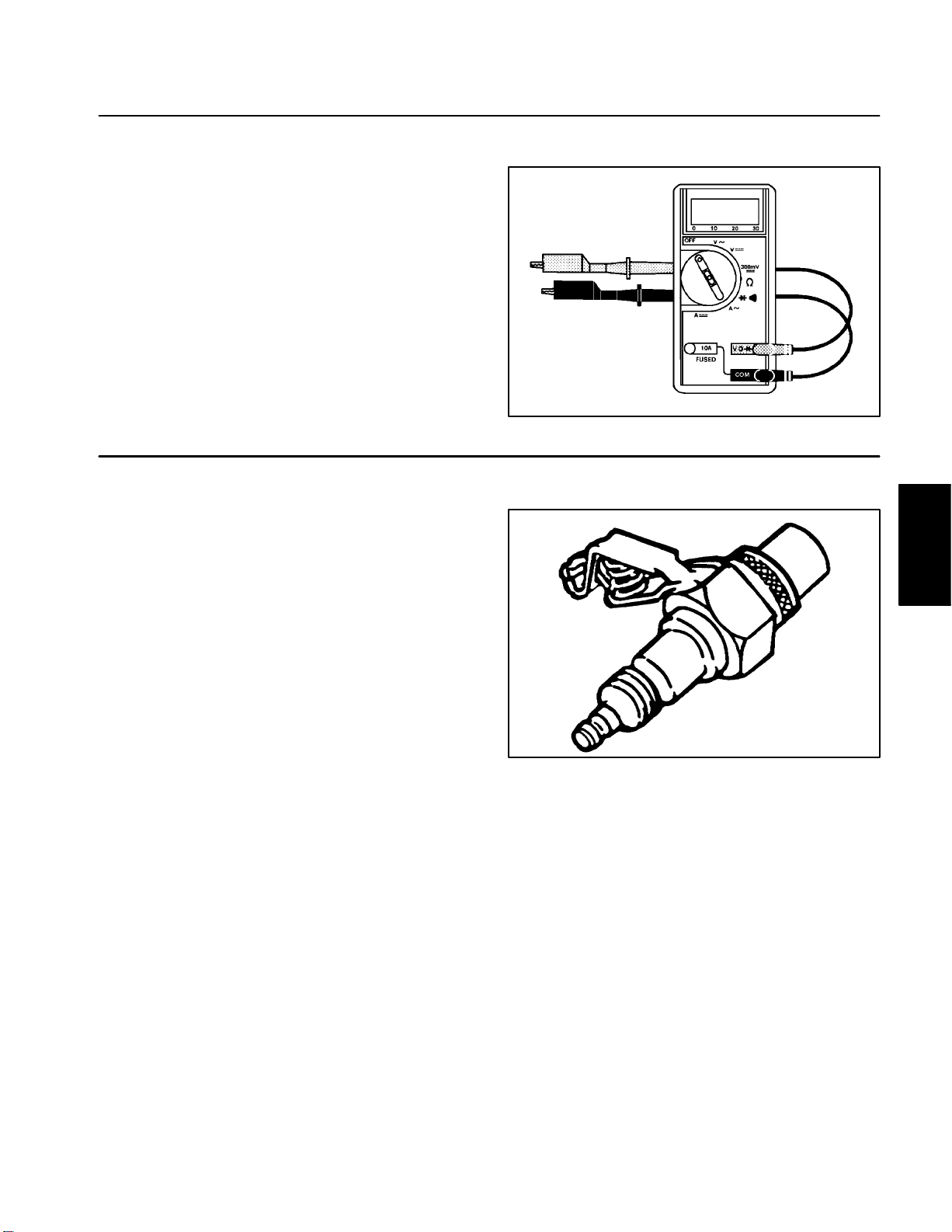
Multimeter
The multimeter can test electrical components and circuits for current (amps), resistance (ohms) or voltage.
NOTE: Toro recommends the use of a DIGITAL Volt–
Ohm–Amp multimeter when testing electrical circuits.
The high impedance (internal resistance) of a digital me
ter in the voltage mode will make sure that excess current is not allowed through the meter. This excess
current can cause damage to circuits not designed to
carry it.
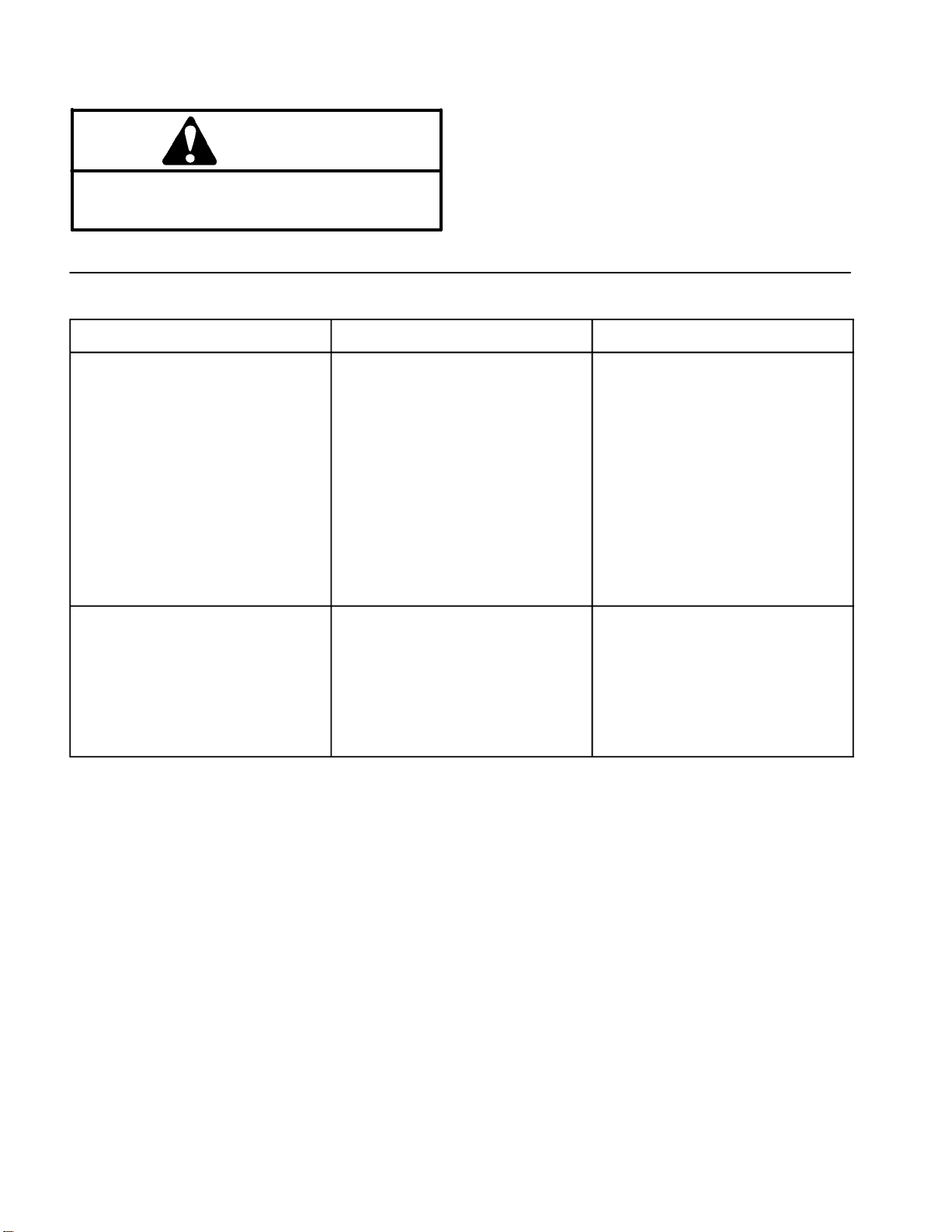
Spark Tester – TOR4036
The spark tester can test magneto ignitions. The spark
tester determines if ignition is present.
-
Figure 1
Figure 2
System
Electrical
Line Painter 1200 Page 4 – 3 Electrical System
Page 28
Troubleshooting
For effective troubleshooting and repairs, there must be
CAUTION
Remove all jewelry, especially rings and
watches, before doing any electrical
troubleshooting or testing.
Starting Problems
Problem Possible Causes Correction
a good understanding of the electrical circuits and com
ponents used on this machine (see Electrical Schematic
in this chapter).
NOTE: See the Kawasaki FJ180V Service Manual at
the end of Chapter 3 – Engine for troubleshooting of en
gine electrical problems.
-
-
Engine will not start. ON/OFF switch is in the OFF
position.
ON/OFF switch is faulty. Replace ON/OFF switch.
Ignition spark plug lead is not
connected to spark plug.
Electrical wires are loose or Check electrical connections.
damaged. Repair wiring.
Engine is malfunctioning. See Kawasaki FJ180V Service
Engine will start, but will not
continue to run.
Electrical wires are loose or
damaged.
ON/OFF switch is faulty. Replace ON/OFF switch.
Engine is malfunctioning. See Kawasaki FJ180V Service
Turn switch to ON.
Connect high tension lead to spark
plug.
Manual at the end of Chapter 3 –
Engine.
Check electrical connections.
Repair wiring.
Manual at the end of Chapter 3 –
Engine.
Electrical System
Page 4 – 4
Line Painter 1200
Page 29

Component Testing
For accurate resistance and/or continuity checks, electrically disconnect the component being tested from the
circuit (e.g. unplug the ignition switch connector before
doing a continuity check).
On/Off Switch
The on/off switch is used to shut the engine off. When
the on/off switch is in the off position, the engine arma
ture is grounded to prevent the engine from running.
This switch is located handle panel (Fig. 3).
Testing
In the OFF position, there should be continuity between
the two switch terminals. In the RUN position, there
should not be continuity between the two switch termi
nals.
-
-
1
Figure 3
1. On/Off switch
System
Electrical
Figure 4
Line Painter 1200 Page 4 – 5 Electrical System
Page 30

Hourmeter (Optional)
The optional hourmeter available for the Line Painter
1200 uses an inductive pickup wire connected to the
spark plug wire to sense when the engine is running.
The hourmeter should increase 1/10 of an hour every six
(6) minutes of engine running time.
The hourmeter uses its own internal battery for operation. The hourmeter battery is not replaceable.
NOTE: The hourmeter display is programmed to flash
service reminders initially at 50 hours and then every
100 hours thereafter. The display will flash for three
hours before and three hours after these running times.
Regardless of these service reminders, follow the main
tenance intervals identified in the Line Painter 1200 Operator’s Manual.
-
Figure 5
Electrical System
Page 4 – 6
Line Painter 1200
Page 31

Table of Contents
Chapter 5
Paint System
SPECIFICATIONS . . . . . . . . . . . . . . . . . . . . . . . . . . . . 2
PAINT SCHEMATIC . . . . . . . . . . . . . . . . . . . . . . . . . . . 3
CIRCUIT OPERATION . . . . . . . . . . . . . . . . . . . . . . . . . 4
Paint Circuit . . . . . . . . . . . . . . . . . . . . . . . . . . . . . . . . 4
Flush Circuit . . . . . . . . . . . . . . . . . . . . . . . . . . . . . . . . 6
TROUBLESHOOTING . . . . . . . . . . . . . . . . . . . . . . . . . 8
GENERAL INFORMATION . . . . . . . . . . . . . . . . . . . . . 9
Paint/Flush Lever . . . . . . . . . . . . . . . . . . . . . . . . . . . 9
Quick Disconnect Fittings . . . . . . . . . . . . . . . . . . . . 9
Thread Sealant for Paint System Fittings . . . . . . . 9
ADJUSTMENTS 10. . . . . . . . . . . . . . . . . . . . . . . . . . . . .
Spray Pump Relief Valve Adjustment 10. . . . . . . . .
SERVICE AND REPAIRS . . . . . . . . . . . . . . . . . . . . . 12
Paint Tank . . . . . . . . . . . . . . . . . . . . . . . . . . . . . . . . 12
Tank Support . . . . . . . . . . . . . . . . . . . . . . . . . . . . . . 14
Flush (Water) Tank . . . . . . . . . . . . . . . . . . . . . . . . . 16
Check Valve Service . . . . . . . . . . . . . . . . . . . . . . . . 18
Paint Shutoff Valve . . . . . . . . . . . . . . . . . . . . . . . . . 20
Pressure Regulator . . . . . . . . . . . . . . . . . . . . . . . . . 22
Ball Valve . . . . . . . . . . . . . . . . . . . . . . . . . . . . . . . . . 24
Spray Pump Drive Belt . . . . . . . . . . . . . . . . . . . . . . 26
Spray Pump . . . . . . . . . . . . . . . . . . . . . . . . . . . . . . . 28
Spray Pump Service . . . . . . . . . . . . . . . . . . . . . . . . 30
Spray Head . . . . . . . . . . . . . . . . . . . . . . . . . . . . . . . 32
Paint
System
Line Painter 1200 Page 5 – 1 Paint System
Page 32

Specifications
Item Description
Pump Diaphragm Pump with 5 Chambers
Pump Capacity 4 GPM (15.1 LPM)
Relief Pressure 65 PSI (4.5 Bar)
Paint Tank Capacity 12 Gallons (45.4 Liters)
Water (Flush) Tank Capacity 2.5 Gallons (9.5 Liters)
Paint System Page 5 – 2 Line Painter 1200
Page 33

Paint Schematic
(OFF)
(OFF)
(OFF POSITION)
Line Painter 1200
Hydraulic Schematic
Paint
System
Line Painter 1200 Page 5 – 3 Paint System
Page 34

Circuit Operation
(OFF)
(OFF)
Line Painter 1200
Paint Circuit
Working Pressure
Return (Agitation)
Suction
Flow
Paint System Page 5 – 4 Line Painter 1200
Page 35

Paint Circuit
The Line Painter 1200 paint circuit uses a positive displacement diaphragm pump to move paint from the
paint tank to the spray nozzle. The spray pump is a self–
priming diaphragm pump that has a dry crankcase.
The engine drives the spray pump indirectly through pulleys and a V–belt. The spray pump belt is always tensioned by a backside idler pulley so the pump is being
rotated whenever the engine is running.
When the pump is rotated, the downward stroke of the
pump’s diaphragm creates suction to allow fluid (paint)
to be drawn from the paint tank to the pump via hoses,
a ball valve (in the paint position) and a 40 mesh screen
filter. Pump design prevents fluid from being pumped
back into the suction line.
Once to the pump, the fluid (paint) is pushed by the upward stroke of the pump’s diaphragm to the pressure
side of the spray system through hoses, control valves
and the spray nozzle. Pump design prevents fluid from
being drawn back into the pump. Maximum pressure in
the system is limited by an adjustable relief valve located
in the pump.
An adjustable pressure regulator is used by the operator
to set paint circuit pressure on the Line Painter 1200.
Flow in excess of the regulator setting is directed back
to the paint tank via a ball valve (in the paint position).
This return flow is used for paint tank agitation. An op
tional pressure gauge (if equipped) indicates system
pressure.
A mechanically actuated spool valve is used to turn the
spray nozzle on/off. Spool valve shift occurs when the
operator depresses or releases the paint control lever.
-
Paint
System
Line Painter 1200 Page 5 – 5 Paint System
Page 36

(OPEN)
Line Painter 1200
Flush Circuit
Working Pressure
Return
Suction
Flow
Paint System Page 5 – 6 Line Painter 1200
Page 37

Flush Circuit
The Line Painter 1200 paint circuit uses a positive displacement diaphragm pump to move fluid (water) from
the flush (water) tank through the spray system. The
spray pump is a self–priming diaphragm pump that has
a dry crankcase.
When the pump is rotated, the downward stroke of the
pump’s diaphragm creates suction to allow fluid (water)
to be drawn from the flush tank to the pump via hoses,
a one–way check valve, a ball valve (in the flush posi
tion) and a 40 mesh screen filter.
Once to the pump, the fluid (water) is pushed by the upward stroke of the pump’s diaphragm to the pressure
side of the spray system through hoses, control valves
and the spray nozzle. Maximum pressure in the system
is limited by an adjustable relief valve located in the dia
phragm pump.
Flow in excess of the adjustable pressure regulator setting is directed back to the flush (water) suction line via
a ball valve (in the flush position).
Flow through the flush circuit is used to dilute and remove paint from the ball valves, screen filter, spray
pump, regulator, spool valve, spray nozzle and all
hoses.
A one–way check valve is positioned between the flush
(water) tank and the ball valve (see schematic). This
check valve prevents paint from entering the flush (wa
ter) tank when the paint/flush lever is moved from the
paint position to the flush position and while the machine
is operated in the flush mode.
NOTE: If the flush system is not cleaned after use, diluted paint may cause check valve and associated
hoses to become blocked. If the check valve is stuck
open, paint may enter the flush (water) tank when the
paint/flush lever is moved from the paint position to the
flush position. If the check valve is stuck closed, the flush
system may not operate.
-
Paint
System
Line Painter 1200 Page 5 – 7 Paint System
Page 38

Troubleshooting
Á
Á
Á
Á
Á
Á
Á
Á
Á
Á
Á
Á
Á
Á
Á
Á
Á
Á
Á
Á
Á
Á
Á
Á
Á
Á
Á
Á
Á
Á
Á
Á
Á
Á
Á
Á
Á
Á
Á
Á
Á
Á
Á
Á
Á
Á
Á
Á
Á
Á
Á
Á
Á
Á
Á
Á
Á
Á
Á
Á
Á
Á
Á
Á
Á
Á
Á
Á
Á
Á
Problem
БББББББББББББББББББББББББББББББББББ
Spray system leaks fluid.
БББББББББББ
Á
БББББББББББ
Á
БББББББББББББББББББББББББББББББББББ
Spray pressure is low.
БББББББББББ
Á
БББББББББББ
Á
БББББББББББ
Á
БББББББББББ
Á
БББББББББББ
Á
БББББББББББ
Á
БББББББББББ
Á
БББББББББББ
Á
БББББББББББ
Á
БББББББББББ
Á
БББББББББББ
Á
БББББББББББ
Á
No spray output from nozzle.
БББББББББББББББББББББББББББББББББББ
БББББББББББ
Á
БББББББББББ
Á
БББББББББББ
Á
БББББББББББ
Á
БББББББББББ
Á
БББББББББББ
Á
БББББББББББ
Á
БББББББББББ
Á
БББББББББББ
Á
БББББББББББ
Á
БББББББББББ
Á
БББББББББББ
Á
БББББББББББ
Á
БББББББББББББББББББББББББББББББББББ
No spray output from nozzle in the
flush mode.
БББББББББББ
Á
БББББББББББ
Á
Nozzle leaks when paint valve is
БББББББББББББББББББББББББББББББББББ
closed.
БББББББББББ
Á
БББББББББББ
Á
БББББББББББ
Á
БББББББББББ
Á
БББББББББББ
Á
БББББББББББББББББББББББББББББББББББ
Paint is being pumped into the flush
БББББББББББ
Á
tank.
БББББББББББББББББББББББББББББББББББ
Paint System Page 5 – 8 Line Painter 1200
Possible Cause
Fitting(s) or hose(s) are loose or damaged.
ББББББББББББББББББББ
Á
O–ring(s) or seal(s) are missing or damaged.
ББББББББББББББББББББ
Á
Suction line is restricted.
ББББББББББББББББББББ
Á
Filter screen is plugged.
ББББББББББББББББББББ
Á
ББББББББББББББББББББ
Á
Pressure regulator is damaged or incorrectly adjusted.
ББББББББББББББББББББ
Á
Spray nozzle is worn or damaged.
ББББББББББББББББББББ
Á
Check valve in diaphragm nozzle is stuck or plugged.
ББББББББББББББББББББ
Á
ББББББББББББББББББББ
Á
Engine speed is low.
ББББББББББББББББББББ
Á
Pressure relief valve in spray pump is stuck.
ББББББББББББББББББББ
Á
ББББББББББББББББББББ
Á
Pump drive belt is slipping.
ББББББББББББББББББББ
Á
Spray pump is faulty.
ББББББББББББББББББББ
Á
Paint tank is empty.
ББББББББББББББББББББ
Á
Paint/Flush lever is in the off position.
ББББББББББББББББББББ
Á
Hose(s) are pinched or kinked.
ББББББББББББББББББББ
Á
ББББББББББББББББББББ
Á
Dried paint in system.
ББББББББББББББББББББ
Á
Filter screen is plugged.
ББББББББББББББББББББ
Á
ББББББББББББББББББББ
Á
Spray nozzle is clogged or damaged.
ББББББББББББББББББББ
Á
Check valve in diaphragm nozzle is stuck or plugged.
ББББББББББББББББББББ
Á
ББББББББББББББББББББ
Á
Paint shutoff valve is faulty.
ББББББББББББББББББББ
Á
Pump drive belt is slipping, damaged or broken.
ББББББББББББББББББББ
Á
Spray pump is faulty.
ББББББББББББББББББББ
Á
Flush tank is empty.
ББББББББББББББББББББ
Á
Check valve in flush tank outlet tube is stuck closed.
ББББББББББББББББББББ
Á
Check valve diaphragm in diaphragm nozzle body is leaking or
damaged.
ББББББББББББББББББББ
Á
ББББББББББББББББББББ
Á
Paint shutoff valve is not seating.
ББББББББББББББББББББ
Á
Paint control cable is not adjusted correctly (see Paint Control
ББББББББББББББББББББ
Á
Cable in the Service and Repairs section of Chapter 6 – Chassis
ББББББББББББББББББББ
Á
and Controls).
Check valve in flush tank outlet tube is stuck open.
ББББББББББББББББББББ
Á
Page 39

General Information
Paint/Flush Lever
To prevent paint system pressure spikes, the paint/flush
lever should normally be in either the paint mode or the
flush mode. It is recommended to use the OFF position
only when the engine is not running.
2
If the paint filter is to be cleaned and paint is in the paint
tank, turn the paint/flush lever to OFF (engine not run
ning) to prevent paint leakage.
Quick Disconnect Fittings
The Line Painter 1200 uses several quick disconnect fittings that provide excellent sealing and allow easy disassembly. To remove a hose from a quick disconnect
fitting, push the release collar in toward the fitting and
then pull the hose from the fitting. To install a hose into
a quick disconnect fitting, fully push the hose into the col
lar. Pull lightly on the hose to make sure it is secured in
the fitting.
If the end of the tubing is scratched, deformed or not cut
squarely, the fitting seal will not be effective and leakage
will occur.
-
3
Figure 1
1. Paint lever (in OFF) 3. Paint mode
2. Flush mode
2
1
-
3
1
Paint
System
Figure 2
1. Fitting 3. Hose
2. Release collar
Thread Sealant for Paint System Fittings
Many fittings used in the Line Painter 1200 paint system
have a sealant patch applied to the fitting threads. If a
fitting is being replaced and a sealant patch is evident on
the threads of the new fitting, there is no need to apply
additional thread sealant before installation.
If a fitting has been removed, however, the sealant patch
may not allow a leak–free seal if the fitting is re–installed.
If a fitting is to be re–installed, apply Saf–T–Lok brand
Line Painter 1200 Page 5 – 9 (Rev. A) Paint System
TPS (PTFE Sealant) to the fitting threads before
installation. If an alternate sealant is used, make sure
that it is compatible with nylon and polypropylene materials.
Page 40

Adjustments
Spray Pump Relief Valve Adjustment
The spray pump used on the Line Painter 1200 is
equipped with an adjustable relief valve (Fig. 3). Adjust
ment of the relief valve is made with a socket head screw
on the top of the pump. The end of the socket head
screw should be flush with the relief valve housing for
correct relief valve adjustment.
-
2
1
Figure 3
1. Spray pump 2. Socket head screw
Paint System Page 5 – 10 Line Painter 1200
Page 41

This page is intentionally blank.
Paint
System
Line Painter 1200 Page 5 – 11 Paint System
Page 42

Service and Repairs
Paint Tank
144 to 156 in–lb
(16.3 to 17.6 N–m)
192 to 216 in–lb
(21.7 to 24.4 N–m)
6
5
4
2
1
10
8
11
3
19
5
20
7
8
9
10
192 to 216 in–lb
(21.7 to 24.4 N–m)
14
13
12
15
16
17
18
RIGHT
FRONT
1. Paint tank
2. Nut
3. Tank support
4. Flat washer
5. Jam nut
6. Elbow fitting
7. Tank clamp (2 used)
8. Rubber washer
9. Outlet port
10. Ball valve
11. Recirculation port
12. O–ring
13. Drain valve
14. Elbow fitting
Removal (Fig. 4)
1. Park machine on a level surface, stop engine, engage parking brake and remove key from the ignition
switch. Remove high tension lead from the spark plug
and position the lead away from the spark plug.
2. Drain paint tank (see Operator’s Manual). Remove
tank lid and strainer.
Figure 4
15. Valve bracket
16. Flange head screw
17. Flange head screw (4 used)
18. Pump assembly
19. Flush tank
20. Slotted washer
3. Loosen nut that secures drain valve to tank (Fig. 5).
4. Remove two (2) flange head screws (item 16) that
secure drain valve to valve bracket. Remove nut from
drain valve and remove valve from machine. Retrieve
o–ring (item 12) from outside tank.
5. Remove agitation tube from elbow fitting (Fig. 5) (see
Quick Disconnect Fitting in the General Information section). Loosen and remove elbow fitting.
Line Painter 1200Page 5 – 12Paint System
Page 43

6. Remove two (2) jam nuts that secure tank to ball
valve ports (Fig. 5). Locate and retrieve washers (items
4 and 20).
2
7. Remove four (4) flange head screws (item 17) that
secure tank to tank support.
8. Lift tank from machine. Locate and retrieve rubber
washers (item 8) that seal tank to ball valve ports. Discard washers.
9. If necessary, remove tank lid flange using Figure 6 as
a guide.
Installation (Fig. 4)
1. Place new rubber washers (item 8) on ball valve
ports.
2. Position tank on ball valve ports.
3. Loosely install the following components:
A. Valve fitting washers (items 4 and 20) and jam
nuts (item 5).
B. Drain valve, o–ring (item 12) and nut (item 2).
C. Four (4) flange head screws (item 17).
4. Torque jam nuts (item 5) from 192 to 216 in–lb (21.7
to 24.4 N–m).
1. Drain valve
2. Elbow fitting
5
4
3
2
1
1
3
3
4
Figure 5
3. Jam nut
4. Agitation tube
6
10 to 12 in–lb
(1.1 to 1.4 N–m)
5. Tighten drain valve nut (item 2) to secure drain valve
to tank. Then tighten two (2) flange head screws (item
16) that secure drain valve to valve bracket. Finally tighten the four screws (item 17) to secure tank to machine.
6. Install elbow fitting (item 6) and torque from 144 to
156 in–lb (16.3 to 17.6 N–m). Install agitation tube to elbow fitting (Fig. 5) (see Quick Disconnect Fitting in the
General Information section).
7. If removed, install tank lid flange using Figure 6 as a
guide. Torque screws from 10 to 12 in–lb (1.1 to 1.4
N–m).
8. Install high tension lead to spark plug when service
is complete.
1. Paint tank
2. O–ring
3. Lid flange
Figure 6
4. Strainer
5. Lid
6. Screw (8 used)
Paint
System
Line Painter 1200 Page 5 – 13 Paint System
Page 44

Tank Support
6
1
5
2
3
RIGHT
FRONT
1. Handle assembly
2. Flange head screw (4 used)
4
Figure 7
3. Chassis
4. Flush tank
5. Tank support
6. Paint tank
Line Painter 1200Page 5 – 14Paint System
Page 45

To ease service of paint components attached to the
tank support, the tank support and handle can be tipped
back using the following procedure:
1. Drain paint tank (see Operator’s Manual).
NOTE: The nozzle can be removed from the spray
head to allow the flush tank to be emptied faster.
2. Clean paint system hoses by operating line painter
in the flush mode until the flush tank is empty.
3. Park machine on a level surface, stop engine, engage parking brake and remove key from the ignition
switch. Remove high tension lead from the spark plug
and position the lead away from the spark plug.
4. Remove the hairpin and flat washer that secure the
shift rod to the shift bellcrank at the rear of the machine
(Fig. 8).
2
1
5
3
4
Figure 8
1. Shift rod 4. Flat washer
2. Shift bellcrank 5. Fitting
3. Hairpin
5. Disconnect shift rod from shift bellcrank. Take care
to not change location of fitting on shift rod.
6. Loosen the rear two flange head screws that fasten
tank support to chassis (Fig. 9).
7. While supporting handle and tank support in the upright position, remove the front two (2) flange head
screws that fasten tank support to chassis (Fig. 9).
8. Carefully, tilt handle and tank support back to allow
access to tank support components (Fig. 10).
9. After repairs are completed, raise handle and tank
support. Install front two (2) flange head screws to fas
-
ten tank support to chassis. Tighten all four (4) flange
head screws to secure tank support to machine.
10.Slide shift rod fitting onto shift bellcrank and secure
with flat washer and hairpin.
1
2
3
Figure 9
1. Tank support 3. Front flange screw
2. Rear flange screw
Paint
System
Figure 10
Line Painter 1200 Page 5 – 15 Paint System
Page 46

Flush (Water) Tank
RIGHT
1
2
14
3
4
5
6
7
8
9
10
13
12
11
FRONT
1. Paint tank
2. Tank support
3. Cap
4. Cap insert
5. Gasket
6. Stud
7. Flush tank
8. Extension spring
9. Tank support rod
10. Spray pump assembly
Removal (Fig. 11)
1. Drain paint tank (see Operator’s Manual).
NOTE: The nozzle can be removed from the spray
head to allow the flush tank to be emptied faster.
2. Operate line painter in the flush mode until the flush
tank is empty.
3. Park machine on a level surface, stop engine, engage parking brake and remove key from the ignition
switch. Remove high tension lead from the spark plug
and position the lead away from the spark plug.
4. Tip tank support to gain access to flush tank (see
Tank Support in this section).
Figure 11
1. Flush tank
2. Extension spring
11. Elbow fitting
12. Clamp
13. Bushing
14. Flange head screw (4 used)
2
3
1
Figure 12
3. Tank support rod
Line Painter 1200Page 5 – 16Paint System
Page 47

5. Unhook extension spring from hole in tank support
(Fig. 12). Remove spring and tank support rod from machine.
6. Remove flush tank outlet tube from elbow fitting on
bottom of ball valve (Fig. 13 and 14) (see Quick Disconnect Fitting in the General Information section).
7. Remove flush tank with outlet tube attached from
machine.
1
8. If necessary, remove outlet tube and check valve
from flush tank (Fig. 14).
Installation (Fig. 11)
1. If removed, attach outlet tube and check valve to
flush tank (Fig. 14). Make sure that check valve is
installed to allow free flow from flush (water) tank (Fig.
15).
2. Position flush tank to machine. Connect flush valve
outlet tube to elbow fitting on bottom of ball valve (Fig.
13 and 14) (see Quick Disconnect Fitting in the General
Information section).
3. Secure flush tank to machine with tank support rod
and extension spring.
4. Return tank support to upright position and secure
with flange head screws (see Tank Support in this section).
5. Secure high tension lead to spark plug.
2
Figure 13
1. Ball valve 2. Outlet tube location
1
2
3
Figure 14
1. Flush tank
2. Outlet tube
3. Check valve
Paint
System
2
1
Figure 15
1. Outlet tube from tank 2. Tube to ball valve
Line Painter 1200 Page 5 – 17 Paint System
Page 48

Check Valve Service
The one–way check valve that is positioned between
the flush (water) tank and the ball valve (see schematic)
prevents paint from entering the flush (water) tank when
the paint/flush lever is moved from the paint position to
the flush position and while the machine is operated in
the flush mode.
NOTE: If the flush system is not cleaned after use, diluted paint may cause check valve and associated
hoses to become blocked. If the check valve is stuck
open, paint may enter the flush (water) tank when the
paint/flush lever is moved from the paint position to the
flush position. If the check valve is stuck closed, the flush
system may not operate.
1. Remove flush tank (see Flush Tank Removal in this
section).
2. Remove check valve from tubes (see Quick Disconnect Fitting in the General Information section) (Fig. 16).
3. Inspect check valve:
A. The spring loaded plunger in the check valve
should unseat with very light pressure when pressed
on with a suitable probe. Take care when pressing on
the plunger not to damage the check valve or to allow
contaminates into the valve.
4
Figure 16
1. Flush tank
2. Outlet tube (from tank)
2
1
2
3
3. Check valve
4. Outlet tube (to valve)
1
B. If the check valve is stuck due to dried paint, soak
check valve in water to clean. If soaking in water will
not free valve, check valve replacement is necessary.
4. Install check valve to tubes (see Quick Disconnect
Fitting in the General Information section) (Fig. 16).
Make sure that check valve is installed to allow free flow
from flush (water) tank (Fig. 17).
5. Install flush tank (see Flush Tank Installation in this
section).
Figure 17
1. Outlet tube from tank 2. Tube to ball valve
Line Painter 1200Page 5 – 18Paint System
Page 49

This page is intentionally blank.
Paint
System
Line Painter 1200 Page 5 – 19 Paint System
Page 50

Paint Shutoff Valve
PAINT SHUTOFF VALVE
18
20
1
16
192 to 216 in–lb
(21.7 to 24.4 N–m)
17
19
13
RIGHT
11
FRONT
Figure 18
1. Paint tank
2. Tank support
3. Elbow fitting
4. Paint shutoff valve
5. Flange nut
6. Straight fitting
7. Tee fitting
8. Plug
9. Extension spring
10. Lever
11. Hair pin
12. Pin
13. Cotterless pin
14. Cap screw
Paint Shutoff Valve Spool (Fig. 18)
The spool can be removed from the paint shutoff valve
without removing the complete valve from the machine
using the following procedure:
1. Drain paint tank (see Operator’s Manual). Operate
line painter in the flush mode to clean paint tubes.
12
10
14
15
3
4
5
2
9
8
6
7
15. Flat washer
16. Manifold block
17. O–ring
18. O–ring
19. O–ring
20. Spool
144 to 156 in–lb
(16.3 to 17.6 N–m)
3. Remove two (2) cotterless pins (item 13) that retain
lever to shutoff valve (Fig. 20).
4. Slide lever out of manifold block and place to side.
5. Pull spool from manifold block. Remove and discard
o–rings from spool. Thoroughly clean spool and manifold block.
2. Park machine on a level surface, stop engine, engage parking brake and remove key from the ignition
switch. Remove high tension lead from the spark plug
and position the lead away from the spark plug.
6. Install new o–rings on spool. Lightly grease o–rings
and spool. Push spool into manifold block.
7. Install lever and secure with two (2) cotterless pins
(item 13).
Line Painter 1200Page 5 – 20Paint System
Page 51

Paint Shutoff Valve Removal (Fig. 18)
7. Connect extension spring (item 9) to lever.
1. Drain paint tank (see Operator’s Manual). Operate
line painter in the flush mode to clean paint tubes.
2. Park machine on a level surface, stop engine, engage parking brake and remove key from the ignition
switch. Remove high tension lead from the spark plug
and position the lead away from the spark plug.
3. Remove flush tank (see Flush Tank Removal in this
section).
4. Remove inlet and outlet hoses from paint shutoff
valve (Fig. 19) (see Quick Disconnect Fitting in the Gen
eral Information section).
5. Disconnect extension spring (item 9) from lever (item
10).
6. Remove hair pin (item 11) and pin (item 12) that secure cable to lever.
7. Remove two (2) cotterless pins (item 13) that retain
lever to shutoff valve (Fig. 20). Remove lever from valve.
8. Remove flange nut (item 5), cap screw (item 14) and
flat washer (item 15) that secure shutoff valve to tank
support. Remove valve from machine.
9. If needed, remove fittings from shutoff valve.
10.If required, push spool from manifold block. Remove
and discard o–rings. Thoroughly clean spool and man
ifold block.
Paint Shutoff Valve Installation (Fig. 18)
8. Connect inlet and outlet hoses to paint shutoff valve
(Fig. 19) (see Quick Disconnect Fitting in the General In
formation section).
9. Install flush tank (see Flush Tank Installation in this
section).
10.Secure high tension lead to spark plug.
-
4
3
Figure 19
1. Cable 3. Inlet hose
2. Outlet hose 4. Paint shutoff valve
-
1
2
-
1
Paint
System
1. If spool was removed from manifold block, install
new o–rings on spool. Lightly grease o–rings and spool.
Push spool into manifold block.
2
2. If fittings were removed from shutoff valve, apply
Saf–T–Lok PTFE Pipe Sealant (or equivalent) to
threads of fittings (see Thread Sealant for Paint System
Fittings in the General Information section). Install fit
tings to valve. Torque fittings to values identified in Fig.
-
1. Pivot cotterless pin 2. Spool cotterless pin
Figure 20
18.
3. Position valve to tank support and install cap screw
(item 14), flat washer (item 15) and flange nut (item 5).
5
34
Do not fully tighten nut.
4. Position lever to valve and install two (2) cotterless
pins (item 13) to secure lever to shutoff valve.
5. Secure cable to lever with pin (item 12) and hair pin
(item 11).
6. Tighten flange nut (item 5) to secure shutoff valve to
machine.
1. Manifold block 4. O–ring
2. Spool 5. O–ring
3. O–ring
1
2
Figure 21
Line Painter 1200 Page 5 – 21 (Rev. A) Paint System
Page 52

Pressure Regulator
144 to 156 in–lb
(16.3 to 17.6 N–m)
7
6
5
8
RIGHT
FRONT
Figure 22
1. Pressure regulator
2. Flange head screw (2 used)
3. Straight fitting
4. Tee fitting
5. Tank support
6. Elbow fitting
Removal (Fig. 22)
1. Drain paint tank (see Operator’s Manual). Operate
line painter in the flush mode to clean paint tubes.
2. Park machine on a level surface, stop engine, engage parking brake and remove key from the ignition
switch. Remove high tension lead from the spark plug
and position the lead away from the spark plug.
1
2
3
4
7. Bracket
8. Cap screw
120 to 132 in–lb
(13.6 to 14.9 N–m)
5. Label hoses connected to pressure regulator to assist in assembly. Remove hoses from fittings on pressure regulator (Fig. 23) (see Quick Disconnect Fitting in
the General Information section).
6. Remove pressure regulator from machine using Figure 22 as a guide.
7. If necessary, remove fittings from pressure regulator.
3. Remove flush tank (see Flush Tank Removal in this
section).
4. If equipped, remove pressure gauge from machine.
Line Painter 1200Page 5 – 22Paint System
Page 53

Disassembly (Fig. 24)
NOTE: Individual components for the pressure regula-
tor are not available. If pressure regulator is disassembled for cleaning, take care not to damage regulator
components.
1
3
1. Remove knob from pressure regulator.
2. Carefully press spring pin from regulator housing.
3. Remove collar, spring and poppet from regulator
housing.
Assembly (Fig. 24)
1. Assemble regulator in the reverse order of disassembly. Make sure that spring pin is centered in housing
before installing jam nut and knob to housing.
Installation (Fig. 22)
1. If fittings were removed from pressure regulator, ap-
ply Saf–T–Lok PTFE Pipe Sealant (or equivalent) to
threads of fittings (see Thread Sealant for Paint System
Fittings in the General Information section). Install fit
-
tings to regulator. Torque fittings to values identified in
Fig. 22.
2. Install regulator to machine using Figure 22 as a
guide.
3. Install hoses to fittings on pressure regulator (Fig.
19) (see Quick Disconnect Fitting in the General Infor
-
mation section).
4. If equipped, install pressure gauge to machine.
5. Install flush tank (see Flush Tank Installation in this
section).
6. Secure high tension lead to spark plug.
2
4
Figure 23
1. Pressure regulator 3. To paint shutoff valve
2. To RH ball valve 4. To spray pump
7
4
6
5
3
2
1
Figure 24
1. Knob 5. Spring pin
2. Collar 6. Jam nut
3. Spring 7. Housing
4. Poppet
Paint
System
Line Painter 1200 Page 5 – 23 (Rev. A) Paint System
Page 54

Ball Valve
144 to 156 in–lb
(16.3 to 17.6 N–m)
192 to 216 in–lb
(21.7 to 24.4 N–m)
84 to 108 in–lb
(9.5 to 12.2 N–m)
RIGHT
1
20
3
2
4
192 to 216 in–lb
2
(21.7 to 24.4 N–m)
5
144 to 156 in–lb
(16.3 to 17.6 N–m)
84 to 108 in–lb
(9.5 to 12.2 N–m)
14
19
18
21
24
22
23
6
7
8
9
10
13
11
12
15
16
FRONT
Figure 25
1. Paint tank
2. Jam nut
3. Elbow fitting
4. Flat washer
5. Slotted washer
6. Rubber washer
7. Outlet port
8. Ball valve bracket
9. Straight fitting
10. Hose clamp
11. Tee fitting
12. O–ring
13. Ball valve
14. Elbow fitting
15. Drain valve bracket
16. Flange screw (5 used)
Removal (Fig. 25)
1. Drain paint tank and clean the paint system with
clean water (see Operator’s Manual).
2. Park machine on a level surface, stop engine, engage parking brake and remove key from the ignition
switch. Remove high tension lead from the spark plug
and position the lead away from the spark plug.
3. Remove flush tank (see Flush (Water) Tank Removal
in this section).
4. Remove elbow fitting (item 3), jam nuts (item 2) and
washers (items 4 and 5) that secure ball valve ports to
paint tank.
17
17. Tank support
18. Elbow fitting
19. Lever
20. Knob
21. Screw
22. Flat washer
23. Spacer
24. Recirculation port
5. Label hoses connected to ball valves to assist in assembly. Remove hoses from fittings on ball valves (Fig.
26) (see Quick Disconnect Fitting in the General Information section).
6. Remove knob (item 20) from lever (item 19).
7. Remove two (2) flange screws (item 16) that secure
ball valve assembly to tank support.
8. Remove ball valve assembly from machine. Locate
and retrieve rubber washers (item 6) that seal ports on
ball valves to paint tank. Discard rubber washers.
9. As necessary, remove fittings and lever from ball
valves to allow removal of ball valve(s) from ball valve
bracket.
Line Painter 1200Page 5 – 24Paint System
Page 55

NOTE: Individual components for the ball valves are
not available.
10.Install flush tank (see Flush (Water) Tank Installation
in this section).
NOTE: Ball valve nut threads have thread sealant applied during initial assembly. Nut removal may be difficult.
10.If needed, disassemble ball valve using Fig. 27 as a
guide.
Installation (Fig. 25)
1. If ball valves were disassembled, assemble ball
valves using Fig. 27 as a guide. Torque nut 45 to 55 in–lb
(5.1 to 6.2 N–m).
NOTE: When assembling ball valves and lever to ball
valve bracket, make sure that valve ball is orientated to
upper fitting opening of ball valve assembly and lever is
in the paint (lowered) position.
2. Position ball valves and lever to ball valve bracket.
IMPORTANT: Install fittings into ball valves by hand
to prevent cross–threading the ball valve threads.
3. Apply Saf–T–Lok PTFE Pipe Sealant (or equivalent)
to threads of all removed fittings (see Thread Sealant for
Paint System Fittings in the General Information sec
-
tion). Install fittings to ball valves as follows:
A. Tighten recirculation port (item 24) so that clearance between port neck and top of bracket is from
0.000” (flush) to .030” (.0 to .8 mm) (Fig. 28).
B. Tighten outlet port (item 7) so that clearance between bottom of hex and top of bracket is from 0.000”
(flush) to .030” (.0 to .8 mm) (Fig. 28).
C. Torque remaining fittings to value identified in Fig.
25.
4. Place new rubber washers (item 6) on ball valve
ports. Position ball valve assembly to machine.
5. Install two (2) flange screws (item 16) that secure ball
valve assembly to tank support but do not fully tighten.
6. Install washers (items 4 and 5), jam nuts (item 2) and
elbow fitting (item 3) that secure ball valve fittings to
paint tank. Tighten jam nuts. Torque elbow fitting from
144 to 156 in–lb (16.3 to 17.6 N–m).
11. Secure high tension lead to spark plug.
3
Figure 26
1. To spray pump 3. Lever (paint position)
2. To pressure regulator
9
4
7
6
45 to 55 in–lb
(5.1 to 6.2 N–m)
4
2
8
5
3
Figure 27
1. Nut
2. Cover
3. O–ring
4. O–ring
5. Seat
0.000” to .030”
(0.0 to .8 mm)
6. Valve ball
7. Spindle
8. Housing
9. O–ring (2 used)
2
1
1
1
2
Paint
System
7. Tighten two (2) flange screws (item 16).
8. Install hoses to fittings on ball valves (Fig. 26) (see
Quick Disconnect Fitting in the General Information sec
-
tion).
9. Install knob (item 19) to lever.
1. Recirculation port 2. Outlet port
Figure 28
Line Painter 1200 Page 5 – 25 (Rev. A) Paint System
Page 56

Spray Pump Drive Belt
13
14
12
15
16
11
17
1
2
3
4
5
8
6
7
9
10
Figure 29
1. Engine pulley
2. Lock nut
3. Idler pulley
4. Shoulder screw
5. Extension spring
6. Idler bracket
7. Pivot washer
8. Cap screw
9. Lock nut
10. Spray pump
11. Pump drive belt
12. Pump pulley
Removal (Fig. 29)
1. Drain paint tank (see Operator’s Manual).
2. Park machine on a level surface, stop engine, engage parking brake and remove key from the ignition
switch. Remove high tension lead from the spark plug
and position the lead away from the spark plug.
3. Under chassis, rotate idler bracket and pulley to release tension on pump drive belt. While holding idler
pulley away from pump drive belt, remove belt from
pump pulley. Carefully release idler bracket and pulley.
13. Set screw
14. Square key
15. Flat washer
16. Lock washer
17. Cap screw
Installation (Fig. 29)
1. Position pump drive belt to engine pulley.
2. Rotate idler bracket and pulley to allow belt to be
installed on pump pulley. Carefully release idler bracket
and pulley to tension belt.
3. Secure high tension lead to spark plug.
4. Remove pump drive belt from engine pulley and machine.
Line Painter 1200Page 5 – 26Paint System
Page 57

This page is intentionally blank.
Paint
System
Line Painter 1200 Page 5 – 27 Paint System
Page 58

Spray Pump
14
1
11
RIGHT
FRONT
1. Tank support
2. Flange head screw (4 used)
3. Spray pump assembly
4. Flange nut (3 used)
5. Pulley
13
12
6. Flat washer
7. Cap screw
8. Lock washer
9. Set screw
10. Square key
9
10
8
2
3
4
5
6
7
Figure 30
11. Chassis
12. Cap screw (3 used)
13. Flush tank
14. Paint tank
Removal (Fig. 30)
1. Drain paint tank (see Operator’s Manual).
2. Park machine on a level surface, stop engine, engage parking brake and remove key from the ignition
switch. Remove high tension lead from the spark plug
and position the lead away from the spark plug.
3. Remove spray pump drive belt (see Spray Pump
Drive Belt Removal in this section).
4. Loosen two (2) set screws and then remove cap
screw (item 7), lock washer (item 8) and flat washer
(item 6) that secure pulley to pump shaft. Slide pulley
from pump shaft. Locate and retrieve square key (item
10).
Line Painter 1200Page 5 – 28Paint System
Page 59

5. Tip tank support to gain access to spray pump (see
Tank Support in this section).
6. Disconnect suction and pressure hoses from spray
pump fittings (Fig. 31).
7. Remove three (3) flange nuts (item 4) and cap
screws (item 12) that secure spray pump to chassis.
8. Lift spray pump assembly from machine.
3
4
Installation (Fig. 30)
1. Position spray pump to machine chassis. Secure
pump to chassis with three (3) flange nuts (item 4) and
cap screws (item 12).
2. Connect suction and pressure hoses to spray pump
fittings.
3. Return tank support to upright position and secure
with flange head screws (see Tank Support in this sec
-
tion).
4. Apply antiseize lubricant to drive shaft. Place square
key (item 10) in pump shaft. Slide pulley onto pump shaft
with the pulley hub away from pump. Secure pulley to
pump with cap screw (item 7), lock washer (item 8) and
flat washer (item 6). Tighten pulley set screws.
5. Install spray pump drive belt (see Spray Pump Drive
Belt Installation in this section).
6. Secure high tension lead to spark plug.
1
2
Figure 31
1. Spray pump 3. Filter
2. Suction line (in) 4. Pressure line (out)
Paint
System
Line Painter 1200 Page 5 – 29 Paint System
Page 60

Spray Pump Service
25 to 30 in–lb
(2.8 to 3.4 N–m)
11
10
9
1. Pump head
2. Check valve kit
3. Wobbler plate/diaphragm assembly
4. Gasket
5. Pump endbell
6. Bearing
14
13
12
8
8
7
6
Figure 32
7. Straight fitting
8. O–ring
9. Filter cover
10. O–ring
11. Filter (40 mesh)
12. Flat washer (10 used)
15
8
25 to 30 in–lb
(2.8 to 3.4 N–m)
16
17
1
2
3
4
5
13. Lock washer (5 used)
14. Screw (2” long) (5 used)
15. Screw (1.5” long) (5 used)
16. Elbow fitting
17. Socket head screw (relief valve)
Disassembly (Fig. 32)
1. Remove two (2) socket head screws and lock washers that secure spray pump to pump drive housing (Fig.
34). Separate spray pump from drive housing.
2. If necessary, disassemble pump drive housing assembly (Fig. 34):
A. Remove retaining rings from grooves in pump
drive housing.
B. Slide drive shaft and bearings from housing.
C. Press bearings from drive shaft.
3. Use a marker to make a diagonal line across the
pump head, wobbler plate/diaphragm assembly and
pump endbell for assembly purposes (Fig. 33).
4. Loosen and remove ten (10) screws that retain pump
head to endbell. Locate and retrieve lock washers and
flat washers.
5. Carefully separate pump head from pump endbell.
Remove and discard gasket. Separate wobbler plate/diaphragm assembly, check valve kit and pump head.
6. If necessary, remove bearing from pump endbell.
7. If necessary, remove filter (item 11) from pump head
by sliding retainer and pulling filter from pump head. Remove and discard o–ring (item 8).
DIAGONAL
LINE
Figure 33
Line Painter 1200Page 5 – 30Paint System
Page 61

8. If necessary, remove fittings in filter (item 7) and/or
pump head (item 16) by sliding retainer and pulling fitting from housing. Remove and discard o–rings (item 8).
Inspection
1. If paint has dried on internal pump parts, components or complete pump replacement will most likely be
required.
B. Slide drive shaft and bearings into housing.
C. Install retaining rings into pump drive housing
grooves.
8. Apply antiseize lubricant to drive shaft. Position
pump gasket to pump housing. Slide spray pump onto
drive shaft. Align tab on pump with slot on pump drive
housing.
IMPORTANT: Do not attempt to clean internal pump
components with solvents as component damage
will occur.
2. Inspect check valve kit and diaphragm assembly for
deformation, erosion of sealing areas or debris. If individual valves are damaged, replace check valve kit. If
wobbler plate/diaphragm is damaged, replace pump.
3. Inspect pump endbell and drive housing bearings.
Bearings should rotate freely with no evidence of wear
or roughness. Bearing seals should be intact and show
no signs of lubricant leakage.
Assembly (Fig. 32)
1. If bearing was removed from pump endbell, install
new bearing into endbell.
IMPORTANT: When assembling pump, make sure
to lower pump head onto check valve kit to keep outlet check valves in position.
2. Place check valve kit onto wobbler plate/diaphragm
assembly (Fig. 35). Position outlet check valves to top
of check valve kit.
9. Secure spray pump to pump drive housing with two
(2) socket head screws and lock washers. Torque socket head screws from 22 to 28 in–lb (2.5 to 3.2 N–m). DO
NOT over tighten screws.
10.If fittings and/or filter were removed from pump assembly, install new o–ring, slide fitting or filter into housing and secure with retainer.
1
2
4
5
6
22 to 28 in–lb
(2.5 to 3.2 N–m)
7
6
3
4
5
22 to 28 in–lb
8
(2.5 to 3.2 N–m)
Paint
System
3. Lower pump head onto valve kit aligning diagonal
line made during disassembly (Fig. 33).
4. Install five (5) shorter (1.5” (38.1 mm) length) screws
with lock washers and flat washers to secure pump head
to wobbler plate/diaphragm assembly. Tighten screws
in a crossing pattern and in three equal steps to a final
torque from 25 to 30 in–lb (2.8 to 3.4 N–m). DO NOT
over tighten screws.
5. Position gasket and end bell to pump assembly
aligning diagonal line made during disassembly (Fig.
33).
6. Install five (5) longer (2” (50.8 mm) length) screws
with flat washers to secure pump assembly to endbell.
Tighten screws in a crossing pattern and in three equal
steps to a final torque from 25 to 30 in–lb (2.8 to 3.4
N–m). DO NOT over tighten screws.
7. If pump drive housing was disassembled:
A. Press bearings onto drive shaft. Make sure bearings contact drive shaft shoulder.
1. Spray pump
2. Pump gasket
3. Pump drive housing
4. Lock washer
3
2
1. Wobbler plate/diaphragm assembly
2. Check valve kit
3. Outlet check valve (5 used)
4. O–ring
Figure 34
5. Socket head screw
6. Retaining ring
7. Drive shaft
8. Ball bearing
4
1
Figure 35
Line Painter 1200 Page 5 – 31 Paint System
Page 62

Spray Head
17
18
17
18
19
20
21
1
2
168 to 216 in–lb
(19 to 24.4 N–m)
3
Saf–T–Lok PTFE
Pipe Sealant
16
5
4
5
6
7
8
9
8
15
1. Hose
2. Hose clamp
3. Barb fitting
4. Nozzle tube
5. Wing nut
6. Nozzle bracket
7. Knob
14
Figure 36
8. Shield
9. Nozzle bracket
10. Diaphragm nozzle
11. Spray nozzle
12. Seat gasket
13. Adapter cap
14. Cap screw (3 used)
13
12
10
11
Saf–T–Lok PTFE
Pipe Sealant
144 to 156 in–lb
(16.3 to 17.6 N–m)
15. Clamp bracket
16. Spray arm
17. Stop
18. Jam nut
19. Threaded rod
20. Wing nut
21. Supply hose
Line Painter 1200Page 5 – 32 (Rev. A)Paint System
Page 63

Disassembly (Fig. 36)
1. Operate line painter in the flush mode to clean paint
tubes.
2. Park machine on a level surface, stop engine, engage parking brake and remove key from the ignition
switch. Remove high tension lead from the spark plug
and position the lead away from the spark plug.
3. Remove spray head components as needed using
Figures 36 and 37 as guides.
Assembly (Fig. 36)
1. Assemble spray head using Figures 36 and 37 as
guides. If barb fitting (item 3) or diaphragm nozzle (item
10) were removed from nozzle tube, apply Saf–T–Lok
PTFE Pipe Sealant (or equivalent) to threads of compo-
nents before assembly (see Thread Sealant for Paint
System Fittings in the General Information section).
2. Adjust spray head components (see Operator’s
Manual).
1
2
6
5
3
4
Figure 37
1. Body 4. Adapter cap
2. Seat gasket 5. Check valve end cap
3. Spray nozzle 6. Check valve diaphragm
Paint
System
Line Painter 1200 Page 5 – 33 (Rev. A) Paint System
Page 64

This page is intentionally blank.
Paint System Page 5 – 34 Line Painter 1200
Page 65

Table of Contents
SPECIFICATIONS . . . . . . . . . . . . . . . . . . . . . . . . . . . . 2
ADJUSTMENTS . . . . . . . . . . . . . . . . . . . . . . . . . . . . . . 3
Traction Drive Cable . . . . . . . . . . . . . . . . . . . . . . . . . 3
Front Castor Fork . . . . . . . . . . . . . . . . . . . . . . . . . . . 4
SERVICE AND REPAIRS . . . . . . . . . . . . . . . . . . . . . . 6
Wheels . . . . . . . . . . . . . . . . . . . . . . . . . . . . . . . . . . . . 6
Brake Cable . . . . . . . . . . . . . . . . . . . . . . . . . . . . . . . . 8
Castor Release Cable . . . . . . . . . . . . . . . . . . . . . . 10
Traction Drive Cable
Paint Control Cable
Front Castor Fork
. . . . . . . . . . . . . . . . . . . . . . . . 12
. . . . . . . . . . . . . . . . . . . . . . . . 14
. . . . . . . . . . . . . . . . . . . . . . . . . . 16
Chapter 6
Chassis and Controls
Line Painter 1200 Page 6 – 1 Chassis and Controls
Controls
Chassis and
Page 66

Specifications
Item Description
Tire Pressure
Front Castor Tire
Rear Tire
18 to 20 PSI (1.2 to 1.4 Bar)
12 to 15 PSI (0.8 to 1.0 Bar)
Chassis and Controls Page 6 – 2 Line Painter 1200
Page 67

Adjustments
Traction Drive Cable
1. Park machine on a level surface, stop engine, engage parking brake and remove key from the ignition
switch. Remove high tension lead from the spark plug
and position the lead away from the spark plug.
2. Make sure that traction lever on handle is released.
3. Adjust location of traction cable jam nuts so that traction cable spring is stretched .120” to .250” (3.0 to 6.4
mm) from it’s relaxed state.
4. Make sure that jam nuts are fully tightened and that
boot is positioned on end of traction cable.
5. Secure high tension lead to spark plug.
4
5
1. Traction drive cable 4. Cable spring
2. Idler bracket 5. Cable boot
3. Jam nut
3
3
1
Figure 1
2
Line Painter 1200 Page 6 – 3 Chassis and Controls
Controls
Chassis and
Page 68

Front Castor Fork
RIGHT
4
5
3
2
FRONT
1. Front castor wheel
2. Socket head screw (2 used)
3. Lock washer (2 used)
4. Castor plate
If the Line Painter 1200 does not follow a straight line
when the castor detent is engaged, front castor fork adjustment is necessary.
Adjustment
1. Park machine on a level surface, stop engine, engage parking brake and remove key from the ignition
switch. Remove high tension lead from the spark plug
and position the lead away from the spark plug.
2. Make sure that castor lever on handle is released to
lock the castor fork in position.
NOTE: Shorten a 1/4” allen wrench (Fig. 3) to allow access to socket head screws (item 2) that secure castor
plate. If modified allen wrench is not available, remove
front wheel to access socket head screws.
1
Figure 2
5. Castor fork
4. Rotate castor fork until wheel is in proper position for
straight line tracking.
5. Tighten two (2) socket head screws to secure castor
fork assembly.
6. Secure high tension lead to spark plug.
7. Operate machine to make sure it follows a straight
line. Readjust castor fork if necessary.
1/4” ALLEN WRENCH
.750”
(19 mm)
3. Loosen two (2) socket head screws (item 2) that secure castor plate to castor fork.
Figure 3
Line Painter 1200Chassis and Controls Page 6 – 4
Page 69

This page is intentionally blank.
Controls
Chassis and
Line Painter 1200 Page 6 – 5 Chassis and Controls
Page 70

Service and Repairs
Wheels
RIGHT
FRONT
ANTISEIZE
LUBRICANT
3
2
1. Front castor wheel
2. Bushing
3. Cap screw
4. Castor fork
4
5
1
5. Lock nut
6. E–ring
7. Washer
8. Rear wheel
Figure 4
11
10
9. Square key
10. Thrust washer
11. Spacer
9
8
6
7
Line Painter 1200Chassis and Controls Page 6 – 6
Page 71

Removal (Fig. 4)
1. Park machine on a level surface, stop engine, engage parking brake and remove key from the ignition
switch. Remove high tension lead from the spark plug
and position the lead away from the spark plug.
2. Raise machine so that wheel to be removed is off the
ground. Support machine to prevent it from shifting dur
ing wheel removal.
3. To remove front wheel:
A. Remove lock nut (item 5) and cap screw (item 3)
that secure wheel to castor fork.
1
2
4
5
-
3
6
1
B. Slide wheel from castor fork.
C. Remove front wheel bushing and bearings as
needed (Fig. 5).
4. To remove rear wheel:
A. Remove e–ring (item 6) and washer (item 7) that
secure wheel to transaxle shaft.
B. Slide wheel from transaxle shaft.
C. Locate and retrieve square key (item 9).
Installation (Fig. 4)
1. To install front wheel:
A. If front wheel bushing and bearings were removed, install bushing and bearings to wheel assembly (Fig. 5).
B. Position front wheel to castor fork.
C. Install cap screw (item 3) and lock nut (item 5) to
secure wheel to castor fork.
1. Outside bearing
2. Bushing
3. Rim and tire assembly
Figure 5
4. Grease fitting
5. Bearing
6. Valve stem
D. Lubricate grease fitting on front wheel (see Operator’s Manual).
2. To install rear wheel:
A. Apply antiseize lubricant to transaxle shaft. Position square key (item 9) in transaxle slot.
B. Slide wheel onto transaxle shaft.
C. Secure wheel to transaxle shaft with washer
(item 7) and e–ring (item 6).
3. Carefully, lower machine to ground.
4. Secure high tension lead to spark plug.
Line Painter 1200 Page 6 – 7 Chassis and Controls
Controls
Chassis and
Page 72

Brake Cable
2
RIGHT
1
7
6
5
Brake Cable
Attachment
8
3
4
Point
Note: Console shown
removed from handle
for clarity
FRONT
1. Brake lever
2. Knob
3. Compression spring
4. Shoulder screw
5. Handle assembly
6. Brake cable
Removal (Fig. 6)
1. Park machine on a level surface, stop engine and remove key from the ignition switch. Remove high tension
lead from the spark plug and position the lead away from
the spark plug. Chock wheels to prevent machine from
moving during brake cable repair.
2. Disconnect brake cable from brake lever (Fig. 6):
A. Loosen jam nut that secures cable to handle assembly.
B. Remove hair pin that retains cable end to brake
lever.
C. Slide cable end from brake lever.
Figure 6
7. Hairpin
8. Flange nut
3. Disconnect brake cable from brake lever on transaxle (Fig. 7):
A. Loosen jam nuts that secure cable to chassis
bracket.
B. Disconnect cable spring from brake lever.
4. Note routing of brake cable. Remove cable from machine.
Installation (Fig. 6)
1. Position brake cable to machine.
Line Painter 1200Chassis and Controls Page 6 – 8
Page 73

2. Connect brake cable to brake lever on handle (Fig.
6):
A. Slide cable end onto brake lever and secure with
hair pin.
B. Secure cable to handle assembly with jam nut.
3. Connect brake cable to brake lever on transaxle (Fig.
7):
4. Secure high tension lead to spark plug.
1
A. Connect cable spring to brake lever.
B. Position cable to chassis bracket.
C. Tighten cable jam nuts enough to prevent cable
spring hook from coming off transaxle brake lever.
When properly adjusted, the cable spring should not
be stretched.
D. Make sure that cable boot is positioned over end
of cable.
2
3
Figure 7
1. Brake cable spring 3. Cable jam nut
2. Brake lever
Line Painter 1200 Page 6 – 9 Chassis and Controls
Controls
Chassis and
Page 74

Castor Release Cable
1
2
3
4
9
8
1. Castor release lever
2. Rubber bumper
3. Traction lever
5
6
7
6
Figure 8
4. Cap screw
5. Flat washer
6. Flange bushing
7. Flange nut
8. Castor release cable
9. Hair pin
Removal (Fig. 8)
1. Park machine on a level surface, stop engine, engage parking brake and remove key from the ignition
switch. Remove high tension lead from the spark plug
and position the lead away from the spark plug.
2. Disconnect castor release cable from castor release
lever on machine handle:
A. Loosen jam nut that secures cable to handle assembly.
B. Remove hair pin that retains cable end to castor
release lever.
C. Slide cable end from castor release lever.
3. Disconnect castor release cable from castor release
detent under front of machine (Figs. 9 and 10):
A. Loosen jam nuts that secure cable to chassis
bracket.
B. Remove hair pin and clevis pin that secure cable
clevis to castor release lever.
C. Slide cable clevis from release lever.
4. Note routing of castor release cable. Remove cable
from machine.
Installation (Fig. 8)
1. Position castor release cable to machine.
2. Connect castor release cable to castor release lever
on machine handle:
A. Slide cable end onto castor release lever and secure with hair pin.
B. Secure cable to handle assembly with jam nut.
C. Make sure that cable boot is positioned over end
of cable.
Line Painter 1200Chassis and Controls Page 6 – 10
Page 75

3. Connect castor release cable to castor release detent under front of machine (Figs. 9 and 10):
A. Secure cable clevis to castor release detent with
clevis pin and hair pin.
B. Position cable to chassis bracket.
C. Tighten cable jam nuts to allow castor detent to
completely disengage from front castor when castor
release lever on handle is pulled against handle.
D. Make sure that cable boot is positioned over end
of cable.
4. Secure high tension lead to spark plug.
3
1. Castor release cable
2. Castor release lever
2
4
1
4
Figure 9
3. Cable clevis
4. Jam nut
1
10
1. Cap screw
2. Flange nut
3. Flat washer
4. Torsion spring
5. Spacer
9
8
Figure 10
3
4
5
7
6
6. Detent
7. Flange bushing
8. Hair pin
9. Clevis pin
10. Castor release cable
2
Controls
Chassis and
Line Painter 1200 Chassis and ControlsPage 6 – 11
Page 76

Traction Drive Cable
1
10
9
8
7
6
4
5
3
2
4
Figure 11
1. Traction lever
2. Flat washer
3. Cap screw
4. Flange bushing
5. Traction drive cable
6. Hair pin
7. Flange nut
Removal (Fig. 11)
1. Park machine on a level surface, stop engine, engage parking brake and remove key from the ignition
switch. Remove high tension lead from the spark plug
and position the lead away from the spark plug.
2. Disconnect traction drive cable from traction lever on
machine handle:
A. Loosen jam nut that secures cable to handle assembly.
B. Remove hair pin that retains cable end to traction
lever.
C. Slide cable end from traction lever.
8. Bushing (2 used)
9. Bushing
10. Castor release lever
3. Disconnect traction drive cable from traction idler
bracket under machine (Fig. 12):
A. Loosen jam nuts that secure cable to chassis
bracket.
B. Disconnect cable spring from idler bracket.
4. Note routing of traction drive cable. Remove cable
from machine.
Installation (Fig. 11)
1. Position traction drive cable to machine.
Line Painter 1200Chassis and Controls Page 6 – 12
Page 77

2. Connect traction drive cable to traction lever on machine handle:
A. Slide cable end onto traction lever and secure
with hair pin.
B. Secure cable to handle assembly with jam nut.
C. Make sure that cable boot is positioned over end
of cable.
3. Connect traction drive cable to traction idler bracket
under machine (Fig. 12):
A. Connect cable spring to idler bracket.
2
3
1
B. Position cable to chassis bracket.
C. Adjust traction drive cable (see Traction Drive
Cable in the Adjustments section of this chapter).
D. Make sure that cable boot is positioned over end
of cable.
4. Secure high tension lead to spark plug.
1. Traction drive cable
2. Cable spring
Figure 12
3. Idler bracket
Line Painter 1200 Page 6 – 13 Chassis and Controls
Controls
Chassis and
Page 78

Paint Control Cable
8
9
1
2
3
3
4
Figure 13
1. Paint control lever
2. Bushing
3. Bushing
4. Flange nut
5. Hair pin
6. Paint control cable
Removal (Fig. 13)
1. Park machine on a level surface, stop engine, engage parking brake and remove key from the ignition
switch. Remove high tension lead from the spark plug
and position the lead away from the spark plug.
2. Disconnect paint control cable from paint control
lever on machine handle:
7
6
7. Rubber bumper
8. Cap screw
9. Flat washer
5
3. Disconnect paint control cable from paint shutoff
valve (Fig. 14):
A. Loosen jam nuts that secure cable to chassis
bracket.
B. Remove two (2) pins that secure paint shutoff
valve lever to shutoff valve. Shift position of lever to
allow cable clevis removal.
A. Loosen jam nut that secures cable to handle assembly.
B. Remove hair pin that retains cable end to paint
control lever.
C. Slide cable end from paint control lever.
C. Remove hair pin and clevis pin that secure cable
clevis to paint shutoff valve lever.
4. Note routing of paint control cable. Remove cable
from machine.
Line Painter 1200Chassis and Controls Page 6 – 14
Page 79

Installation (Fig. 13)
1. Position paint control cable to machine.
2. Connect paint control cable to paint control lever on
machine handle:
A. Slide cable end onto paint control lever and secure with hair pin.
2
4
1
B. Secure cable to handle assembly with jam nut.
C. Make sure that cable boot is positioned over end
of cable.
3. Connect paint control cable to paint shutoff valve
(Figs. 14):
A. Secure cable clevis to shutoff valve lever with clevis pin and hair pin.
B. Position shutoff valve lever to shutoff valve and
secure with two (2) cotterless pins.
C. Position cable to chassis bracket.
D. Tighten cable jam nuts to allow slight cable free -
play. Verify that operator control lever has
E. Make sure that cable boot is positioned over end
of cable.
4. After cable installation, verify that operator paint control lever has from .050” to .100” (1.3 to 2.5 mm) freeplay.
Readjust cable if necessary.
3
Figure 14
1. Paint control cable 3. Paint shutoff valve
2. Paint shutoff valve lever 4. Cable boot
1
2
5. Secure high tension lead to spark plug.
Figure 15
1. Pivot cotterless pin 2. Spool cotterless pin
Controls
Chassis and
Line Painter 1200 Page 6 – 15 Chassis and Controls
Page 80

Front Castor Fork
14
13
12
9
11
10
9
8
7
4
3
RIGHT
FRONT
2
Figure 16
1. Castor wheel
2. Bushing
3. Socket head screw (2 used)
4. Lock washer (2 used)
5. Lock nut
6. Castor fork
7. Cap screw
8. Castor plate
9. Bushing
10. Grease fitting
Removal (Fig. 16)
1. Park machine on a level surface, stop engine, engage parking brake and remove key from the ignition
switch. Remove high tension lead from the spark plug
and position the lead away from the spark plug.
2. Raise front of machine to allow front castor fork removal. Support machine to prevent it from shifting during repair.
3. Depress castor release lever to disengage caster
detent from castor fork.
6
5
1
11. Chassis
12. Wave washer
13. Rebound washer
14. Flange head screw
5. Remove flange head screw (item 13), rebound
washer (item 12) and wave washer (item 11).
6. Lower castor fork from chassis.
7. If necessary, remove two (2) socket head screws
(item 3) and lock washers (item 4) that secure castor
plate to castor fork.
8. If necessary, remove bushing(s) (item 9) from chassis.
4. Remove castor wheel from castor fork (see Wheel
Removal in this section).
Line Painter 1200Chassis and Controls Page 6 – 16
Page 81

Installation (Fig. 16)
6. Carefully lower machine to ground.
1. If removed, install bushing(s) (item 9) into chassis.
2. If removed, install castor plate to castor fork with two
(2) socket head screws (item 3) and lock washers (item
4).
3. Coat stem of castor fork with grease. Slide fork into
chassis.
4. Position wave washer (item 11) and rebound washer
(item 12) to top of castor fork. Secure castor fork to ma
chine with flange head screw (item 13).
5. Install castor wheel to castor fork (see Wheel Installation in this section).
7. Lubricate grease fitting for castor fork.
8. Secure high tension lead to spark plug.
9. Release castor release lever on handle to engage
castor detent.
10.Operate machine to make sure it follows a straight
line. If machine does not track correctly, adjust front cas
tor fork (see Front Castor Fork in the Adjustments section).
-
-
Line Painter 1200 Page 6 – 17 Chassis and Controls
Controls
Chassis and
Page 82

This page is intentionally blank.
Chassis and Controls Page 6 – 18 Line Painter 1200
Page 83

Table of Contents
SERVICE AND REPAIRS . . . . . . . . . . . . . . . . . . . . . . 2
Traction Drive Belt . . . . . . . . . . . . . . . . . . . . . . . . . . 2
Shift Lever and Linkage . . . . . . . . . . . . . . . . . . . . . . 4
Transaxle . . . . . . . . . . . . . . . . . . . . . . . . . . . . . . . . . . 6
Transaxle Service . . . . . . . . . . . . . . . . . . . . . . . . . . . 8
DANA MODEL 4360 TEARDOWN AND ASSEMBLY
INSTRUCTIONS
Chapter 7
Traction Drive System
Line Painter 1200 Page 7 – 1 Traction Drive System
System
Traction Drive
Page 84

Service and Repairs
Traction Drive Belt
1
13
12
3
2
4
5
6
7
8
9
10
11
10
1. Traction drive belt
2. Idler pulley
3. Lock nut
4. Shoulder bolt
5. Idler bracket
6. Extension spring
7. Pivot washer
8. Engine pulley
9. Flange nut (4 used)
Removal (Fig. 1)
1. Park machine on a level surface, stop engine and remove key from the ignition switch. Remove high tension
lead from the spark plug and position the lead away from
the spark plug.
2. Remove pump drive belt from machine (see Spray
Pump Drive Belt Removal in the Service and Repairs
section of Chapter 5 – Paint System).
3. Loosen flange nuts (item 9) that secure belt guides
to machine. Rotate belt guides away from traction drive
belt.
10
FRONT
RIGHT
Figure 1
10. Belt guide (4 used)
11. Lock nut
12. Cap screw
13. Transaxle pulley
4. To allow removal of traction drive belt from idler
pulley (Fig. 2), loosen cap screw (item 12) and lock nut
(item 3) that secure idler pulley to idler bracket. Remove
belt from idler pulley.
5. Carefully remove traction belt from engine and transaxle pulleys. Remove traction belt from machine.
Installation (Fig. 1)
1. Position traction drive belt to engine and transaxle
pulleys.
Line Painter 1200Traction Drive System Page 7 – 2
Page 85

2. Position traction drive belt to idler pulley and bracket
making sure that belt is placed between pulley and guide
on bracket (Fig. 2). Tighten cap screw (item 12) and lock
nut (item 3) to secure idler pulley to idler bracket.
3. Tension the traction drive belt by depressing the traction drive lever operator control. Rotate belt guides to allow from .060” to .130” (1.5 to 3.3 mm) clearance
between guide and tensioned traction drive belt. Tighten
lock nuts to secure guides in place.
4. Install pump drive belt to machine (see Spray Pump
Drive Belt Installation in the Service and Repairs section
of Chapter 5 – Paint System).
2
3
1
4
5. Check traction drive belt cable adjustment (see Traction Drive Cable in the Adjustments section of Chapter
6 – Chassis).
6. Secure high tension lead to spark plug.
Figure 2
1. Traction drive belt 3. Idler pulley
2. Idler bracket 4. Bracket belt guide
Line Painter 1200 Page 7 – 3 Traction Drive System
System
Traction Drive
Page 86

Shift Lever and Linkage
1
Note: Console shown
removed from handle
for clarity
2
3
RIGHT
FRONT
1. Handle
2. Console
3. Knob
4. Nylon washer
5. Console shift lever
8
7
6
4
5
7
10
11
4
9
12
6
4
7
4
15
6
6
7
13
14
Figure 3
6. Bushing
7. Hair pin
8. Clevis pin
9. Shift lever (on transaxle)
10. Shift link
11. Control rod
12. Bell crank
13. Pivot shaft
14. Washer head screw
15. Rod fitting
Line Painter 1200Traction Drive System Page 7 – 4
Page 87

Disassembly (Fig. 3)
Assembly (Fig. 3)
1. Park machine on a level surface, stop engine, apply
parking brake and remove key from the ignition switch.
Remove high tension lead from the spark plug and posi
tion the lead away from the spark plug.
2. Disassemble shift linkage components as needed
using Figure 3 as a guide.
1. Assemble shift linkage components using Figure 3
as a guide.
-
2. After assembly of shift linkage components, make
sure that console shift lever movement allows correct
transaxle shifting. If necessary, adjust rod fitting (item
15) location on control rod for proper shifting.
3. Secure high tension lead to spark plug.
Line Painter 1200 Page 7 – 5 Traction Drive System
System
Traction Drive
Page 88

Transaxle
RIGHT
FRONT
4
15
16
1. Transaxle assembly
2. Flange nut (4 used)
3. Thrust washer
4. Wheel and tire
5. Square key
6. Spacer
4
8
7
6
5
9
10
11
ANTISEIZE
3
LUBRICANT
2
14
12
ANTISEIZE
LUBRICANT
13
3
1
ANTISEIZE
LUBRICANT
5
6
16
15
Figure 4
7. Brake return spring
8. Carriage screw (4 used)
9. Cap screw
10. Lock washer
11. Spacer
12. Shift lever
13. Drive pulley
14. External snap ring
15. Washer
16. E–ring
Removal (Fig. 4)
1. Park machine on a level surface, stop engine and remove key from the ignition switch. Remove high tension
lead from the spark plug and position the lead away from
the spark plug.
2. Disconnect shift linkage from shift lever on transaxle
(see Shift Lever and Linkage in this section).
3. Disconnect brake cable from transaxle (see Brake
Cable Removal in the Service and Repairs section of
Chapter 6 – Chassis).
4. Disconnect brake return spring (item 7) from brake
lever on transaxle.
5. Remove traction drive belt from transaxle pulley (see
Traction Drive Belt Removal in this section).
6. Chock front castor wheel. Raise machine so that rear
of machine is off the ground. Support machine to prevent it from shifting during transaxle removal.
7. Remove rear wheels (see Wheel Removal in the
Service and Repairs section of Chapter 6 – Chassis).
8. Support transaxle to prevent it from falling.
9. Remove four (4) flange nuts (item 2) and carriage
screws (item 8) that secure transaxle to machine.
10.Lower transaxle from machine.
11. If necessary, remove external snap ring (item 14)
and drive pulley (item 13) from transaxle input shaft. Locate and retrieve woodruff key (not shown).
Line Painter 1200Traction Drive System Page 7 – 6
Page 89

Installation (Fig. 4)
1. Chock front castor wheel. Raise machine so that rear
of machine is off the ground. Support machine to pre
vent it from shifting during transaxle installation.
2. If drive pulley was removed from transaxle input
shaft, apply antiseize lubricant to input shaft. Position
woodruff key (not shown) in input shaft keyslot. Slide
drive pulley onto shaft and secure with snap ring (item
14).
-
7. Connect brake return spring (item 7) to brake lever
on transaxle.
8. Connect brake cable to transaxle (see Brake Cable
Installation in the Service and Repairs section of Chap
ter 6 – Chassis).
9. Connect shift linkage to shift lever on transaxle (see
Shift Lever and Linkage in this section).
10.Lower machine to ground.
-
3. Raise transaxle to machine frame.
4. Secure transaxle to machine frame with four (4) carriage screws and flange nuts.
5. Install rear wheels (see Wheel Installation in the Service and Repairs section of Chapter 6 – Chassis).
6. Install traction drive belt to transaxle pulley (see
Traction Drive Belt Installation in this section). Make
sure that traction belt guides are positioned from .060”
to .130” (1.5 to 3.3 mm) from installed belt.
11. Secure high tension lead to spark plug.
12.Verify that machine will track in a straight line. If necessary, adjust front castor fork (see Front Castor Fork
Adjustment in Chapter 6 – Chassis and Controls).
Line Painter 1200 Page 7 – 7 Traction Drive System
System
Traction Drive
Page 90

Transaxle Service
19
37
50
11
38
49
51
36
39
35
48
34
40
11
52
41
47
42
33
43
19
53
44
30
32
45
29
54
30 to 40 in–lb
(3.4 to 4.5 N–m)
46
28
27
26
55
56
54
31
25
53
21
1
3
5
11
13
16
10
24
4
12
14
12
15
17
18
23
22
21
20
240 to 300 in–lb
2
(27.1 to 33.9 N–m)
6
8
19
7
9
FRONT
RIGHT
69
57
67
Figure 5
56
64
68
61
66
65
60
63
58
62
60
26
50
160 to 200 in–lb
(18.1 to 22.6 N–m)
59
Line Painter 1200Traction Drive System Page 7 – 8
Page 91

1. Screw
2. Detent cover
3. Detent spring (2 used)
4. Detent ball (2 used)
5. Cap plug
6. Shifter boot
7. Screw (16 used)
8. Upper housing
9. Shifter
10. Retaining ring
11. Shim washer
12. Plain washer
13. Washer
14. Bearing
15. Woodruff key
16. Input shaft
17. Bevel pinion gear (12T)
18. Retaining ring
19. Flange bearing
20. Washer
21. Spacer
22. Spur gear (31T)
23. Spur gear (23T)
Figure 5 (Continued)
24. Spur gear (15T)
25. Drive shaft
26. Shim washer
27. Bevel gear (36T)
28. Sprocket (9T)
29. Spacer
30. Washer
31. Chain
32. Woodruff key
33. Intermediate shaft
34. Clutch key
35. Clutch collar
36. Spur gear (12T)
37. Retaining ring
38. Sprocket (18T)
39. Spacer
40. Spur gear (35T)
41. Spur gear (27T)
42. Spur gear (19T)
43. Spacer
44. Washer
45. Flange bearing
46. Oil seal
47. Idler shaft
48. Combination gear
49. Washer
50. Neoprene washer
51. Plain washer
52. LH axle
53. Miter gear (12T)
54. Retaining ring
55. Spur gear (32T)
56. Miter gear (12T)
57. Cross shaft
58. RH axle
59. Lock nut
60. Screw
61. Bracket
62. Washer
63. Brake actuating lever
64. Dowel pin (2 used)
65. Brake jaw
66. Brake puck spacer
67. Brake puck
68. Brake disc
69. Lower housing
NOTE: For service of the transaxle, see the Dana Mod-
el 4360 Teardown and Reassembly Instructions at the
end of this chapter.
NOTE: After transaxle has been disassembled and
cleaned, pack transaxle with 12 to 16 ounces of #4300
Shell Darina “D” grease before assembly.
Line Painter 1200 Page 7 – 9 Traction Drive System
System
Traction Drive
Page 92

This page is intentionally blank.
Traction Drive System Page 7 – 10 Line Painter 1200
 Loading...