

Page 1
Intelli-Sense
User’s Guide
Professional Controllers
12-, 24-, 36-, and 48-Station Models
TIS-PRO
Page 2

The Toro Company
Technical Support
(877) 345-8676
WeatherTRAK
®
ET Everywhere Subscription & Technical Support
(800) 362-8774
ii
Page 3

Table of Contents
Introduction . . . . . . . . . . . . . . . . . . . . . . . . . . . . . 1
Chapter 1 - Getting Started . . . . . . . . . . . . . . . . . 3
Controller Hardware Overview . . . . . . . . . . . . . . . . . . . . . . . . 4
Control Module Overview . . . . . . . . . . . . . . . . . . . . . . . . . . . . 6
Chapter 2 - Controller Setup. . . . . . . . . . . . . . . . . 9
Adjust Display Contrast . . . . . . . . . . . . . . . . . . . . . . . . . . . . . . 9
Set Controller Date and Time . . . . . . . . . . . . . . . . . . . . . . . . . 10
Select Time Zone . . . . . . . . . . . . . . . . . . . . . . . . . . . . . . . . . . 11
Select Auto Daylight Savings Option. . . . . . . . . . . . . . . . . . . . 11
Set Maximum Active Station Count. . . . . . . . . . . . . . . . . . . . . 12
Select Stack or Overlap Option . . . . . . . . . . . . . . . . . . . . . . . . 13
Select Master Valve/Pump Start Option . . . . . . . . . . . . . . . . . 14
Assign Pump Start Outpt. . . . . . . . . . . . . . . . . . . . . . . . . . . . . 14
Select Run Time Valve Test Option . . . . . . . . . . . . . . . . . . . . 15
Set Maximum Backup ET . . . . . . . . . . . . . . . . . . . . . . . . . . . . 15
Chapter 3 - Set Program Schedule . . . . . . . . . . . . . 17
Select Program . . . . . . . . . . . . . . . . . . . . . . . . . . . . . . . . . . . . 17
Set Program Start Times and Water Windows . . . . . . . . . . . . 18
Set High ET Start / Water Window . . . . . . . . . . . . . . . . . . . . . 19
Set Program Water Day Mode . . . . . . . . . . . . . . . . . . . . . . . . 20
Chapter 4 - Station Data Setup . . . . . . . . . . . . . . 23
Station Setup Mode: Automated by WeatherTRAK . . . . . . 24
Select Station . . . . . . . . . . . . . . . . . . . . . . . . . . . . . . . . . . . . . 24
Select Station Mode . . . . . . . . . . . . . . . . . . . . . . . . . . . . . . . . 24
Select Program . . . . . . . . . . . . . . . . . . . . . . . . . . . . . . . . . . . . 24
Select Water Window Option . . . . . . . . . . . . . . . . . . . . . . . . . 25
Select Usable Rainfall . . . . . . . . . . . . . . . . . . . . . . . . . . . . . . . 25
Select Sprinkler Type . . . . . . . . . . . . . . . . . . . . . . . . . . . . . . . 25
Set Precipitation Rate . . . . . . . . . . . . . . . . . . . . . . . . . . . . . . . 26
Set Sprinkler Efficiency . . . . . . . . . . . . . . . . . . . . . . . . . . . . . . 27
iii
Page 4

IV
Chapter 4 (continued)
Select Soil Type . . . . . . . . . . . . . . . . . . . . . . . . . . . . . . . . . . . 27
Select Plant Type . . . . . . . . . . . . . . . . . . . . . . . . . . . . . . . . . . 28
Set Root Depth . . . . . . . . . . . . . . . . . . . . . . . . . . . . . . . . . . . . 30
Set Microclimate . . . . . . . . . . . . . . . . . . . . . . . . . . . . . . . . . . . 30
Select Slope Factor . . . . . . . . . . . . . . . . . . . . . . . . . . . . . . . . . 31
Select Sprinkler Location. . . . . . . . . . . . . . . . . . . . . . . . . . . . . 31
Completing Station Setup . . . . . . . . . . . . . . . . . . . . . . . . . . . . 32
Station Setup Modes: User Defined. . . . . . . . . . . . . . . . . . . 32
Select Station . . . . . . . . . . . . . . . . . . . . . . . . . . . . . . . . . . . . . 33
Select Station Mode . . . . . . . . . . . . . . . . . . . . . . . . . . . . . . . . 33
Select Program . . . . . . . . . . . . . . . . . . . . . . . . . . . . . . . . . . . . 33
Select Water Window Option . . . . . . . . . . . . . . . . . . . . . . . . . 33
Select Usable Rainfall . . . . . . . . . . . . . . . . . . . . . . . . . . . . . . . 34
Set Station Runtime. . . . . . . . . . . . . . . . . . . . . . . . . . . . . . . . . 34
Select Number of Cycles. . . . . . . . . . . . . . . . . . . . . . . . . . . . . 35
Set Soak Time. . . . . . . . . . . . . . . . . . . . . . . . . . . . . . . . . . . . . 35
Set Reference ET Value . . . . . . . . . . . . . . . . . . . . . . . . . . . . . 36
Set Reference Month . . . . . . . . . . . . . . . . . . . . . . . . . . . . . . . 36
Chapter 5 - Support Functions. . . . . . . . . . . . . . . . . 37
Using the Review Function. . . . . . . . . . . . . . . . . . . . . . . . . . 38
Review Station Data . . . . . . . . . . . . . . . . . . . . . . . . . . . . . . . . 38
Review Flow Data . . . . . . . . . . . . . . . . . . . . . . . . . . . . . . . . . . 39
Using the Copy Function . . . . . . . . . . . . . . . . . . . . . . . . . . . 40
Restoring Station Default Settings . . . . . . . . . . . . . . . . . . . . . 41
Restoring Program Settings . . . . . . . . . . . . . . . . . . . . . . . . . . 42
Restoring Setup Default Settings . . . . . . . . . . . . . . . . . . . . . . 43
Copy Station Mode . . . . . . . . . . . . . . . . . . . . . . . . . . . . . . . . . 43
Using the % Adjust Function . . . . . . . . . . . . . . . . . . . . . . . . 44
% Adjust by Water Amount . . . . . . . . . . . . . . . . . . . . . . . . . . . 44
% Adjust by Day Frequency/ Max. Allowable Depletion . . . . . 45
Using the Alerts Function. . . . . . . . . . . . . . . . . . . . . . . . . . . 46
Using the Flow Monitor Function. . . . . . . . . . . . . . . . . . . . . 47
Set Station Exclusion . . . . . . . . . . . . . . . . . . . . . . . . . . . . . . . 48
Edit Flow Sensor K Value and Offset . . . . . . . . . . . . . . . . . . . 49
Set Threshold and Delay Values. . . . . . . . . . . . . . . . . . . . . . . 50
Setting the High Flow Threshold . . . . . . . . . . . . . . . . . . . . . . . 50
Setting the No Flow Threshold . . . . . . . . . . . . . . . . . . . . . . . . 51
Setting the Leak Detection Threshold . . . . . . . . . . . . . . . . . . . 52
Page 5

v
Using the Reports Function . . . . . . . . . . . . . . . . . . . . . . . . . 53
Weekly Stations Report. . . . . . . . . . . . . . . . . . . . . . . . . . . . . . 53
Monthly Station Report . . . . . . . . . . . . . . . . . . . . . . . . . . . . . . 53
Flow Report . . . . . . . . . . . . . . . . . . . . . . . . . . . . . . . . . . . . . . . 54
Using the ET Function . . . . . . . . . . . . . . . . . . . . . . . . . . . . . 57
Edit Custom Plant Kc Value . . . . . . . . . . . . . . . . . . . . . . . . . . 57
Edit Custom Turf Kc Value . . . . . . . . . . . . . . . . . . . . . . . . . . . 58
Set Weekly ET. . . . . . . . . . . . . . . . . . . . . . . . . . . . . . . . . . . . . 58
Using the Help / ET Function . . . . . . . . . . . . . . . . . . . . . . . . 59
Rain Service . . . . . . . . . . . . . . . . . . . . . . . . . . . . . . . . . . . . . . 60
View Group Number . . . . . . . . . . . . . . . . . . . . . . . . . . . . . . . . 60
Days Since Last ET. . . . . . . . . . . . . . . . . . . . . . . . . . . . . . . . . 60
Current Depletion . . . . . . . . . . . . . . . . . . . . . . . . . . . . . . . . . . 61
Run Valve Test . . . . . . . . . . . . . . . . . . . . . . . . . . . . . . . . . . . . 61
Using the Manual Watering Function . . . . . . . . . . . . . . . . . 62
Manually Operate Specific Stations . . . . . . . . . . . . . . . . . . . . 62
Manually Operate All Stations . . . . . . . . . . . . . . . . . . . . . . . . . 63
The Run Function . . . . . . . . . . . . . . . . . . . . . . . . . . . . . . . . . 64
The Off Function . . . . . . . . . . . . . . . . . . . . . . . . . . . . . . . . . . 64
Using the Maintenance Timeout Function 55
Using the Rain Pause Function . . . . . . . . . . . . . . . . . . . . . .
. . . . . . . . . . . . . .
55
Appendix A - Troubleshooting Guide . . . . . . . . . 65
Appendix B - Glossary of Terms . . . . . . . . . . . . 69
Appendix C - Installation Procedures. . . . . . . . . 71
Selecting the Installation Site . . . . . . . . . . . . . . . . . . . . . . . . . 71
Mounting the Controller . . . . . . . . . . . . . . . . . . . . . . . . . . . . . . 72
Connecting the Power Wires. . . . . . . . . . . . . . . . . . . . . . . . . . 73
Connecting an Earth Ground Source . . . . . . . . . . . . . . . . . . . 73
Connecting the Station Wires (includes Pump Relay). . . . . . . 74
Toro Rain Sensor Connection . . . . . . . . . . . . . . . . . . . . . . . . . 76
Flow Sensor Connection . . . . . . . . . . . . . . . . . . . . . . . . . . . . . 77
Toro TMR-1 Handheld Remote Connection . . . . . . . . . . . . . . 78
Fuse Replacement. . . . . . . . . . . . . . . . . . . . . . . . . . . . . . . . . 79
Specifications . . . . . . . . . . . . . . . . . . . . . . . . . . . . . . . . . . . . 79
Warranty Information . . . . . . . . . . . . . . . . . . . . . . . . . . . . . . 81
FCC Compliance Information . . . . . . . . . . . . . . . . . . . . . . . . 82
Page 6

vi
Notes:
Page 7

Introduction
Congratulations on selectingToro, the proven leader in smart
irrigation. Twenty public agency studies and thousands of
customers make it clear— the Toro Intelli-Sense Commercial
controllers with WeatherTRAK technology are #1 in saving
water, protecting landscapes, reducing runoff, and satisfying
customers. The Toro Intelli-Sense Professional controller series,
available in 12, 24, 36 and 48 station-count models, dynamically
adjust irrigation based on current ET (evapotranspiration)
conditions, received each day via radio transmission from
the WeatherTRAK ET Everywhere®subscription service.
Some Key Features of the TIS-PRO Controllers
• Reliable Toro-built irrigation controller.
• WeatherTRAK’s exclusive irrigation scheduleing software.
The flexibility of 12, 24, 36 and 48 station-counts models
•
to meet a wide variety of irrigation system needs.
• Four independent irrigation programs
• Integrated flow management and reporting utilities with
flow sensing and leak detection at station and system
• User alerts relating to flow, valves, communications,
scheduling and more.
• Station-specific programming of watering days, run times,
start times and cycle/soak periods.
• Automatic syringe irrigation for high ET-rate conditions.
• Toro Handheld Remote and Rain/Freeze Sensor ready.
• Large, easy-to-read liquid crystal display.
• Built-in surge protection.
• Non-volatile memory.
• Weather and vandal-resistant heavy-gauge steel cabinet.
• Weather-proof external antenna.
level.
1
Page 8
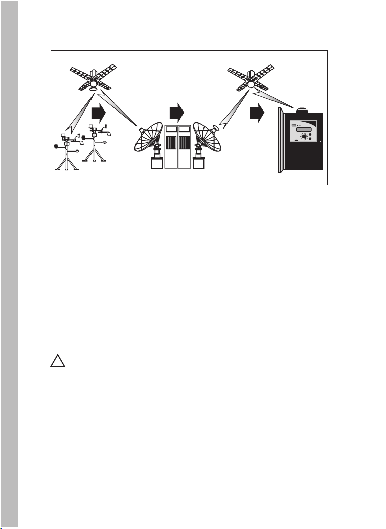
How the ET Everywhere Service Works
2 - Proven scientific modeling techniques are then used to
calculate and validate specific ET data down to one square
kilometer.
3 - The ET data is uploaded to a communications satellite
where it received nightly by the intelli-Sense controller to
automatically recalculate station-specific irrigation
parameters for the next scheduled watering day.
32
1
2
1 - The WeatherTRAK ET Everywhere service collects data
from over 25,000 monitoring stations including the National
Oceanic and Atmospheric Administration (NOAA) network,
state and county networks, and private weather stations.
Important: The ET Everywhere subsciption service is
!
not included with the purchase of the Intelli-Sense controller.
For service subscription information, contact WeatherTRAK
customer service at 1-800-362-8774 during normal business
hours.
Page 9
The following checklist provides the basic steps required for
Intelli-Sense Professional Controller installation, setup,
programming and operation.
Install per the provided intallation instructions. (See Installation
Instructions beginning on page 69).
Fill out the Intelli-Sense Control System Profile spreadsheet with
as much accurate detail as possible. Have the spreadsheet on
hand when performing the controller setup and programming
procedures.
Program the controller. This manual provides step-by-step
instructions for programming the controller based on the information captured on the System Profile spreadsheet.
3
Chapter 1
Getting Started
Thoroughly inspect the irrigation system for proper design,
installation and operating condition, leaks, as well as broken
heads and pipes. The performance of your new controller
depends on the integrity of the irrigation system design and
installation. You will maximize the performance of your
controller when the irrigation system is well maintained.
Activate the WeatherTrak ET Everywhere subscription service.
This necessary and important step enables the Intelli-Sense to
receive daily ET updates.
Page 10
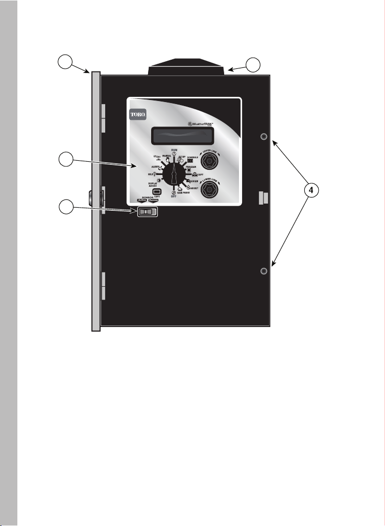
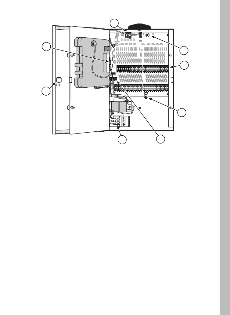
Controller Hardware Overview
2
TIS-PRO
1
5
3
1 - Intelli-Sense Control Module - (See page 6 for details.)
2 - Enclosure - Weather- and vandel- resistant heavy-gauge
steel cabinet with locking cover.
3 - Weatherproof External Anatenna - Provides exceptional
reception in most locations.
4 - Hinged Access Panel Fasteners - Thumbscrew fasteners
secure hinged control panel for ease of access without
5 - Rain Sensor Control Switch - Slide switch provides
manual override control of auxiliary rain sensor.
4
tools.
Page 11
8
7
VC/
VC/
25 26 27 28 29 30 31 32 33 34 35 36
25 26 27 28 29 30 31 32 33 34 35 36
MV/
1 2 3 4 5 6 7 8 9 10 11 12
PUMP
MV/
6
1 2 3 4 5 6 7 8 9 10 11 12
PUMP
37 38 39 40 41 42 43 44 45 46 47 48
COM
COM
VC/
VC/
37 38 39 40 41 42 43 44 45 46 47 48
COM
COM
VC/
VC/
13 14 15 16 17 18 19 20 21 22 23 24
COM
COM
VC/
VC/
13 14 15 16 17 18 19 20 21 22 23 24
COM
COM
9
10
11
13
6 - Control Module Latch - Enables control module
12
to be
easily removed without disturbing controller installation.
7 - Fuse - 2A Slo-Blo fuse provides short-circuit protection
on the 24 VAC output circuit.
8
- Flow and Rain Sensor Connection Terminal Block
Quick release wire terminals for easy, secure connections.
9
- TMR-1 Handheld Remote Connections - Provides
RJ-11 plug receptacle and 24 VAC power source for
TMR-1 handheld remote reciever connection.
- Valve Wire Connection Terminal Blocks - Screwless,
10
quick release control wire terminals for easy installation.
11 - Earth-ground Lug -
Heavy-duty ground lug accepts
10 AWG solid-copper wire from earth ground device.
12 - Hot Post - Provides a constant 24 VAC power sou
rce
to assist in valve identification for initial installation,
system service and troublshooting procedures.
13 - Main Power Connection Terminal Block - Screw
terminals for 120 VAC input power wires.
5
Page 12
Control Module Overview
17a
16a
18
14
15
17
16
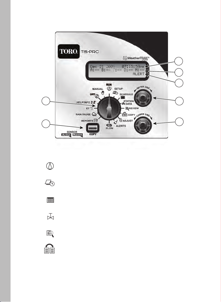
14 - Function dia l - Turn this dial in either direction to select
controller setup and operational functions:
RUN - The normal position for automatic operation.
Current time/date and controller activity is displayed.
1
SETUP - Select and define specific controller setup
and operating parameters.
SCHEDULE - Set up and adjust start times/water
windows and watering day schedules.
STATION DATA - Select and define specific station
setup and operating parameters.
REVIEW - Review current program information
for each station, and flow sensor setup and data log.
COPY - Transfer station or program information
from one station or program to another. Also used
to
reset station, setup and program default settings.
6
Page 13
o
ADJUST - Adjust station watering by 5% increase or
decrease of run time and/or watering days.
ALERTS - Display system problems and
operationalconflicts.
FLOW - Set flow meter attributes and operational
partameters.
REPORTS - Access and review station run time
flow data by day, week or month time periods.
and
RAIN PAUSE - Suspend automatic watering for a
period of 1 to 14 days.
ET - Display current daily and average weekly ET
values. Set custom Kc and weekly ET values.
Access various controller activation
HELP/INFO setup data, operational preferences, and status
information.
OFF - Terminate and suspend all watering activity.
MANUAL - Access manual watering operations.
15 -
Copy button – The Copy button is used in various
operations including copying and transferring station
and program data, restoring default settings and
reviewing various setup, station, and flow data.
16 - Lower Line knob - This knob is used to select and/or
adjust data viewed on the lower line of the display
(16a).
17 - Upper Line knob - This knob is used to select setup and
program control options shown on the upper line of the
display (17a ).
18 - Information Line - The third line of the display provides
supplemental information including the Alert prompt.
7
Page 14

Notes
8
Page 15
Chapter 2
Controller Setup
The SETUP function menu consists of 10 screens listed in
the following order:
•
Adjust Display Contrast
•
Set Controller Clock
• Set Time Zone
• Set Auto Daylight Savings option
• Set Maximum Active Stations
• Select Stack or Overlap option
• Set Master Valve Type/Pump Start option
• Select Runtime Valve Test
• Set Maximum Backup ET
About Controller Input
As you begin the controller setup procedures, you will find that
virtually all user-defined input is accomplished in the same
manner using the Function dial, Upper Line knob, and Lower
Line knob. For example, when you turn the Function dial to the
SETUP position, the first screen in the Setup menu will be
displayed. In this case, Adjust Display Contrast will be displayed
on the upper line and the default contrast value of 224 will be
displayed on the lower line.
ADJUST DISPLAY CONTRAST
224
The contrast value is underscorred and flashing, indicating that
it is selected and can be changed or edited by turning the Lower
Line knob. The information displayed on the screen when the
Upper Line knob or Function dial is turned in either direction,
enters the information into the controller memory.
9
Page 16
Set Controller Clock
1. With the Function dial in the SETUP position, turn the Upper Line
knob to select the following display:
DATE (YEAR)
Feb 24 2008
2. Turn the Lower Line knob to set the current year.
3. Turn the Upper Line knob right to select the next menu item,
Date (Month).
DATE (MONTH)
Feb 24 2008
4. Turn the Lower Line knob to set the current month.
5. Turn the Upper Line knob right to select
6. Turn the Lower Line knob to set the current day.
7. Turn the Upper Line knob right to select
8. Turn the Lower Line knob to set the current hour (am or pm).
9. Turn the Upper Line knob right to select
10. Turn the Lower Line knob to set the current minute.
Note: Leave the Function dial in the SETUP position to continue
selecting and setting the remaining Setup menu items.
10
Date (Day).
Time (Hour).
Time (Minute).
Page 17

Set Time Zone
1. Within the Setup menu, turn the Upper Line knob to view the
following display:
TIME ZONE
Pacific
2. Turn the Lower Line knob to select your time zone from the
following choices:
• Pacific (default setting)
• Alaska
• Hawaii
• Atlantic
• Eastern
• Central
• Mountain
Select Auto Daylight Savings Option
1. W
ithin the Setup menu , turn the Upper Line knob to view the
following display:
AUTO DAYLIGHT SAVINGS
Yes
2.
The default selection is Yes which enables the controller to
automatically compensate for Daylight Savings time. To disable
this option, turn the Lower Line knob to display No.
11
Page 18
1.
2.
Within the Setup menu, turn the Upper Line knob to view the
following display:
Note: The active station count entered in this step will also determine the
number of stations that can be accessed within the Programming , Review
and Copy function procedures.
MAX ACTIVE STATIONS
01 (User Defined)
Set Maximum Active Station Count
The actual number of stations being used for irrigation must be entered
to enable accurate automatic scheduleing.
12
To change the number of active stations, turn the Lower Line knob.
STA CONFIG FOUND ACIVE
36 36 36
Note: To review the current station configuration, press the Copy button
when SETUP function is selected.
Important: The Intelli-Sense Professional controller firmware
!
provides for the scheduling of 48 stations regardless of controller
output configuration. If the actual number of active stations is not
set accurately and/or set according to controller output configuration, alert errors and reuced controller performace will result. For
example, setting the active station count higher than actual will
result in an alert error or will add unnecessary time to the Water
Window. Setting the station count lower than actual will cause
some stations to be skipped.
Note: The abbreviated display information indicates the following:
STA CONFIG = Controller model configuration of 36 or 48 stations
FOUND = Actual number of stations recognized by controller
ACTIVE = Maximum active station count selected.
Page 19
1. Within the Setup menu, turn the Upper Line knob to view the
following display:
STACK OR OVERLAP
Stack
Select Stack or Overlap Option
When the Stacking option is selected, the controller will be
constrained to operate one station at a time. The Water Window
start time and duration selected for Automatic Schedule A will
also be assigned to Automatic Schedule B, C and D.
When the Overlap option is selected, the constraint is removed,
allowing multiple programs to run simultaneously.
When Overlap is selected, Start time and Water Window options
are available in all schedules.
!
Important: Prior to selecting the Overlap option,
confirm that the irrigation system hydraulic capacity and
the controller’s maximum current draw capacity (2.0A) will
not be exceeded if four stations and master valve circuit are
operated concurrently.
!
Important: When the STACK option is selected within the
Setup menu, the start time and water window parameters
defined for Program A will apply to all progams, and can not
be edited by individual program.
If the OVERLAP option is selected, separate start time and
water window parameters can be defined for each program.
The Stack option is seleted by default. To select theOverlap option,
2.
turn the Lower Line knob to display Overlap.
13
Page 20
1. Within the Setup menu, turn the Upper Line knob to view the
following display:
2. Turn the Lower Line knob to select the preferred option.
Note: If a pump station is in use but no master valve is required,
use the Normally Closed/Pump On option.
MASTER VALVE/PUMP START
Normally Closed/Pump On
ASSIGN PUMP START OUTPUT
NOT ASSIGNED
Set Master Valve/Pump Start Option
The controller features a dedicated master valve/pump start output
as a standard feature. The master valve is used to isolate the
mainline or a portion of the mainline when programmed as part of
flow monitoring. It enables the controller to troubleshoot and isolate
pipe malfunctions or other problems. Three choices provided are:
• Normally Closed/Pump On (default)
• Normally Open/Pump Off
• None
Assign Pump Start Output
The controller allows the user to assign a pump start to a station output,
effectively decreasing the controller station count by 1. The assigned
station will be active with all stations. This feature is typically used in
combination with a normally-open (NO) type master valve to enable the
pump to operate while the NO master valve remains de-engerized (open).
1. Within the setup Menu, turn the Upper Line knob to view the
following display:
2. Turn the Lower Line knob to select the station number to be designated as the pump start output.
14
Page 21
Set Maximum Backup ET
1. Within the Setup menu, turn the Upper Line knob to view the
following display:
Turn the Lower Line knob to adjust the decimal number value.
MAX BACKUP ET Part 1
2.00
The Maximum Backup ET value is a failsafe measure used by the
controller to calculate daily watering requirments in the event that
current ET Everywhere data is not recieved for an extended period.
2.
The Maximum Backup ET default value of 2.00 is automatically
entered to help compensate for seasonal weather changes.
The whole number of the Maximum Backup ET value is selected
by default. To adjust the value from 1 – 3, turn the Lower Line
knob.
Note: The Maximum Backup ET is adjustable from 0.50 – 3.99.
The whole number is only adjustable to 0 when the decimal
number value is .50 or higher.
4.
Turn the Upper Line knob right one stop to select the decimal
number.
3.
Set Runtime Valve Test Option
The controller features a Valve Test feature that will test each station
for a short-circuit condition each time it is activated. If a fault is detected,
an Alert will be posted, enabling identification and repairs to be made.
1. Within the Setup menu, turn the Upper Line knob to view the
following display:
RUNTIME VALVE TEST
No (Check Fuse Often)
2. Turn the Lower Line knob to select Yes or No as preferred.
15
Page 22

Notes
16
Page 23
Chapter 3
Set Program Schedule
1. Turn the Function dial SCHEDULE to view the following
display:
Program A is selected by default. The current watering day
schedule, start time and water window information is shown
for Program A.
SELECT PROGRAM
A (Optm S12:00am W16:00)
The Intelli-Sense Professional Controller enables four independent
program schedules (A, B, C and D) to be defined by one or two start
times with associated water window and a specific watering day
schedule. Each station is then assigned to one of the programs in
the Station Data function.
Important: When the STACK option is selected within the
!
Setup menu, the start time and water window parameters
defined for Program A will apply to all progams, and can not
be edited by individual program.
If the OVERLAP option is selected, separate start time and
water window parameters can be defined for each program.
Select Program
Note: The abbreviated display information indicates the following:
Optm = Watering day schedule is Optimized by WeatherTRAK
S12:00am = Start Time is 12:00 a.m.
W16:00 = Water window duration is 16 hours.
2. To change the program selection, turn the Lower Line knob to
select program B, C or D.
17
Page 24
Set Program Start Start Time and Water Window
1. Within the Schedule menu, turn the Upper Line knob to select
the following display:
SET STARTS/WINDOWS PRG A
Skip (Button to View)
Note: To review the current start time/water window settings,
press the Copy button. The abbreviated information will be
displayed as shown in the example below.
START 1 S12:00am W16:00
Off
Start 1 = 12:00 a.m., water window is 16 hours in duration,
and Start Time 2 is turned off.
2. Skip is selected by default. To edit the selected program, turn the
Lower Line knob to select Edit.
SET STARTS/WINDOWS PRG A
Edit (Button to View)
3. Turn the Upper Line knob to select the following display:
1st Start/Window PRG A
Start 12:00am Win 16:00
(Button to View)
4. The start time hour is underlined and flashing, indicating that it
can be edited. Turn the Lower Line knob to set the start time
hour, or turn the Upper Line knob right to select next element
of the screen to be edited.
18
Page 25
Repeat the editing procedure used to enter the 1st start time
andwater window.
8.
(Button to View)
5. Turn the Upper Line knob right to select water window duration.
1st Start/Window PRG A
Start 12:00am Win 16:00
(Button to View)
2nd Start/Window PRG A
Start 07:00pm Win 05:00
Note: Water window is the duration of time allotted for all stations,
assigned to the program to complete their programmed watering
cycle(s). The water window duration is adjustable from 1 hour to
23 hours and 59 minutes. The controller provides the water window
end time by factoring the selected start time and duration.
6. Turn the Lower Line knob to adjust number of hours, or turn the
Upper Line knob right to select minutes and edit as preferred.
Note: A second program start time/water window is provided for
automatic syringe watering where compensation for higher than
normal ET is desired. Labeled High ET start, the controller
automatically reduces the total station watering amount during this
syringe operation to 25% of normal.
To prevent operational conflicts due to overlapping watering
cycles, the following setup criteria must be considered:
• The 2nd start time cannot occur within the 1st start time cycle
• The combined water window duration cannot exceed 23 hours
and 59 minutes.
If an Overlap condition alert is posted, the source of the conflict
must be resolved. If not corrected, the 2nd start time will default to
the Off mode. Press the Copy button to compare settings. Also
refer to the Alerts function on page 44 for additional information.
7. Turn the Upper Line knob right to select the 2nd Start Type screen.
The High ET start time option is Off by defualt. To program, turn the
Upper Line knob right to display the following setup screen.
19
Page 26
Set Program Water Day Mode
Each program can be assigned to unique water day schedule using
one of the following options:
• Optimized by WeatherTRAK - Water day schedule selected
automatically by the Intelli-Sense scheduling engine.
• Odd/Even - Odd or Even numbered calendar days.
• Interval - Water days set by frequency ranging from 1 to 30 days.
• Days of Week - Specific days of the week (same all months)
• Days of Week by Month - Specific days of the week for each month.
• Off - Turn program off.
1. With the Function dial in the SCHEDULE position, turn the
Upper Line dial to view the following display:
WATER DAY MODE PRG A
Optimized by WeatherTRAK
2. Optimized by WeatherTRAK is selected by default.
To use this mode, continue at step 3. To use an alternate
mode, continue at the appropriate following section.
3. Turn the
that enables a weekday to be excluded from operation.
4. Turn the Lower Line
Odd/Even
1. Turn the Lower Line knob to select Odd/Even.
Upper Line knob to select the Day Exclusion feature
knob to display the day name or None.
WATER DAY MODE PRG A
Odd/Even
2. Turn the Upper Line knob to display Odd.
3. Turn the Lower Line
20
knob to select Even.
Page 27
Interval
1. Turn the Lower Line knob to select Interval.
WATER DAY INTERVAL PGM A
01 (Everyday)
2. The default Interval is 01 which schedules every day as active.
To select an Interval from 02 – 30, turn the Lower Line knob.
:etoN The current day is the first active day of the Interval
schedule. For example, if today is Saturday and a 02 interval
(water every-other-day) is set, today will be active. The next
active watering day will be Monday.
Days of Week
1. Turn the Lower Line knob to select Days of Week.
WATER DAY MODE PGM A
Days of Week
2.3.Turn the Upper Line knob to view the following display:
OK TO WATER ON PGM A
S M T W T F S
By default, every day is an active watering day. To remove days
from the schedule, turn the Upper Line knob to select the day
indicator, then turn the Lower Line knob to replace the indicator
with a dash (as shown in the following example).
OK TO WATER ON PGM A
S M - W T - S
21
Page 28

Days of Week by Month
1. Turn the Lower Line knob to select Days of Week by Month.
WATER DAY MODE PGM A
Days of Week by Month
2.3.Turn the Upper Line knob to view the following display:
Jan OK TO WATER ON PGM A
S M T W T F S
By default, every day of every month is an active watering day.
To omit specific days from specific months, turn the Upper Line
knob to select the month.
To omit specific days, turn the
4.
indicator, then turn the Lower Line knob to replace the indicator
with a dash (as shown in the following example).
Upper Line knob to select the day
Jan OK TO WATER ON PGM A
S M - W T - S
Water Day Mode Off
Selecting the Off water day mode effectively prevents the program from
running automatically. To reinstate a program to automatic operation,
simply choose an alternate watering day mode.
1. Turn the Lower Line knob to select Off. .
WATER DAY MODE PGM A
Off
22
Page 29

Chapter 4
Station Data Setup
The Station Data function menu consists of several station setup
parameters required for automatic operation.
Four station operating mode options provide the control flexability to
program each station for optimum irrigation control.
The station operating mode selections are:
• Automated by WeatherTRAK
• User - With ET (user-defined setup parameters with ET control)
• User - No ET (user-defined setup parameters without ET control)
• Off (station disabled)
Within each operating mode are the following required setup
parameters:
Automated By WeatherTRAK:
• Select Station
• Select Station Mode • Select Station Mode
• Select Program
• Water Window option
• Usable Rainfall
• Sprinkler Type
• Precipitation Rate*
• Sprinkler Efficiency*
• Soil Type
• Plant Type
• Root Depth*
• Microclimate
• Slope Factor
• Sprinkler Location (on slope)
As you can see by the extent of these lists, many factors are required
to formulate an accurate baseline watering schedule. To simplify
this procedure, Intelli-Sense will select default values based on your entries.
You can adjust these values if needed. The items listed with an asterisk (*) will
have default values based on the selection made in preceding setup parameter.
User Defined:
• Select Station
• Select Program
• Water Window option
• Usable Rainfall
• Run Time
• Number of Cycles
• Soak Time
• Reference ET
User - With ET mode only)
• Reference Month (applies to
User - With ET mode and
watering days by month only)
(applies to
Note: To begin the setup process, select Automated by WeatherTRAK
mode on page 24, or User-defined modes starting on page 33.
23
Page 30

Station Setup Mode: Automated by WeatherTRAK
Select Station
1. Turn the Function dial to the STATION DATA position.
The Select Station menu item is displayed by default.
SELECT STATION
01
2. Station 01 is selected by default. To change the station number,
turn the Lower Line knob.
Note: The Maximum Active Station number defined in Setup,
determines station number access.
Select Station Mode
1. Turn the Upper Line knob to display Station Mode.
STATION MODE STA 01
Automated by WeatherTRAK
2. Automated by WeatherTRAK mode is selected by default.
If it is not displayed, turn the Lower Line knob to select.
Select Program
1. Turn the Upper Line knob to display Select Program.
SELECT PROGRAM STA 01
A (Optm S12:00am W16:00)
2. Program A is selected by default. To change the program selection,
turn the Lower Line knob.
24
Page 31

Select Water Window Option
Use Water Window STA 01
Yes (end time 04:00pm)
Select Sprinkler Type
SPKLR TYPE
Spray Head
2. Spray Head is selected by default. To choose from the menu of
listed sprinker types, turn the Lower Line knob.
1. Turn the Upper Line knob to display Sprinkler Type
Select Usable Rainfall
USABLE RAINFALL
100%
2. 100% is selected by default. To decrease the value, turn the
Lower Line knob right.
1. Turn the Upper Line knob to display Usable Rainfall.
1. Turn the Upper Line knob to display Use Water Window.
The current water window end time is automatically calculated
and displayed for the selected program.
2. Yes is selected by default. To disable the water window for the
selected station, turn the Lower Line knob to select No.
Note: By selecting No, the station will run until irrigation is
complete, regardless of the water window established for
the program.
The Usable Rainfall setting defines the percentage of the station’s
watering area exposed to rainfall. This setting is adjustable from
None (no rain contact) to 100% (full rain contact) in 25% increments.
For example, about 25% of the station zone is covered by a roof
overhang. The usable rainfall value for this station would be 75%.
25
Page 32

Set Precipitation Rate
!
Important:The sprinkler precipitation rate (PR) is a key
factor in the calculation of an automatic watering program.
If you know the actual PR value, enter it at this time. If you do
not have this information, the baseline PR of the sprinkler
type (entered in the previous step) will be entered.
1. Turn the Upper Line knob to display Precip Part 1.
PRECIP PART 1 STA 01
1.70 Inches/Hr (default)
2. The default PR value will be displayed for the sprinkler type
selected. The whole number is selected in Part 1. Turn the
Lower Line knob to adjust the value from 0 – 9.
Note: The PR value is adjustable from 0.10 – 9.99 Inches/Hour.
The whole number value is adjustable to 0 only when the
decimal number value is ≥ 10. Conversely, the decimal number
is adjustable to 0 when the whole number is ≥ 1.
3. Turnthe Upper Line knob right one stop to select the decimal
number (Part 2).
PRECIP PART 2 STA 01
1.70 Inches/Hr (default)
4. Turn the Lower Line knob to adjust the decimal number value
from 00–99.
26
Page 33

The default efficiency value is displayed for the sprinkler type
selected. To change the value, turn the Lower Line knob to
adjust the value from 10 – 95%.
2.
SPKLR EFFICIENCY
STA 01
70 Percent (default)
Set Sprinkler Efficiency
Like the sprinkler PR value, the Sprinkler Efficiency value is a key
factor used by the Intelli-Sense to calculate an efficient watering
program for each station. The controller will automatically enter an
efficiency value based on the type of sprinkler selected for the station.
Changing the efficiency value will alter overall station watering
operation as follows:
▲ Increasing sprinkler efficiency (sprinkler performs above average),
decreases overall watering.
▼ Decreasing sprinkler efficiency (sprinkler performs below average),
increases overall watering.
1. Turn the Upper Line knob to display Spklr Efficiency.
Select Soil Type
1. Turn the Upper Line knob to display Soil Type.
SOIL TYPE
STA 01
Sandy
The soil type displayed is the default for the sprinkler type
2.
selected. To change the soil type, turn the Lower Line knob
to select one the following options:
• Sandy
• Sandy Loam - Higher percentage of sand than clay
• Loam - Equal percentage of sand and clay
• Clay Loam - Higher percentage of clay than sand
• Clay.
27
Page 34

Select Plant Type
Within the Program menu, turn the Upper Line knob to select
Plant Type.
PLANT TYPE STA 01
Cool Season Turf (default)
2.
1.
The default Plant Type will be displayed, Cool Season Turf.
To select an alternate Plant Type, turn the Lower Line knob.
3.
Plant factors corresponding to the custom types can be set
in the ET menu.
Select from the following Plant Type selections that best matches
the plant material in the station:
• Cool Season Turf
• Warm Season Turf
• Combined Turf
• Annuals
• Ground Cover
• Trees
• Shrubs – High Water Use
• Shrubs – Medium Water Use
• Shrubs – Low Water Use
• Mixed – High Water Use
• Mixed – Medium Water Use
• Mixed – Low Water Use
• Native Shrubs/Trees
• Native Grasses
• Custom Plant A
• Custom Plant B
• Custom Turf
28
Page 35

Notes
29
Page 36

Set Root Depth
SET ROOT DEPTH STA 01
06 Inches (default)
Within the Program menu, turn the Upper Line knob to select
1.
Set Root Depth.
The default root depth will be displayed for the soil type and
2.
plant type previously selected. To change the depth, turn the
Lower Line knob to adjust from 2 – 36 inches.
Note:
▲ Increasing the Root Depth value (root depth greater than average),
increases overall watering.
▼ Decreasing the Root Depth value (root depth less than average),
decreases overall watering.
Select Microclimate
The station Microclimate value is the average exposure to sunlight and
shade throughout the day. One of following four Microclimate options
is selected that best describes the average conditions for the station:
Sunny All Day = Sun for 7 to 8 hours per day – no change to
•
the calculated ET rate.
Sunny Most of the Day = Sun for 4 to 6 hours per day –
•
decreases watering by 10% of calculated ET rate.
Shady Most of the Day = Shady for 4 to 6 hours per day –
•
decreases watering by 20% of calculatd ET rate.
Shady All Day = Shady for 7 to 8 hours per day – decreases
•
watering by 30% of calculated ET rate.
Turn the Upper Line knob to select Set Microclimate.
1.
30
SET MICROCLIMATE STA 01
Sunny All Day
Sunny All Day is selected by default. To select an alternate
2.
microclimate, turn the Lower Line knob.
Page 37

Select Slope Factor
The SlopeFactor is an important component used in the automatic
watering program calculation to determine the amount of run time and
number of repeat cycles required per watering day.
The Slope Factor options are as follows:
• 0 – 5% Grade
None/Slight
• 6 – 8% Grade
Gentle
• Mild 9 – 12% Grade
1. Turn the Upper Line knob to select Set Slope Factor.
• Moderate 13 – 20% Grade
• Steep >20% Grade.
SET SLOPE FACTOR STA 01
None/Slight 0-5% Grade
2.
None/ Slight (0 –5%) grade is selected by default. To select
an alternate Slope Factor, turn the Lower Line knob.
Note: To prevent runnoff, selecting any slop factor other than
None/Slight will result in a decrease in station run time per
cycle and an increase in the watering cycle frequency.
Select Sprinkler Location
Note: If a Slope Factor of None/Slight is selected, Sprinkler Location
setting is not enabled.
1.2.Turn the Upper Line knob to select Sprinklr Location.
SPRINKLR LOCATION STA 01
None, No Slope Set
None, No Slope Set is selected by default. To choose an
alternate Sprinkler Location, turn the Lower Line knob
to select one of the following options:
• All Parts of Slope (default if Slope Factor is other than None)
• Top of Slope
• Middle of Slope
• Bottom of Slope.
31 9
Page 38

Completing Station Setup
1.2.Turn the Upper Line knob to select Station (01) Complete.
STATION 01 COMPLETE
The next station number in sequence will be selected. To select
a different station, turn the Lower Line knob. Turn the Upper Line
knob to continue with the station setup procedure.
Important: To set up additional stations with the same
!
or similar operating parameters, use the COPY function to
transfer station setup data from one station to another or to
all stations at the same time. Minor adjustments to individual
stations can then be made quickly and easily. See Using the
Copy Function on page 38 for details.
Station Setup Modes: User Defined
Within the User-defined station mode are two format options:
User - With ET and User - No ET. Both formats require the same basic
setup process, with the exception that User - With ET mode enables a
Reference ET and (optional) Reference Month value to be selected.
When the User - With ET option is used, the station’s baseline watering
progam is updated daily by the ET Everywhere service and adjusted
automatically to suit current ET conditions.
When the User - No ET option is used, the station’s watering progam
remains constant, without regard to changes in ET.
A User-defined watering program is established for the station with the
setup parameters in the following menu order:
• Select Station
• Select Program
• Select Water Window option
• Set Usable Rainfall
• Set Run Time
• Select Number of Cycles
• Set Soak Time
• Set Reference ET (User - With ET format only)
• Set Reference Month (optional)
32
Page 39

Select Station
1. Withthe Function dial in the Station Data position, turn the
Upper Line knob to display Select Station.
SELECT STATION
01
2. Station 01 is selected by default. To change the station number,
turn the Lower Line knob.
Note: The Maximum Active Station number defined in Setup,
determines station number access.
Select Station Mode
1. Turn the Upper Line knob to display Station Mode.
STATION MODE STA 01
User - With ET
2. Turn the Lower Line knob to select Use - With ET or User - No ET.
Select Program
1. Turn the Upper Line knob to display Select Program.
SELECT PROGRAM STA 01
A (Optm S12:00am W16:00)
2. Program A is selected by default. To change the program selection,
turn the Lower Line knob.
Select Water Window Option
1. Turn the Upper Line knob to display Use Water Window.
Use Water Window STA 01
Yes (end time 04:00pm)
2. Yes is selected by default. To enable the station to ignore a water
window constraint, turn the Lower Line knob to select No.
33
Page 40

Select Usable Rainfall
The Usable Rainfall setting defines the percentage of the station’s
watering area exposed to rainfall. This setting is adjustable from
None (no rain contact) to 100% (full rain contact) in 25% increments.
For example, about 25% of the station zone is covered by a roof
overhang. The usable rainfall value for this station would be 75%.
1. Turn the Upper Line knob to display Usable Rainfall.
USABLE RAINFALL
100%
2. 100% is selected by default. To decrease the value, turn the
Lower Line knob right.
Set Station Run Time
The station run time defines how long the station will operate during
the watering cycle. The run time is adjustable from 1 to 99. 9 minutes.
1. Turn the Upper Line knob to display Runtime Part 1.
RUNTIME PART 1 STA 01
05.0 Minutes
2. Turn the Lower Line knob to adjust the whole number value
from 01 to 99.
3. Turn the Upper Line knob right to select the decimal value
(Runtime Part 2).
4. Turn the Lower Line knob to adjust the decimel number value
from 0 to 9.
34
Page 41

Select Number of Cycles
1. Turn the Upper Line knob to select Number of Cycles.
NUMBER OF CYCLES STA 1
01 Cycles/Operating Day
2. The number of watering cycles per watering day is set to 1 by
default. To adjust the number between 0 – 20 cycles per operating
day, turn the Lower Line knob.
Note: Selecting 0 cycles will prevent the station from operating
during automatic watering operations.
Set Soak Time
Soak Time is an adjustable delay period that occurs between station
watering cycles to help promote deeper rooting, and to avoid pooling,
runoff and soil erosion. Soak Time is adjustable from 0–480 minutes in
10-minute increments.
Note: The Soak Time is actually the minimum delay that can
occur before the station can run again. The actual delay period
may be longer due to the programming variables of other stations
assigned to the same watering program.
1. Turn the Upper Line knob to select Set Soak Time.
SET SOAK TIME STA 01
30 Minutes
2. The default Soak Time is 30 minutes. To adjust the soak time,
turn the Lower Line knob (00–480 minutes).
35
Page 42

Set Reference [weekly] ET Value (applies to User With ET mode only)
The Reference ET is the weekly ET set in the User – With ET mode that
your runtimes correspond to. Runtimes will be adjusted up or down
automatically depending on whether the actual weekly ET is higher or lower
than the Reference ET. The default Reference ET is 1.00 (0.14 inches per day).
It is recommended that you set runtimes and the Reference ET value based
on the highest weekly ET demand period of the year.
1.
Turn the Upper Line knob to view the following display:
REF. ET PART 1 STA 01
1.00 (Weekly ET 1.00)
2. The whole number of the Reference ET value is selected by default.
To adjust the value from 1 – 3, turn the Lower Line knob.
Note: TheReference ET value is adjustable from 0.50 – 3.99.
The whole number is only adjustable to 0 when the decimal
number value is .50 or higher.
3. Turn the Upper Line knob right to select the decimal
4.
Turn the Lower Line knob to adjust the decimal number value.
Note: If the station uses the Days of Week by Month,
watering day mode, the Reference Month screen will be
displayed as shown below. To adjust this setting, continue at
step 5. If not applicable, the Program Complete screen will
be shown.
5. Turn the Upper Line knob to view the following display:
REFERENCE MONTH STA 01
Jul (If Days by Month)
6. Turn the Lower Line knob to select the preferred month.
36
number.
Page 43

Chapter 5
Support Functions
The Setup, Schedule and Station Data functions enable you to set up
an automatic watering schedule designed specifically or each watering
zone of the landscape.
The support functions provide enhanced control capabilities of your
irrigation system; enabling you to perform various operations such as:
program data copy, review, fine-tuning to resolving actual and
potential irrigation problems, as well as providing a means of manually
operating the irrigation system.
Within this chapter you will find detailed instructions provided for
each of the support functions on the following pages:
Function Page
REVIEW . . . . . . . . . . . . . . . . . . . . . . . . . . . . . . . . . . . . . . . . . . . . . . . . 38
COPY . . . . . . . . . . . . . . . . . . . . . . . . . . . . . . . . . . . . . . . . . . . . . . . . . . 40
% ADJUST . . . . . . . . . . . . . . . . . . . . . . . . . . . . . . . . . . . . . . . . . . . . . . 44
ALERTS . . . . . . . . . . . . . . . . . . . . . . . . . . . . . . . . . . . . . . . . . . . . . . . . 46
FLOW . . . . . . . . . . . . . . . . . . . . . . . . . . . . . . . . . . . . . . . . . . . . . . . . . . 47
REPORTS . . . . . . . . . . . . . . . . . . . . . . . . . . . . . . . . . . . . . . . . . . . . . . . 53
RAIN PAUSE . . . . . . . . . . . . . . . . . . . . . . . . . . . . . . . . . . . . . . . . . . . 55
MAINTENANCE TIMEOUT 56
ET . . . . . . . . . . . . . . . . . . . . . . . . . . . . . . . . . . . . . . . . . . . . . . . . . . . . . 57
HELP/INFORMATION . . . . . . . . . . . . . . . . . . . . . . . . . . . . . . . . .
MANUAL . . . . . . . . . . . . . . . . . . . . . . . . . . . . . . . . . . . . . . . . . . . . . . 62
RUN/OFF . . . . . . . . . . . . . . . . . . . . . . . . . . . . . . . . . . . . . . . . . . . . . . 64
. . . . . . . . . . . . . . . . . . . . . . . . . . . . . .
. 59
37
Page 44

Using the Review Function
The Review function provides a convenient, at-a-glance overview
of all relavent station and flow monitro setup information.
1. Turn the Function dial to the REVIEW position. Review Mode will
be displayed.
REVIEW MODE
Station Data
2. Station Data is selected by default. To select Flow Data, turn the
Lower Line knob. (Refer to Flow Data Review on page 37.)
Station 1 will be selected by default. To select a differ ent station
3.
to review, turn the Upper Line knob.
The review information is displayed in an abbrevieated format that
allows the information to viewed in one screen as shown in the
example below.
1 2 3
ST01 A 11.9 MIN 01X AUTO
Wk1:-––T-– +00% Soak 30
4 5 6
(1) Station number 1 is assigned to watering Schedule A.
(2) The station will water for 11.9 minutes, one cycle per day.
(3 Automated by WeathTRAK is the assigned station mode.
If the station mode is User-No ET, User will be displayed.
UwET indicates station is assigned to User with ET mode.
(4) The active watering day schedule for Week 1 is Thursday.
Note: The remainder of the 8-week watering day schedule can be
viewed by turning the Lower Line knob.
(5) The % Adjust factor is +00%.
(6) Soak time is set for 30 minutes.
Note: Additional review information can be acquired for each station
by pressing the Copy button when the Fucntion dial is in the
STATION DATA position.
38
Page 45

Flow Data Review
1. With the Function dial in the REVIEW position, turn the Lower
Line knob to display Flow Data.
REVIEW MODE
Flow Data
2. Turning the Upper Line knob right displays the Flow Data review
screens in the following sequence:
• Master Valve Status
• View Excluded Stations
• Flow Meter Status/Size
3. All Flow Review screens are self explanitory, with the exception of
View Excluded Stations. The initial screen provides a Skip/View
option. To review the stations excluded from flow monitoring, turn
the Lower Line knob to select View.
• Flow Meter K and Offset Value
• Flow Thresholds (GPM)
• Flow Delay (Minutes)
VIEW EXCLUDED STATIONS
View (No Flow Only)
4. Turn the Upper Line knob right to display the first 8 stations.
Continue turning the knob right to display additional stations.
01 02 03 04 05 06 07 08
N N N N N N Y Y
In the example above, station 7 and 8 are excluded from the flow
monitoring function.
39
Page 46

Using the Copy Function
The Copy function provides a convenient method of transferring
all watering program information from one station to another or to
all active stations simultaniously. Minor changes can then be made to
each station as needed, greatly simplifying the process of programming
several stations with similar watering progam attributes.
The Copy function also serves as a means of quickly resetting all userdefined Setup, Schedule and Program settings back to the factory-default
values. The default values can be reapplied to selected stations or all
stations simultaniously as needed.
Copying Station Information
1. Turn the Function dial to COPY to view the following
display:
COPY FROM STA 01 TO
STA 02 (Press Button)
2. Turn the Upper Line knob to select the source station number.
Note: The number of active stations defined in the Setup function,
determines the number of stations that can be selected.
3. Turn the Lower Line knob to select the destination station number.
To select All Stations, turn the Lower Line knob one stop past the
highest station number, as shown in the following display:
COPY FROM STA 01 TO
ALL STA’s (Press COPY)
4. Press and hold the Copy button. Release the button when
Copying... Done! is displayed.
COPYING...DONE!
40
Page 47

Restoring STATION Default Settings
Important: Restoring the STATION defaults erases
!
and resets all user settings for all stations as follows:
Station Mode Program Mode - A
Use Water Window - Yes
Usable Rainfall - 100%
Sprinkler Type - Spray Head
Precipitation Rate - 1.70 In/Hr
Sprinkler Efficiency - 70%
1. Turn the Function dial to the COPY position.
Automated By WT
Soil Type Plant Type - Cool Season Turf
Root Depth - 6 Inches
Microclimate - Sunny All Day
Slope Factor - None/Slight
Sprinkler Location - None
Sandy
COPY FROM STA 01
To STA 02 (Press COPY)
2. Turn the Upper Line knob to select Copy Station Defaults
as shown in the following example:
COPY STATION DEFAULTS TO
To STA 02 (Press Button)
3. Turn the Lower Line knob to select the station number to be
restored. Or, to restore defaults to all stations , turn the
Lower Line knob to select All Stations.
COPY STATION DEFAULTS TO
ALL STA’s (Press BUTTON)
Press and hold the Copy button. Release the button when
4.
Copying Done is displayed.
COPYING...DONE!
41
Page 48

Restoring PROGRAM Default Settings
Important: Restoring the default Program settings erases
!
and resets all user-defined settings for all programs as follows:
1st Start Time - 12:00am
Water Window - 16:00
2nd Start Type - High ET
2nd Start Time - 07:00 pm
1. Turn the Function dial to the COPY position.
Water Window - 05:00
Water Day Mode - Optimized by WT
Day Excusion - None
COPY FROM STA 01 TO
STA 02 (Press BUTTON)
2. Turn the Upper Line knob to select Copy Program Defaults
as shown in the following example:
COPY PROGRAM DEFAULTS TO
PGM A (Press Button)
Turn the Lower Line knob to select the program A, B, C or D) to
3.
be restored. Or, to restore defaults to all programs simultaneously,
turn the Lower Line knob to select All Pgm.
42
COPY PROGRAM DEFAULTS TO
ALL PGM (Press Button)
Press and hold the Copy button. Release the button when
4.
Copying Done is displayed.
COPYING...DONE!
Page 49

Restoring SETUP Default Settings
Important: Restoring the SETUP defaults erases
!
and resets all user-defined settings as follows:
Adjust Display - 224
Date - No change
Time - No change
Time Zone - No change
Auto Daylight Savings - Yes
Active Stations - No Change
1. Turn the Function dial to the COPYposition.
Stack or Overlap - Stack
Master Valve - Normally Closed
Pump Start - Pump On
Run Time Valve Test - No
Max. Backup ET - 2.00
Flow Meter Mode - Off
COPY FROM STA 01 TO
STA 02 (Press BUTTON)
2. Turn the Upper Line knob to select Copy Setup Defaults.
COPY SETUP DEFAULTS
(Press Button)
Press and hold the Copy button. Release the button when
3.
Copying Done is displayed.
COPYING...DONE!
Copy Station Mode
If the controller is initially programmed in the field using the
Auto Station mode, but is left running in the User No ET mode,
e.g., for landscape establishment, the Auto Station settings are stored
in the controller memory. The Copy Station feature allows stations in
User No ET mode to be quickly copied to the Auto Station mode.
43
Page 50

Using the % Adjust Function
The % Adjust function allows you to make minor changes in overall
station irrigation rate by increasing or decreasing the watering program
values proportionally by percentage. Adjustments can be made in
5% increments by Water Amount (station run time and cycles per day),
and by Day Frequency/Maximum Allowable Depletion (MAD).
Note: Both adjustment methods can be applied to each active station,
however, DF/MAD is only available to stations operating in the
Automated by WeatherTRAK mode.
!
Important: A small percentage adjustment can result in
a significant change in irrigation rate. Always adjust in 5 or 10%
increments, then monitor the condition of the landscape for
7 to 10 days prior to making additional adjustments.
1. Turn the Function dial to % ADJUST. The Water Amount
adjustment option is selected by default.
ADJUST
Water Amount
2. To adjust by Water Amount factors, continue below. To adjust by
Day Frequency/MAD, continue on page 43.
% Adjust by Water Amount
1. Turn the Upper Line knob to select the station number.
ADJ WATER AMOUNT STA 01
0% = No Change
2. The unadjusted water amount value is 0%. Turn the Lower Line knob
right to increase, or left to decrease the value in 5% increments.
Maximum adjustment range is +25 to –50%.
ADJ WATER AMOUNT STA 01
+05% = More Water
44
Page 51

% Adjust by Day Frequency/Maximum Allowable Depletion
Stations assigned to the Automated by WeatherTRAK station mode
can be % adjusted by watering Day Frequency/Maximum Allowable
Depletion. For example, when establishing new turf, total water
application can be increased while decreasing the possibility of
runoff. Day Frequency is adjustable from -30% to +30% in 5%
increments. The equivalent MAD value will be displayed ranging
from 20% to 80% (with 50% being the standard depletion rate).
Turn the Lower Line knob to select Day Frequency/Depletion
1.
adjustment option.
ADJUST
Day Frequency/Depletion
2. Turn the Upper Line knob to select the station number.
ADJUST DAYS (MAD) STA 01
0% = No Change (50%)
Note: If the selected station number is assigned to a User-defined
station mode, the following display will be shown:
ADJUST DAYS (MAD) STA 06
Non-Adjustable Mode
3. Turn the Lower Line knob right to increase or left to decrease
the percent value. Maximum adjustment range is +30% to -30%.
Note: In the following example, the watering day frequency for
station 1 has been increased by 5%, which decreased the MAD
value to 45%. This change translates to irrigation being permitted
when soil moisture content drops to 45% instead of the standard
50% MAD value.
ADJUST DAYS (MAD) STA 01
+05% = More Often (45%)
45
Page 52

Using the Alerts Function
If a problem, confilict or error occurs with one of the essential
Intelli-Sense functions, an Alert prompt will be immediately posted.
Selecting Alerts function provides a quick overview of the monitored
functions, and flags the source of the alert condition.
1. Turn the Function dial to the ALERT position.
FL VL CM WD DY HW SB
-- ER -- -- —— —— ––
——=Ok ER=Error
From the initial Alert display screen, the specific function causing
the alert condition will be identified as follows:
FL - Flow Status
VL - Valve Status
CM - Communication Status
WD - Water Window Status
2. Turn the Upper Line knob to select the function to review.
The current status will be displayed, and if additional data is
available, a Skip/View option will be provided.
3. To view the additional data, turn the Lower Line knob to select
View. Turn the Upper Line knob to display the data.
Note: When the condition has been resolved, the Alert display
prompt will be removed.
Example: Valve Status Alert
1. With the ALERTS function selected, turn the Upper Line knob
right to select View Valve Status.
DY - Water Day Status
HW - Hardware Status
SB - Subscription (ET) Status
VIEW VALVE STATUS
Skip Short
2. Turn the Lower Line knob to select View.
3. Turn the Upper Line knob right as needed to display the affected
station number(s).
01 02 03 04 05 06 07 08
-- -- SH -- —— —— —— ––
SH=Short NC=NoConnect
46
Page 53
Using the Flow Monitor Function
The Intell-Sense Professional Controller incorporates a precision
flow monitorfunction to display and record flow data provided by
a compatible Toro TFS Series or Data Industrial IR Series flow
sensor. (See flow sensor installation details on page 75.) With the
flow sensor properly installed and configured for operation,the
Intelli-Sense will continually monitor flow sensor input to record
and respond to specific flow conditions including: High-flow,
Non-flow, and Leakage. Each flow parameter has an adjustable
alert threshold and response delay period. During system operation, any monitored flow condition detected outside the threshold
will initiate anAlertresponse. The controller will automatically
turn off any affected station(s) or the entire irrigation system as
warranted by the monitored condition.
1. Turn the Function dial to the FLOW position. The Measured
Flow review screen is displayed by default and provides the
current system GPM flow rate.
MEASURED FLOW (GPM)
FM1: 000.0
Note: Pressing the Copy button while the Flow function is
selected will prompt the Measured Flow screen to display the
current flow rate.
2. Turn the Upper Line knob right to select Flow Meter Mode.
FLOW METER MODE
Off
3. By default, the flow monitor function is Off. To turn the
monitor function On, turn the Lower Line knob to select 1.
FLOW METER MODE
1
47
Page 54

Set Station Exclusion
The station exlusion feature enables individual stations to be omitted
from the Flow Monitor operations.
1. With the the Function dial in FLOW position, turn the Upper Line
knob right to select Edit Excluded Stations.
EDIT EXCLUDED STATIONS
Skip (No Flow Only)
2. Turn the Lower Line knob to change Skip to Edit.
3. Turn the Upper Line knob to display the first eight station numbers
in sequence.
01 02 03 04 05 06 07 08
N N N N N N N N
4. By default, no stations are excluded (indicated by N) and station
01 is selected. To exclude the selected station, turn the Lower Line
knob to change N to Y (Yes). To select another station number, turn
the Upper Line knob. Repeat as needed for all station numbers.
Set Flow Meter Size
1. With the the Function dial in FLOW position, turn the Upper Line
knob right to select Set Flow Meter Size
SET FLOW METER SIZE
1.00”
2. Turn the Lower Line knob to select the actual flow sensor size from
the following options: 1.00”, 1.25”, 1.50”, 2.00”, 3.00”, 4.00” and
Insert Type (sizes < 1” or > 4”).
48
Page 55

Edit Flow Sensor K Value and Offset
A default flow sensor K value, based on the flow sensor size, is
automatically entered. Refer to the manufacturer’s recommended
K value and edit accordingly.
1. With the the Function dial in FLOW position, turn the Upper Line
knob right to select Edit K Value.
EDIT K VALUE FOR 1:00”
Skip 00.397368 (default)
2. Turn the Lower Line knob to change Skip to Edit.
EDIT K VALUE FOR 1:00”
EDIT 00.397368 (default)
3. Turn the Lower Line knob to select the edit screen. The first digit
in sequence will be selected. To adjust the digit, turn the
Lower Line knob. To advance to the next digit, turn the
Upper Line knob. Repeat this process for the remaining digits
to be edited.
EDIT K VALUE FOR 1:00”
00.397368 (default)
4. Turn the Upper Line knob right to select Edit Flow Offset.
EDIT FLOW OFFSET 1.00”
Skip +00.261768 (default)
5. Edit the Flow Offset value in the same manner as K Value.
49
Page 56

Set Threshold and Delay Values
The threshold value is the defined limit for maximum, minimum and
no-flow conditions. If monitored flow exceeds a threshold, an Alert is
posted, and all remaining watering operations suspended or modified untl
the alert is cleared or problem resolved.
The delay period provides a 1- to 6-minute buffer between an exceeded
threshold and the controller response. Increasing the delay period,
decreases controller sensitivity to temporary or minor fluctuations.
Controller Response: Controller response to an exceeded threshold
is based on the selected operating mode as follows:
Stack Mode – The operating station will turn of f, and the next station in
sequence will turn on. If the condition persists, all irrigation will be
terminated and an alert posted. If the flow normalizes, the controller will
continue the watering cycle. Bypassed stations will be indicated and
given first priority in the next schedueld watering cycle.
Overlap Mode – The system will shut down. After a short delay , the
master valve will be opened and flow measured. If the condition
persistes, all irrigation will be terminated and an alert posted. If flow
normalizes, watering will resume one station at a time. Each station will
be flow monitored and bypassed if the threshold is exceeded. Bypassed
stations will be indicated and given first priority in the next schedueld
watering cycle.
Setting the High Flow Threshold
Note: The High Flow threshold should be set approximately 10–15%
higher than the expected flow in any program configuration to prevent a
false alert response.
1. With the the Function dial in FLOW position, turn the Upper Line
knob right to select High Flow Threshold.
HIGH FLOW THRESHOLD
050 GPM 3 Minutes
2. The default threshold will be displayed. To adjust, turn the Lower
Line knob. The value is adjustable from Off –30 in one-GPM
increments, or 30–995 in five-GPM increments.
50
Page 57
3. Turn the Upper Line knob (right) to select High Flow Delay.
HIGH FLOW DELAY
050 GPM 3 Minutes
4. Turn the Lower Line knob to adjust the delay minutes (1–6).
Setting the No Flow Threshold
Note: To prevent a false alert response, the No Flow threshold should be
set 10–15% lower than the expected flow in any program configuration.
1. Turn the Upper Line knob (right) to select No Flow Threshold.
NO FLOW THRESHOLD
005 GPM 3 Minutes
2. The default threshold will be displayed. To adjust, turn the Lower
Line knob. The value is adjustable from Off –30 in one-GPM
increments, or 30–995 in five-GPM increments.
3. Turn the Upper Line knob (right) to select No Flow Delay.
NO FLOW DELAY
005 GPM 3 Minutes
4. Turn the Lower Line knob to adjust the delay period (1–6 minutes).
51
Page 58

52
Setting the Leak Detection Threshold
Note: Flow is monitored during non-irrigation periods (outside of scheduled
irrigation or during soak periods) to detect leaks. If flow is monitored above
the Leak Detect threshold, the master valve will be shut off and an alert
will be posted. The alert condition must be cleared to resume operation.
1. Turn the Upper Line knob (right) to select Leak Detect Threshold.
LEAK DETECT THRESHOLD
015 GPM 3 Minutes
2. The default threshold will be displayed. To adjust, turn the Lower
Line knob. The value is adjustable from Off –30 in one-GPM
increments, or 30–995 in five-GPM increments.
3. Turn the Upper Line knob (right) to select Leak Detect Delay.
LEAK DETECT DELAY
015 GPM 3 Minutes
4. Turn the Lower Line knob to adjust the delay period (1–6 minutes).
Note: If Manual Irrigation or Quick Couplers are used, the Leak Detect should
be set above the expected flow for these operations.
Page 59

53
Using the Reports Function
The Reports function provides cumulative station run time and flow data,
selectable within the following specified reference formats:
Weekly Stations - Run time in hours and minutes per station per week.
Monthly Stations – Run time in hours and minutes per station per month.
Flow – Total flow in gallons per day, week, month, specific day range and
specific prior date.
Weekly Stations Report
1. Turn the Function dial to the REPORTS position.
REPORTS TYPE
Weekly Stations
2. Weekly Stations is selected by default.
3. Turn the Upper Line knob right on stop to display cumulative
run time for station 1. To change the station number, turn the
Upper Line knob to the right.
WEEKLY RUNTIME STA 01
000Hrs 00Mins Since Sun
Monthly Stations Report
1. Turn the Lower Line knob to select Monthly Stations.
REPORTS TYPE
Monthly Stations
Page 60

54
1. Turn the Lower Line knob to select the Flow report option.
Flow Report
2. Turn the Upper Line knob right on stop to display Todays Usage.
3. Turn the Upper Line knob one stop to select Weekly Usage.
4. Week 1 is selected by default. Turn the Lower Line knob right to
review usage for weeks
Note: Week 1 is the current week starting Sunday at Midnight (12:00am).
2–8.
5.
Turn the Upper Line knob to advance the report option to
MONTHLY USAGE and USAGE FOR LAST XX Days.
The Lower Line knob will select the Month (MONTHLY USAGE) or
the range of days (USAGE FOR LAST XX Days) to review.
MONTHLY RUNTIME STA 01
Jan 000HRS 00MINS
REPORTS TYPE
Flow
TODAYS USAGE
0000 Gals/Day
WEEKLY USAGE
Wk1: 000000 Gals/Week
3. Turn the Upper Line knob right on stop to display Monthly Runtime
for station 01 in January.
4. Turn the Lower Line knob right to change the month to review.
Turn the Upper Line knob to change the day to review.
Page 61

Using the Rain Pause Function
The Rain Pause function enables all automatic watering operations
to be easily suspended from 1 to 200 days. At the end of the selected
delay period, the controller resumes automatic operation. All other
functions, including programming, manual operations and ET
updates are available while the Rain Pause mode is active.
1. Turn the Function dial to select Rain Pause.
RAIN PAUSE ALL STATIONS
00 Days to Resume
2. Turn the Lower Line knob to select the number of days to
pause operation.
3. Turn the Function dial to the Run position.
Feb 26 2010 10:15:45am
Rain Pause M:
4. The display will indicate Rain Pause until automatic
operation resumes at the end of the delay period.
To terminate the Rain Pause mode at any time, turn the
Function dial to select Rain Pause.
5. Turn the Lower Line knob to select 00 days to resume.
6. Turn the Function dial back to the Run position.
55
Page 62

56
Using the Maintenance Timeout Function
The MaintenanceTimeout feature enables a time period ranging
from 0.5 to 8.0 hours to be set, then selectedas required. During
the timeout period, the leak detection function is disabled and
the normally-closed master valve is energized. A typical use of
the Maintenance Timout function would be to facilitate quickcoupler irrigation.
1. Turn the Function dial to the blank position, located
between Flow and Reports.
MAINTENANCE TIMEOUT
Skip
2. Turn the Lower Line dial to Edit.
3. Turn the Upper Line dial one click.
4. Turn the Lower Line dial to ON.
5. Turn the Upper Line dial to highlight Time.
6. Turn the Lower Line dial to set timeout duration (0.5–8.0 hours).
Page 63

Using the ET Function
The screens provided within in the ET function enable the current daily
and weekly ET values to be reviewed, and the Kc value of custom plants
and turf to be defined.
1. Turn the Function dial to the ET position. The Current Daily ET
value recievied from the ET Everywhere service will be displayed
with the download date and time stamp.
CURRENT DAILY ET P
0.14 00-00-00 12:00:00
Note: If the letter P is displayed, an updated daily ET value is currently
pending download. A letter I indicates that incremental ET data has
been downloaded prior to the scheduled download time due to an
extreme change in weather and conditions resulting ET data.
2. Turn the Upper Line dial right to display Average Weekly ET. The
numeric value shown is the average daily ET value compiled from the
previous seven days.
AVERAGE WEEKLY ET
1.00
Edit Custom Plant Kc Value
1. With the Function dial in the ET position, turn the Upper Line dial
right to select the Custom Kc screen.
CUSTOM Kc PLANT A
1.00
2. Plant A is selected by default. To select Plant B, turn the
Upper Line knob.
3. A Kc value of 1.0 is selected by default. Turn the lower line knob to
adjust the value between 0.10 to 1.20.
Note: Most common crop coefficient (Kc) values can be found on
the Irrigation Association web site at: www.irrigation.org
57
Page 64

Edit Custom Turf Kc Value
1. With the Function dial in the ET position, turn the Upper Line dial
right to select the Custom Kc Turf screen.
CUSTOM Kc TURF JAN
1.00
2. January selected by default. To change the month setting, turn the
Upper Line knob.
3. A Kc value of 1.0 is selected by default. Turn the Lower Line knob to
adjust the value between 0.10 to 1.20.
Note: Most common crop coefficient (Kc) values can be found on
the Irrigation Association web site at: www.irrigation.org
4. Repeat steps 2 and 3 for each remaining month as required.
Set Weekly ET
The weekly ET value can be temporarily adjusted from 0.01 to 3.99 in the
Set Weekly ET screen. This feature enables current station program values
to be changed and reviewed using an ET value other than downloaded data.
Note: Only stations with an assigned ET based station mode will be
modified. The adjusted ET value will be replaced by the next scheduled
ET Everywhere service download.
1. With the Function dial in the ET position, turn the Upper Line dial
right to select the Set Weekly ET screen.
SET WEEKLY ET PART 1
1.00
2. Turn the Lower Line knob to adjust the whole number value (1–3).
3. Turn the Upper Line knob to select the decimel number value.
4. Turn the Lower Line knob to adjust the decimel number value (01–99).
58
Page 65

Using the Help/Information Function
The screens provided in the Help/Information function provide
the detailed system information required for ET Everywhere
service setup and status information of various controller
operations and support functions.
Help and Information Screen Overveiw
1. Turn the Function dial to the HELP/INFO position. The Toro
Customer Service informaton screen is displayed by default.
FOR CUSTOMER SERVICE
Dial 1-800-664-4740
The remaining Help/Info screens are selected in the following
sequence by turning the Upper Line knob:
*Serial Number Set Audible Message Alert
*WeatherTRAK Version Rain Service Status
*View Phase Integrity View Group Number
*Lock Phase Days Since Last ET Update
*ET Service Setup Data Current Depletion Rate
*ET Service Activation Status Run Time Valve Test Results
* Note: The information provided on these screens is required for
ET Everywhere service activation. During the setup procedure,
the WeatherTRAK customer service representative will assist you
in selecting and obtaining specific information from each screen.
Set Audible Message Alert
1. With the Function dial in the HELP/INFO position, turn the
UpperLine dial to select the Beep On Message screen.
BEEP ON MESSAGE
No
2. No is selected by default. To turn the audible alert feature on,
turn the Lower Line knob to select Yes.
59
Page 66

Rain Service
The Rain Service feature is offered by WeatherTRAK to monitor rainfall
within your location and terminate automatic watering in the event of rain.
1. With the Function dial in the HELP/INFO position, turn the
Upper Line knob to select the Beep On Message screen.
RAIN SERVICE ACTIVE
No
Note: Rain Service is inactive by default. For detailed information
regarding Rain Service activation, contact a WeatherTRAK
Customer Service at 1-800-362-8774.
View Group Number
1. With the Function dial in the HELP/INFO position, turn the
Upper Line knob to select the View Group Number screen.
VIEW GROUP NUMBER
00000
The Group number is a function of the Rain Sevice feature and is not
applicable unless the service is active. See Rain Service above.
Days Since Last ET
1. With the Function dial in the HELP/INFO position, turn the
Upper Line knob to select the Days Since Last ET screen.
DAYS SINCE LAST ET
0
Note: This reference screen indicates how many days have elapsed
since the controller last received ET Everywhere service data, and is
not applicable unless the ET Everywhere service is active.
60
Page 67

Current Depletion
The Current Depletion reveiw screen provides the actual depletion
value and the current MAD value for each station. An additional
feature provided within this screen enables the actual depletion
value to be easily reset to the current MAD value.
1. With the Function dial in the HELP/INFO position, turn the
Upper Line knob to select the Curent Depletion screen.
CURRENT DEPLETION
Sta 01:00% MAD:50%
2. Station 1 is selected by default. Turn the Lower Line knob to
change the station number.
3. The MAD value shown represents the depletion value that is
applied in the % Adjust > Day Frequency/Depletion screen.
To reset the actual depletion value to the current MAD value,
press the Copy button.
Run Valve Test
The valve test feature provides a quick status check of all active
station outputs including the master valve. Pass/Fail prompt will be
displayed at the conclusion of the test.
1. With the Function dial in the HELP/INFO position, turn the
Upper Line knob to select the Run Valve Test screen.
RUN VALVE TEST
Skip
Pass
3. Skip is selected by default. To view the test results, turn the
Lower Line knob to select View. Turn the Upper Line knob to
view the test results for stations 1–8.
01 02 03 04 05 06 07 08
-- -- -- -- -- -- -- --
4. Press the Copy button to initiate the test. Turn the Upper Line
knob to advance through the station count. Upon completion,
a Pass/Fail prompt will be displayed.
61
Page 68

Using the Manual Watering Function
The Manual function enable of all stations (in sequence) or individual
station(s) to be manually operated at any time. Manual operation lasts
for a specified number of minutes and starts immediately, whether or
not the current day is a scheduled watering day. Only one station can
be on at a time when operating manually.
Manually Operate Specific Stations
1. T
urn the Function dial to the MANUAL position. Specific Stations
option will be displayed by default. (See page 63 for All Stations
manual operation.)
MANUAL WATER
Specific Stations
2. Turn the Upper Line knob to change the station number.
MANUAL WATER STA 01
00.0 Minutes
3. Turn the Lower Line knob to select manual operating time
from 1 – 99 minutes in one-minute increments.
MANUAL WATER SET STA 01
10.5 Minutes NOW ON
The station cycle time will count down in 10th’s of a minute. The
station will shut off when the run time counts down (or is adjusted
down) to 00.0 minutes.
4. Repeat steps 2 and 3 to select additional stations for manual
operation. Each station placed in queue will operate one at
a time in numerical sequence as the preceding station times out
and shuts off.
Note: To terminate operation, either turn the Lower Line knob to
select 00.0 run time, or turn the Function dial to the OFF position.
Pause until the station turns off (5 seconds) before changing
Function dial position.
62
Page 69

Manually Operate All Stations
1. T
2. Turn the Lower Line knob to view the following display:
urn the Function Selector knob to MANUAL.
MANUAL WATER
All Stations
MANUAL WATER ALL STATION
00.0 Minutes
3. Turn the Upper Line knob to select the following display:
MANUAL WATER ALL STATION
05.0 Minutes STA 01 ON
4. Turn the Lower Line knob to select manual operating time
from 01 – 99 minutes in one-minute increments.
Note: To terminate operation, either reduce the station runtime
to 00.0 or turn the Function Selector knob momentarily to the
OFF position.
The station runtime will count down in 10th’s of a minute. The
station will shut off when the runtime counts down (or is adjusted
down) to 00.0 minutes. Each station will operate in sequence for
the selected runtime.
63
Page 70

The Run Function
RUN is the Function dial position for normal controller operations.
However, automatic controller operation will occur when the
Function Selector knob is in any position other than OFF.
1. Turn
the Function Selector knob to RUN
display (example):
to view the following
Aug 08 2007 10:58:42am
ON A:02 B: U: M:
The current date and time will be displayed on the upper line.
The lower line will indicate any station number, i.e., station
Station 02 in Program A, is currently operating automatically.
If Station 02 was running manually the display would be shown:
Aug 08 2007 10:58:42am
ON A: B: U: M:02
Note: When operation of the master valve/ pump start circuit is
enabled within the Setup function, it will be energized in conjunction
with any watering activity. A separate indication for master
valve/pump operation is not shown on the display.
The Off Function
All controller output will be terminated and remain off while the
function dial is in the OFF position. All other controller operations,
including ET data download, will be uninterrupted.
64
Aug 08 2007 10:58:42am
Irrigation is Turned OFF
Page 71

Appendix A
Troubleshooting Guide
The landscape is too dry.
1. Turn the Function dial to ADJUST. .
2. Turn the Upper Line knob to select a station.
3. Turn Lower Line knob to adjust +5% and watch for 7 to 10 days.
4. If your landscape is still too dry, increase 5% each week until
stress is eliminated. This is the optimal level.
The landscape is too wet.
1. Turn the Function dial to ADJUST.
2. Turn the Upper Line knob to select a station.
3. Turn the Lower Line knob to adjust -10% and watch your
landscape for 7 to 10 days.
4. If your landscape is still too wet, decrease 5% to 10% each week
until you see minor stress in you landscape.
5. When you see minor stress in your landscape, increase 5%
to set program at optimal level.
The Alert tone continues to turn on.
1. Turn the Function dial to HELP/INFO.
2. Turn the Upper Line knob select BEEP on MESSAGE?
3. Turn the Lower Line knob to select No.
4. Turn the Function Selector knob to RUN.
65
Page 72

1. Power to the controller has been disconnected, either by a blown fuse
or at the AC power source circuit breaker panel. Check fuse condition,
referring to the procedure on page 76. Check the circuit breaker at the
power source and reset as necessary.
2. If the display does not return, contact Toro Customer Support at
The controller programs correctly but does not operate automatically.
1.
Confirm the controller clock is synchronized with the current time
and date. If the controller clock is wrong, watering may not occur
as expected.
2.
If Rain Switch is displayed, the Rain Sensor circuit has placed
automatic operation on hold. If a Rain Sensor is not installed,
confirm the Sensor switch is in the Bypass position. Check the
Sensor wiring terminals to verify installation of a jumper wire
connecting the terminals.
The display is blank.
1-800-664-4740.
1. Make sure the date and time settings are correct.
2. T
resulting in minor changes to the cycle time or number of cycles,
urn the Function dial to REVIEW.
Changes made within the Adjust function may be very subtle,
or it may be more significant
depending on the percent adjustment.
You
should see the effect of Adjust in the Watering
The ADJUST Function appears to be ineffective.
If it is currently Wednesday or later in the week when reviewing the
Week 1 display.
schedule, the affect of the adjustment may not be evident in the
Day schedules of Weeks 2 – 8.
66
Page 73

Week 1 of the watering day schedule appears incomplete.
67
1. The days prior to installation will not be shown in the Week 1
schedule. The controller shows what days have irrigated or it
anticipates what days will irrigate if the weather remains as it is
today. If the controller is installed on a Friday, there will be no
irrigation days shown prior to Friday, which may result in no
irrigation days at all for Week 1.
2. Turn the Lower Line knob to see irrigation day schedules for
Week 2 – 8. The irrigation days will display a pattern as you step
through the subsequent displays.
The REVIEW display indicates 99+ minutes.
1. Since the displayed cycle time is limited to two digits, 99+
is shown when the total programmed cycle time is greater
than 99 minutes. This display does not indicate a controller
malfunction.
Page 74

Notes
68
Page 75

Appendix B
Glossary of Terms
Group Number – This is a code number provided by the ET Everywhere
service to the Intelli-Sense controller at the time of activation. The link
enables the ET Everywhere service to communicate conditions relative
to controllers in locations where irrigation regulation programs are in
effect. This code will only be assigned if the user is a participant in the
program.
High ET Start Time – In the event of a very high ET rate, the controller
will try to irrigate enough to satisfy the plants’ needs. If the controller
cannot accomplish this within the allotted water window time frame,
an additional irrigation start time will be initiated to fulfill the watering
requirements. The High ET Start Time is when the additional watering
cycle start can occur.
Maximum Active Stations – This number represents the actual number
of functional stations. For example, if 10 stations have valves connected, but two stations are for future system use and are currently nonfunctional, the maximum active station number would be eight.
Selecting a higher number of stations than actually used can cause the
Water Window duration to be exceeded, resulting in false condition
alerts. Setting a lower number than actual will prevent some of the
stations from operating.
Maximum Backup ET Value – This value is the highest ET rate expected
for the year based on geographic and average weather conditions.
Backup ET is a fail-safe measure used only if the daily ET Everywhere
service data transmission has not been received for four consecutive days.
The Backup ET value will be automatically adjusted to compensate for
the current calendar month in which the interruption occurs.
Microzone Number – This value is transmitted by the ET Everywhere
service at the time of activation to establish specific latitude and longitude coordinates. This process enables the ET Everywhere service to
provide localized ET/weather data.
Phase Integrity Data – This reference value is used exclusively by the
ET Everywhere service to determine the broadcast integrity or signal
strength of three wireless network communication carriers used to
broadcast the ET Everywhere service data. The highest displayed
signal phase value is used for initial service activation.
69
Page 76

Phase Lock – The Intelli-Sense receives daily weather updates from
three different paging carriers. At the time of ET Everywhere service
activation, the carrier with the highest signal strength is selected to
ensure the best data reception and to expedite the activation process.
After initial activation, the Intelli-Sense receives all carriers each night
to provide redundancy for data reception.
Rain Service – This is an optional service available in a limited number
of areas that enables the controller to receive rainfall information to
Water District Number – If you are an active participant in a water
agency program, you will be given a water control district identification
number to enter during the ET Everywhere service activation.
This
five-digit code will enable the controller to be automatically
notified
of local agency requirements and/or restrictions.
adjust the program accordingly. Rain Service data accounts for local
reported rainfall and includes it in the soil moisture depletion calculations.
Stacking/Overlap Mode – When Stacking mode selected, the controller is
constrained to operate one program (or station) at a time.
In the Overlap mode, watering progams operate independently, enabling
up to four programs (or stations) to operate simultaneously, depending
on how the schedules may overlap. The primary factor to consider before
using the Overlap mode is if the irrigation supply can handle the
combined demand of simultaneous multi-program operation.
Water Window – The Water Window is a selectable time frame ranging
from 6 hours minimum to 23 hours and 59 minutes maximum per
scheduled watering day. The Water Windowstart time marks the
beginning of the irrigation for the day. All stations programmed to
operate on the scheduled watering day, must run to completion before
the end of the Water Window occurs.
70
Page 77

Selecting the Installation Site
• Line-of-sight
If possible locate the controller where a majority of the landscape
can be viewed from one location.
• Proximity to AC power source
Long runs of both wire and conduit can add costs to your project.
In some applications, the accessibility to AC power may dictate the
location of the controller.
• Dedicated AC power source
If possible, the controller should be connected to a dedicated
120 VAC 15A circuit.
• Accessability
The controller should be easily accessable for installation setup
operation and system maintenance, yet secure from public access.
• Exposure
Avoid locating the controller where it will be exposed to irrigation
spray, afternoon sun, wind and snow.
• Communication interference
Avoid locating the controller adjacent to large power transformers
or above ground power vaults where electromagnetic energy could
impair reception.
Installation Procedures
Appendix C
The Intelli-Sense controller is designed for most professionally
installed applications where outdoor installation is required.
For optimum controller use and perfomance and protection,
use the following guidelines when selecting an installation site:
71
Page 78

Mounting the Controller
1. Open the cabinet door and TM mounting plate. Position the
controller on the wall and mark the top mounting hole location.
2. Install the top mounting screw leaving the screw head about
1/8" (3 mm) from the wall.
Note: When installing the controller on masonry or dry wall, install
appropriate screw anchors.
3. Hang the controller on the screw. Install the lower mounting screw
and tighten both screws to ensure the controller is securely fastened.
Installing Conduit
Note: Electrical conduit and adapters are not supplied with the controller
but may be required for installation in your area. Check local electrical
codes and install conduit according to requirements.
1. Remove terminal strip cover located below the transformer. Install
conduit from the circuit breaker panel to the controller cabinet using
the 1/2" (13 mm) thru-hole or 3/4" (19 mm) conduit knockout.
2. For field wiring, either 2" (51 mm) or 3" (75 mm) conduit can
be installed. For 3" (75 mm) conduit, remove the knockout ring
provided to increase the hole size. Sufficient space is provided
to enable either a hex nut or star nut to be installed on the
conduit fitting.
3. Auxiliary wiring conduit knockouts (use as preferred).
72
2
1
3
Page 79

Connecting the Power Wires
WARNING: All electrical components must meet applicable
national and local electrical codes including installation by
qualified personnel. These codes may require a means in the fixed
wiring of disconnecting AC power having a contact separation of
at least 0.120" (3mm) in the line and neutral poles. The wire used
for connection to the controller must have insulation rated at
105°C minimum. Do not connect the controller to one phase of a
3-phase power source. Ensure the AC power source is OFF prior
to connecting to the controller.
1. Ensure the power is disconnected at the source.
2. Route the AC power and
equipment ground wires
through electrical conduit
to the controller.
3. Remove the wiring access
panel located below the
transformer.
4. Using a small screwdriver,
secure wires as follows:
hot to L, neutral to N, and
equipment ground to
5. Reinstall the cover plate.
6. Apply power to controller.
.
Hot
Neutral
Equipment
Ground
Connecting an Earth Ground Source
Caution: Warranty may be void if the controller is not properly
!
grounded to an earth ground device.
1. Install a copper-clad ground device; i.e., 8’ (2,5m) ground rod into
well moistened soil. The top of the rod buied at least 12” (30,5cm)
below grade.
2. Using a Cad-weldTM(or equivalent) attachment method, connect a
6 AWG (10mm2) solid copper wire to the ground device and route
to the controller in the most direct path. (Wire bends should be
minimal and not be less than 8” (20,3cm) in radius).
3. Route ground wire through cabinet base using 1/4” (6mm) access
hole provided.
(continued)
73
Page 80

4. Insert the ground wire into the copper ground lug and tighten
securely.
25 26 27 28 29 30 31 32 33 34 35 36
25 26 27 28 29 30 31 32 33 34 35 36
MV/
1 2 3 4 5 6 7 8 9 10 11 12
PUMP
MV/
1 2 3 4 5 6 7 8 9 10 11 12
PUMP
VC/
VC/
37 38 39 40 41 42 43 44 45 46 47 48
COM
COM
VC/
VC/
37 38 39 40 41 42 43 44 45 46 47 48
COM
COM
VC/
VC/
13 14 15 16 17 18 19 20 21 22 2324
COM
COM
VC/
VC/
13 14 15 16 17 18 19 20 21 22 2324
COM
COM
6 AWG Solid
Valve Box
12" (30.5cm)
Copper Wire
Ground Rod
Connecting the Station Wires
Note: Using 18 AWG (or larger) irrigation valve connection cable or
wire is recommended for all field wire connections.
1. To provide a valve common connection, interconnect one control
wire (generally white) to either lead of each valve solenoid.
2. Connect a separate control wire to the remaining lead of each
valve solenoid. For reference, note the wire color used for each
valve connection, it’s corresponding watering zone and the
intended station number.
3. If a master valve or pump start relay is used, make this connection
in the same manner.
4. Route the control wires into the controller cabinet through the
large opening provided or through conduit if installed.
5. Cut wires back as necessary to provide an appropriate length for
connection. Strip 3/8”(10mm) insulation from each wire.
74
Page 81

Note: Each field wire connection block provides 12 station outputs
(black) and one common output (green). The lower left connection
block provides one master valve/pump start relay output (blue).
To connect wire, push orange tab in, insert wire, then release. Pull
lightly on wire to confirm retention.
6. Connect common wire(s) first. To momentarily operate a valve
for identification and/or functional test, touch it’s control wire
to the 24 VAC Hot Post. When operation has been
confirmed, connect the wire to the preferred station terminal.
Hot Post
Valve Common
Terminals
Master Valve or
Pump Start Relay
(0.5 A max.)
!
Caution: The controller must not be connected directly to
Valve Common Wire
a pump or other high current-draw equipment. A 24 VAC, 0.5A
(max.) relay must be used to facilitate the connection. Failure
to comply can result in severe controller damage.
75
Page 82

Toro Rain Sensor Connection
Installation of the Toro TWRS rain sensor or TWFRS rain/freeze sensor
sensor is recommend for best results.
Note: If a rain sensor is NOT connected, the Sensor switch must be in
the BYPASS position. If the Sensor switch is placed in the ACTIVE
position without a rain sensor connection, the controller will be placed in
a rain hold mode, and all operation will be suspended. The following
screen will be displayed:
Aug 08 2007 10:58:42am
RainSwitch M:
1. Remove one of the auxiliary
wiring access plugs rom the
bottom of the cabinet and insert
the rain sensor connection cable.
2. Connect the Brown and White
wires to the Ran Sensor terminal
block as follows: Lift the terminal
block lever, insert the bare wire,
then secure the wire by pushing
the lever down.
3. Connect the Red 24 VAC wires
to the 24 VAC transformer wire
terminal block.
4. Refer to rain sensor user guide
for complete setup and operating
information.
Note: When the rain sensor is
active, the screen shown above
will be displayed. To bypass rain
sensor operation at any time,
place the Sensor switch in the
Bypass position.
Rain
24 VAC
White
Brown
Red
Red
76
Page 83

Flow Sensor Connection
The Intelli-Sense Commercial Controller is designed for use with a
Toro TFS or Data Industrial IR series flow sensor. The flow sensor
must be installed and connected in compliance with the instructions
provided with the device.
Important: Refer to the sensor manufacturer’s recommended
!
communication cable size and type. All cable wire splices must
be watertight, with absolutely no path to ground or contact
between conductors. Using an epoxy-type wire splicing method
is recommended.
1. Remove one of the auxiliary wiring access plugs from the bottom
of the cabinet and insert the flow sensor connection cable.
2. Route the flow sensor cable to the sensor terminal block and
connect the wires as follows: Lift the terminal block lever, insert
the bare wire, then secure the wire by pushing the lever down.
Connect Black (–) wire to the Flow (–) terminal and the Red (+)
wire to the Flow (+) terminal.
3. Refer to page 49 for flow sensor/monitor setup information.
_
Flow – +
+
Black –
Red +
Red +
Black
_
Toro TFS Series
Flow Sensor
77
Page 84

78
Page 85

Fuse Replacement
!
CAUTION: The fuse protects the transformer from overload
!
and subsequent damage due to a short circuit condition.
For continued protection against the risk of controller damage
or fire, replace only with a fuse of the same type.
Ensure power is OFF prior to removing/replacing the fuse.
1. Disconnect power to the controller.
2. Carefully remove the blown fuse from the PC board.
3. Replace with spare fuse (clipped to PCB) or 250V, 2A (Slo-Blo).
4. Restore power to the controller.
Specifications
Mechanical
• Cabinet (overall): 10.5" H x 17" W x 6" D
• Wiring Conduit Provisions:
Field - 2.5”/ 3" (64mm/76mm)
Power - 0.50"/.75” (12.7mm/19mm)
Aux. - 0.50"/1” (12.7mm/25.4mm)
• Operating Temperature Range: 32°F to 140°F (0°C to 60°C)
• Storage Temperature Range: -22°F to 149°F (-30°C to 65°C)
Electrical
• Input: 120 VAC, 50/60 Hz, 0.5A (24 W max.)
Output (per station): 24 VAC, 50/60 Hz, 0.5A (12 VA max.)
•
•
Output (total): 24 VAC, 50/60 Hz, 1.5A (36 VA max.)
• Master Valve/Pump Start Relay Output: 24 VAC, 0.5A
• Rain Sensor Compatability: Normally-closed
• Flow Sensor Compatability: Toro TFS Series or
Data Industrial IR Series
• Fuse: 250V, 2A, Slo-Blo
79
Page 86

Notes
80
Page 87

The Toro Promise — Limited Five-Year Warranty
The Toro Company and its affiliate, Toro Warranty Company,
pursuant to an agreement between them, jointly warrants, to the
owner, each new piece of equipment (featured in the current catalog
at date of installation) against defects in material and workmanship
for for a period described below, provided they are used for
irrigation purposes under manufacturer's recommended specifications. Product failures due to acts of God (i.e., lightning, flooding,
etc.) are not covered by this warranty.
Neither Toro nor Toro Warranty Company is liable for failure of
products not manufactured by them even though such products
may be sold or used in conjunction with Toro products.
During such warranty period, we will repair or replace, at our
option, any part found to be defective. Your remedy is limited
solely to the replacement or repair of defective parts.
Return the defective part to your local Toro distributor, who may be
listed in your telephone directoryYellow Pages under "Irrigation
Supplies" or "Sprinkler Systems," or contact The Toro Warranty
Company, P.O. Box 489, Riverside, California, 92502. For the location
of your nearest Toro distributor, call 1-877-3676 inside the U.S. or
951-688-9221 outside the U.S.
This warranty does not apply where equipment is used, or
installation is performed in any manner contrary to Toro’s specifications and instructions, nor where equipment is altered or modified.
Neither Toro nor Toro Warranty Company is liable for indirect,
incidental or consequential damages in connection with the use of
equipment, including but not limited to: vegetation loss, the cost of
substitute equipment or services required during periods of
malfunction or resulting non-use, property damage or personal
injury resulting from installer’s actions, whether negligent or
otherwise.
Some states do not allow the exclusion or limitation of incidental
or consequential damages, so the above limitation or exclusion may
not apply to you.
All implied warranties, including those of merchantability and
fitness for use, are limited to the duration of this express warranty.
Some states do not allow limitations of how long an implied
warranty lasts, so the above limitation may not apply to you.
This warranty gives you specific legal rights and you may have
other rights which vary from state to state.
The Toro Intelli-Sense Commercial Controller series are covered
by this warranty for a period of five years from the date of
installation.
81
Page 88

Industrial Canada compliance information
This device complies with Industry Canada licence-exempt RSS
standard(s). Operation is subject to the following two conditions: (1) this
device may not cause interference, and (2) this device must accept any
interference, including interference that may cause undesired operation of
the device.
Le présent appareil est conforme aux CNR d'Industrie Canada applicables
aux appareils radio exempts de licence. L'exploitation est autorisée aux
deux conditions suivantes : (1) l'appareil ne doit pas produire de brouillage, et (2) l'utilisateur de l'appareil doit accepter tout brouillage radioélectrique subi, même si le brouillage est susceptible d'en compromettre le
fonctionnement.
www.toro.com
© 2009 The Toro Company, Irrigation Division Form Number 373-0547 Rev. B
 Loading...