

Page 1
FormNo.3373-981RevA
CEKit
E-ZVac™TwinSoftBaggerforZMaster
ModelNo.119-9920
Note:Determinetheleftandrightsidesofthemachinefromthenormaloperatingposition.
Note:T ocreateaCEbagger,installthiskitontheBlowerandDriveKitmodel78571,andwiththeE-ZVac™TwinSoft
BaggerKitmodel78569.
®
2000SeriesMower
InstallationInstructions
Installation
LooseParts
Usethechartbelowtoverifythatallpartshavebeenshipped.
ProcedureDescription
1
2
3
4
5
6
7
8
Nopartsrequired
Nopartsrequired
Nopartsrequired
Nopartsrequired
CEpulleyguard
CEbelt-coverbracket
Carriagebolt(1/4x1)
Hex-headbolt(3/8x1inch)
Clipnut
CEshaftguard
CEforwardguard
CEtensionerguard
CElowerguard
Hex-headbolt(1/4x3/4inch)
Washer(1/4x5/8)
Locknut(1/4inch)
Hex-headbolt(1/4x3/4inch)
Washer(5/16x3/4inch)
Washer(1/4x1/2inch)
Retainer1
Qty.
Use
–
–
–
–
1
1
1
1
1
1
1
1
1
2
2
2
1
1
1
Preparethemower.
Removethedischargechute.
RemovetheOEMcoverandbracket.
Removetheblowerkitparts.
InstalltheCEdeckbracket.
InstalltheupperCEguards.
InstallthelowerCEGuard.
InstalltheCEbeltcover.
©2012—TheToro®Company
8111LyndaleAvenueSouth
Bloomington,MN55420
Registeratwww.Toro.com.
OriginalInstructions(EN)
PrintedintheUSA.
AllRightsReserved
*3373-981*A
Page 2
g015594
1
6 2
4
7
3
5
2.Removethesidedischargechutefromthemowerdeck
G018856
1
2
3
4
5
(Figure1).
1
PreparingtheMower
NoPartsRequired
Procedure
1.Parkthemachineonalevelsurface,settheparking
brake,andremovetheignitionkey.
2.Thoroughlycleanmowerdeck.Alldebrismustbe
removedtoensurethekitwilltproperly.
3.Repairallbentordamagedareasandreplaceany
missingparts.
4.Lowerthemowerdecktothelowestheight-of-cut
position;refertothemowerOperator’ sManual.
2
RemovetheDischargeChute
Note:Retainthechuteandhardwareforinstallation
whenoperatingthemowerwiththebloweraccessory
removed.
3
RemovingtheOEMCoverand Brackets
NoPartsRequired
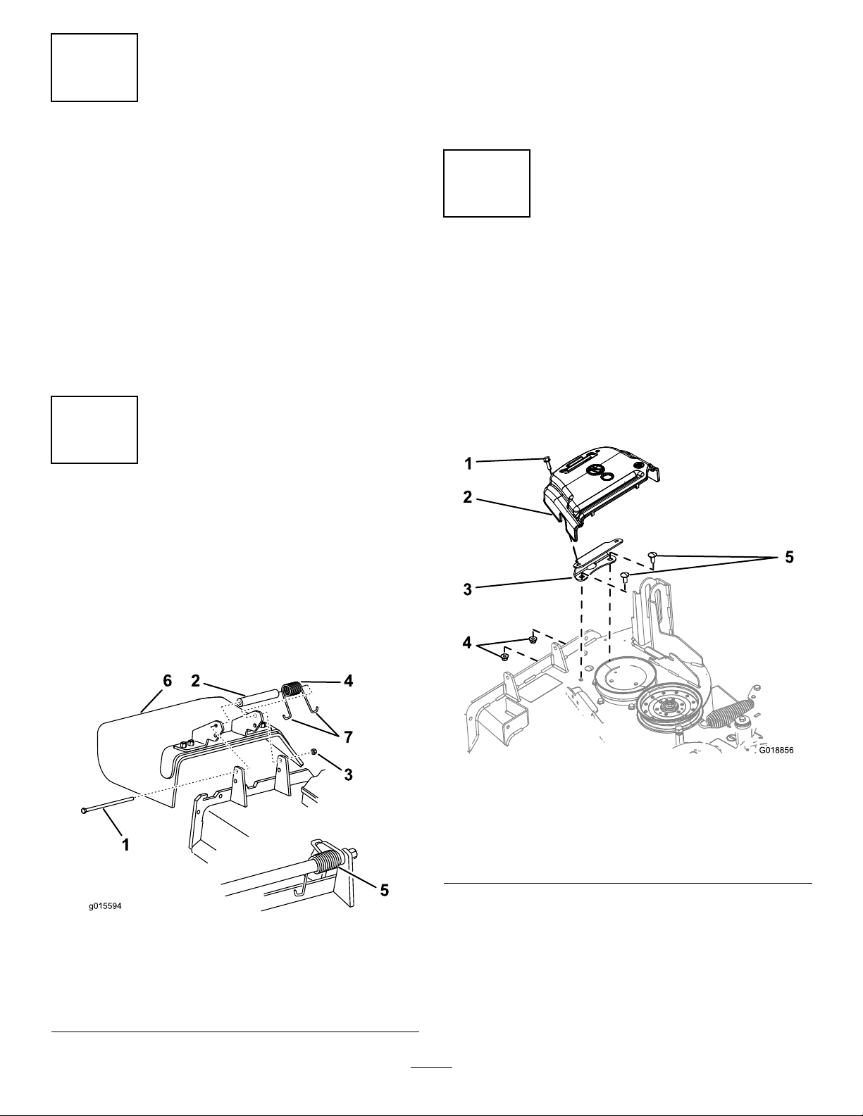
RemovetheBeltCover
Ifinstalled,removetheOEMbeltcoverasfollows:
1.Rotatetheboltthatsecuresthebeltcovertothe
counterclockwisetoloosenit(Figure2).
NoPartsRequired
RemovingtheDischargeChute
Important:Installtheside-dischargechutewhenyou
removethebaggerandblower.
1.Removethelocknut,bolt,spacer,andspringthatsecure
theside-dischargechutetothemowerdeck(
Figure1
1.Bolt
2.Spacer6.Side-dischargechute
3.Locknut
4.Spring
5.Springinstalled
7.J-hookendofspring
Figure1).
Figure2
1.Bolt(retainedtothebelt
cover)
2.Beltcover
3.Cover-mountingbracket
2.RemovetheOEMbeltcoverandboltfromthe
mountingbracket(Figure2).
Note:RetaintheOEMbeltcoverandboltforinstallation
whenoperatingthemowerwiththebloweraccessory
removed.
4.Flangenut(3/8inch)
5.Carriagebolt(3/8x7/8
inch)
2
Page 3
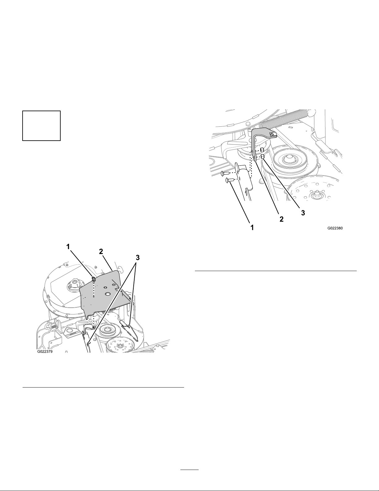
RemovetheCoverMountingBracket
1.Removethe2boltsand2angenutsthatsecurethe
covermountingbrackettothedeck(Figure2).
Note:Retainaangenutforinstallationofthe
CEkit;refertoInstallingtheCEPulleyGuardand
Belt-coverBracket(page4).
2.Removethebracket.
RemovetheBeltCoverBracket
Iftheblowerkitisinstalledonthemachine,removethe
beltcoverbracketinstalledfromthebloweranddrivekitas
follows:
1.Removethe2carriagebolts(1/4x3/4inch)and2
locknuts(1/4inch)thatsecuresthebeltcoverbracket
totheforwardangeofthemowerdeck(Figure2).
Note:RetaintheOEMcovermountingbracket,bolts,
andangenutforinstallationwhenoperatingthe
mowerwiththebloweraccessoryremoved.
4
RemovingtheBlowerKitParts (IfInstalled)
NoPartsRequired
RemovingtheBeltCoverfortheBlower
Iftheblowerkitisinstalledonthemachine,removethebelt
coverinstalledfrombloweranddrivekitasfollows:
1.Removethethumbscrewthatsecuresthebeltcover
(Figure3).
Note:Retain1carriageboltand2locknutsfor
installationwiththeCEKit;refertoInstallingthe
CEPulleyGuardandBelt-coverBracket(page4).
Figure4
1.Carriagebolt(1/4x3/4
inch)
2.Beltcoverbracket
3.Locknut
Figure3
1.Thumbscrew
2.Beltcover
2.Movethecoveroutwarduntiltheedgeofthecover
clearsthehooksinthedeckanges(Figure3).
3.Removethecoverfromthedeck.
Note:Discardthethumbscrew .
Note:Retainthebeltcoverforinstallationwith
theCEKit;referto8InstallingtheCEBeltCover
(page8)
.
3.Deckangehooks
2.Removethebeltcoverbracketfromthemowerdeck
(Figure2).
Note:Discardthebeltcoverbracket.
3
Page 4

RemovingtheOEMShaftCoverand
G018861
1
2
4
5
5
4
5
4
3
Hardware
1.Removethe3serratednutsthatsecuretheOEMshaft
covertotheblowerassembly(Figure5).
Note:Donotloosentheboltsandnutsthatsecure
theupper-bearinghousingthatarebeneaththeOEM
shaftcover.
Note:RetaintheserratednutsfortheCEshaft
guardinstallation;refertoInstallingtheCEShaft
Guard(page5).
5
InstallingtheCEPulleyGuard andBelt-coverBracket
Partsneededforthisprocedure:
1
CEpulleyguard
1
CEbelt-coverbracket
1
Carriagebolt(1/4x1)
1
Hex-headbolt(3/8x1inch)
1
Clipnut
InstallingtheCEPulleyGuardand
Belt-coverBracket
1.AligntheholesoftheCEpulleyguardtotheholein
theforwarddeectorbracketandtheoutboardholein
theforwarddeckange(Figure6).
Note:TheCEpulleybracketwrapsaroundthe
outboardedgeofthedeectorbracket
Figure5
BlowerShaftCoverandHardwareRemoval
1.Serratednut(5/16inch)4.Hex-headbolt(1/4x3/4
2.OEMshaftcover5.Locknut(1/4inch)
3.Boltandnut(upper
bearinghousing)
2.RemoveanddiscardtheOEMshaftcover(Figure5).
3.Removethe3hex-headbolts(1/4x3/4inch)and3
locknut(1/4inch)fromtheblowerhousingasshown
inFigure5.
Note:RetaintheboltsandnutsfortheCEguard
installation;refertoInstallingtheCEUpperGuards
(page5).
inch)
Figure6
1.CEpulleyguard7.Flangenut(3/8inch,OEM)
2.Locknut(1/4inch,blower
kit)
3.CEbelt-coverbracket9.Hex-headbolt(1/4x1
4.Hex-headbolt(3/8x1
inch,CEkit)
5.Deckhole
6.Clipnut
8.Deectorbracket(forward)
inch,CEkit)
10.Carriagebolt(1/4x3/4
inch,blowerkit)
11.Deckange(forward)
2.AligntheCEbelt-coverbrackettotheholesattherear
sideoftheforwarddeckange(Figure6).
4
Page 5

3.SecuretheCEpulleyguardandthebeltcoverbracket
G018858
1
2
4
5
6
6
7
4
4
3
totheforwarddeckangeattheoutboardholewiththe
carriagebolt(1/4x1inch,CEkit)andthelocknut(1/4
inch,blowerkit)thatyouremovedinstep1ofRemove
theBeltCoverBracket(page3);refertoFigure6.
4.Securethebeltcoverbrackettotheforwarddeckange
attheinboardholewiththeacarriagebolt(1/4x3/4
inch,blowerkit)andthelocknut(1/4inch,blowerkit)
thatyouremovedinstep1ofRemovetheBeltCover
Bracket(page3);refertoFigure6.
5.AligntheholeintherearangeoftheCEbelt-cover
bracketwiththeholeinthedeckwhereyouremoved
theOEMbeltcoverbracketinstep1ofRemovethe
CoverMountingBracket(page3);refertoFigure6.
6.SecuretherearangeoftheCEbelt-coverbracketto
thedeckwithahex-headbolt(3/8x1inch)andthe
angenut(3/8inch)thatyouremovedinstep1of
RemovetheCoverMountingBracket(page3);refer
Figure6.
to
7.AligntheclipnutwiththeholeinthetopoftheCE
belt-coverbracket,andpushtheclipnutontothe
bracket(Figure6).
Figure7
1.Serratednut(5/16inch)5.CEforwardguard
2.CEshaftguard6.Locknut(1/4inch)
3.Boltandnut(upper
bearinghousing)
4.Hex-headbolt(1/4x3/4
inch)
7.CEtensionerguard
6
InstallingtheCEUpperGuards
Partsneededforthisprocedure:
1
CEshaftguard
1
CEforwardguard
1
CEtensionerguard
InstallingtheCEShaftGuard
1.AligntheCEshaftguardtothe3boltsand3nutsthat
securetheupper-bearinghousing(Figure7).
2.SecuretheCEshaftguardtotheblowerwiththe3
serratednutsthatyouremovedinstep1ofRemoving
theOEMShaftCoverandHardware(page4);refer
to(Figure7).
InstallingtheCEUpperGuards
1.AligntheCEforwardguardtotheupperblower
housing(Figure7).
2.SecuretheCEforwardguardtotheupperblower
housingwithahex-headbolt(1/4x3/4inch)and
alocknut(1/4inch)thatyouremovedinstep3of
RemovingtheOEMShaftCoverandHardware(page
4);refertoFigure7).
3.AligntheCEtensionerguardtotheupperblower
housing(Figure7).
4.SecuretheCEtensionerguardtotheupperblower
housingwith2hex-headbolt(1/4x3/4inch)and
2locknut(1/4inch)thatyouremovedinstep
RemovingtheOEMShaftCoverandHardware(page
4);refertoFigure7.
3of
5
Page 6

7
G018367
1
2
3
2
4
6
5
7
7
InstallingtheCELowerGuard
Partsneededforthisprocedure:
1
CElowerguard
2
Hex-headbolt(1/4x3/4inch)
2
Washer(1/4x5/8)
2
Locknut(1/4inch)
RemovetheBlower
Ifinstalledremovetheblowerassemblyfromthemower
deckasfollows:
1.Pullthespringloadedidlerpulleyawayfromthexed
springpost,andremovethebeltfromtheidlerpulley
(Figure8).
2.Movetheidlerpivotbrackettowardthexedspring
post.removethehookofthespringfromtheidler
springpost(Figure8).
3.Routethebeltbeneaththeidlerpulley(Figure9).
Figure8
1.Latchpin(lockingposition)6.Belt(alignedtotheidler
2.Chutebracket
3.Blowerassembly
4.Springhookends
5.Idlerpivotbracket
pulley)
7.Idlerspringpost
8.Spring
9.Fixedspringpost
Figure9
1.Drivepulley
2.Blowerbelt
3.Blowerpulley7.Mowerdeck
4.Idler/tensionpulley
5.Blower(housing
repositionedforillustrative
purposes)
6.Blowerinposition(housing
portionremovedfor
illustrativepurposes)
4.Removethebeltfromdrivepulley(Figure9).
5.Movetheblowerlatchpintotheopenpositionand
swingthebloweroutward(Figure8).
6.Removetheblowerandbeltfromthemowerdeck.
6
Page 7

DrillingtheMountingHolesfortheCE
11
9
10
5
1
2
3
4
98
6
7
10
G018859
LowerGuard
1.AlignthelowerCElowerguardtotheblower-chute
bracketasshowninFigure10.
InstallingtheCELowerGuard
Note:InstalltheCElowerguardwiththeblowerassembly
removedfromthemowerdeck;refertothe48inE-ZV ac™
BlowerandDriveKitInstallationInstructions.
1.AligntheCElowerguardtotheblower-chutebracket
(Figure10).
2.Alignhole2andhole4oftheCElowerguardto
therivettailsprotrudingthroughtheblower-chute
bracket(
Figure10).
3.SecuretheCElowerguardtotheblowerwith2
hex-headbolt(1/4x3/4inch),2washers,and2
locknut(1/4inch)throughhole1andhole4ofthe
CEguard(Figure10).
InstallingtheBlower
IfyouremovedtheblowerinRemovetheBlower(page6),
installtheblowerassemblytothemowerdeckasfollows:
Note:Refertothe48in,52in,and60inE-ZV ac™TwinSoft
BaggerOwner’ sManual.
Figure10
1.Hole1
2.Hole2
3.Hole39.Rivettails
4.Hole410.Blower-chutebracket
5.CElowerguard11.Drillbit7mm(0.277inch)
6.Washer
7.Hex-headbolt(1/4x3/4
inch)
8.Locknut(1/4inch)
2.Alignhole2andhole4ofthelowerCElowerguard
totherivettailsprotrudingthroughtheblower-chute
bracket(
Figure10).
Note:EnsurethattheangeoftheCElower
guard(theangewiththeholes)isatagainstthe
blower-chutebracket.
3.Marktheoutlineofhole1andhole3oftheCElower
guardontheblower-chutebracket,andremovetheCE
guard(Figure10).
4.Locatethemarksontheblower-chutebracket,and
center-punchthelocations.
1.Aligntheblowerbeltaroundthepulleyoftheblower
(Figure9).
2.Alignthepivotpinontheblowerwiththepivotpin
holeinthedeckandlowertheblowerontodeck.
3.Opentheblowerlatchpin,closetheblowertothedeck,
andsecurethelatchpintothechutebracket(Figure8).
Note:Ensurethatthelatchpinextendsthroughthe
holeinchutebracketandtheCEpulleyguard.
4.Temporarilyroutethebeltbeneaththeidlerpulley
(Figure9).
5.Routethebeltaroundthedrivepulley(Figure9).
6.Movetheidler/tensionpulleytowardthexedspring
post,andinstallthespringbyaligningthespringhook
ontotheidlerspringpost(Figure8).
7.Pullthespringloadedidler/tensionpulleyawayfrom
thexedspringpost,androutethebeltaroundthe
idlerpulley(
Figure9).
5.Drill7mm(0.277inch)holesintheblower-chute
bracketatthe2center-punchmarks(Figure10).
7
Page 8

8
G018860
1
2
3
4
5
6
7
6
8
InstallingtheCEBeltCover
2.Inserttheboltandwasherthroughtheholeinthetop
ofthebeltcoverfromtheOEMbloweranddrivekit
(Figure11).
3.Fromthebottomofthebeltcover,assemblethe
washer(1/4x1/2inch)andretaineroverthehex-head
boltthreads(Figure11).
Partsneededforthisprocedure:
1
Hex-headbolt(1/4x3/4inch)
1
Washer(5/16x3/4inch)
1
Washer(1/4x1/2inch)
1Retainer
InstallingtheCEBeltCoverBolt
1.Assemblethewasher(5/16x3/4inch)tothehex-head
bolt(1/4x3/4inch)asshowninFigure11.
Ensurethattheboltheadandwasherarepositioned
ushwiththeuppersurfaceofthebeltcoverandthe
washerandretainerareushwiththebottomsurface
ofthecover.
InstallingtheBeltCover
1.Unlatchtheblowerandpullitoutpartially.
2.Alignthebeltcoverwithnotchesinthedeckanges
(Figure11).
3.Alignthehex-headboltinthecoverwiththeclipnut
onthebelt-coverbracket.
4.Securethebeltcovertothecoverbracketwiththe
hex-headbolt(Figure11).
5.Opentheblowerlatchpin,closetheblowertothe
deck,andsecurethelatchpintothechutebracket.
Figure11
1.Hex-headbolt(1/4x3/4
inch)
2.Washer(5/16x3/4inch)
3.Beltcover
4.Washer(1/4x1/2inch)8.Clipnut
5.Retainer
6.Deckbracketnotch
7.CEbelt-coverbracket
8
 Loading...