

Page 1
SpeedControlLinkageKit
2009GrandStand
ModelNo.119-8770
LooseParts
Usethechartbelowtoverifythatallpartshavebeenshipped.
FormNo.3366-810RevC
®
Mower
InstallationInstructions
ProcedureDescription
1
2
3
4
5
Qty.
Nopartsrequired
Nopartsrequired
ObtainpartsfromanAuthorizedService
Dealer
Hairpincotterpin2
Flatwasher4
Speedcontrollinkage
Shoulderhub
Flangenut(1/4inch)
Bolt(1/4x1-3/8inch)
Rodendballjoint2
Rollerbushing8
Bolt(1/4x2-3/4inch)
Controlfork
Upperswitchlever1
Plasticcabletie1
Plasticcabletie1Adjustthespeedcontrol.
–
–
2Replacethepumparm.
2
2
4
2
2
2
Preparethemower.
Removetheexistingcontrols.
Installthenewcontrols.
Use
1
PreparingtheMower
NoPartsRequired
Procedure
1.Allowthemachinetocooldownbeforeinstalling
thiskit.
2.Thoroughlycleanthemachine.Alldebrismustbe
removedtoensurethekitwilltproperly .
3.Repairallbentordamagedareasandreplaceany
missingparts.
©2010—TheToro®Company
8111LyndaleAvenueSouth
Bloomington,MN55420
Registeratwww.T oro.com.
2
RemovingtheExisting
Controls
NoPartsRequired
Procedure
1.Releasethecushionforrearaccess.
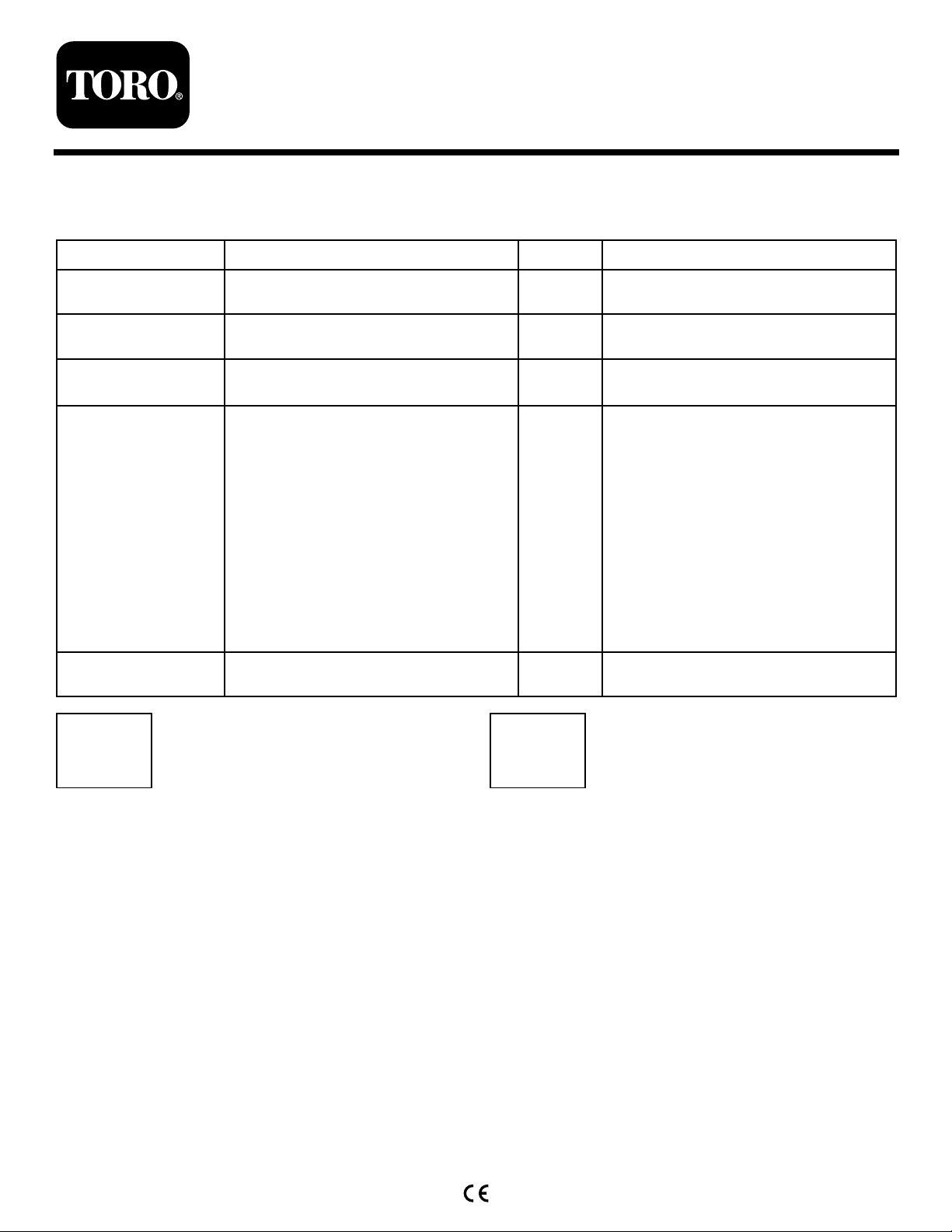
2.Frombehindtheengine,removethehairpincotter
pinfromtheexistingcontrollinkageandfront
bracket(Figure1).
OriginalInstructions(EN)
PrintedintheUSA.
AllRightsReserved
Page 2
G013702
1
2
3
Figure1
1
2
G013701
3
4
1.Engine3.Hairpincotterpin
2.Existingcontrollinkage
3.Removethehairpincotterpinandwasherfromthe
existingcontrollinkage.Removetheexistingcontrol
linkagefromtheforksandpumparm(
Figure2).
4.Removethecableendfromthefork(Figure2).
5.Removethecableendfromthecable(Figure2).
6.Removethebolt,nut,spacerandwashersfrom
theforkandtheupperandlowerswitchbrackets
Figure2).
(
Figure2
1.Existingcontrollinkage
2.Hairpincotterpin4.Rightcableend
3.Boltandnutinforkand
controlarm
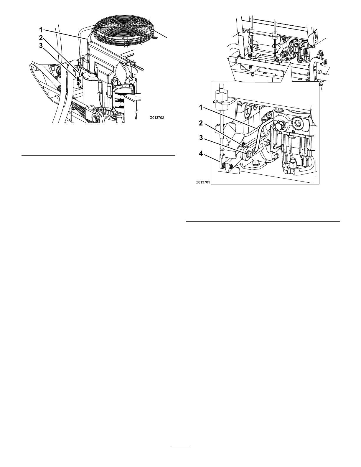
7.Loosenthecableclampsecuringthespeedcontrol
cablejackettotheshifterbracket(Figure3).Itis
easiesttoaccessthisunderthelowerframeandin
frontoftheleftrearwheel.
2
Page 3
1
2 3
4
G013763
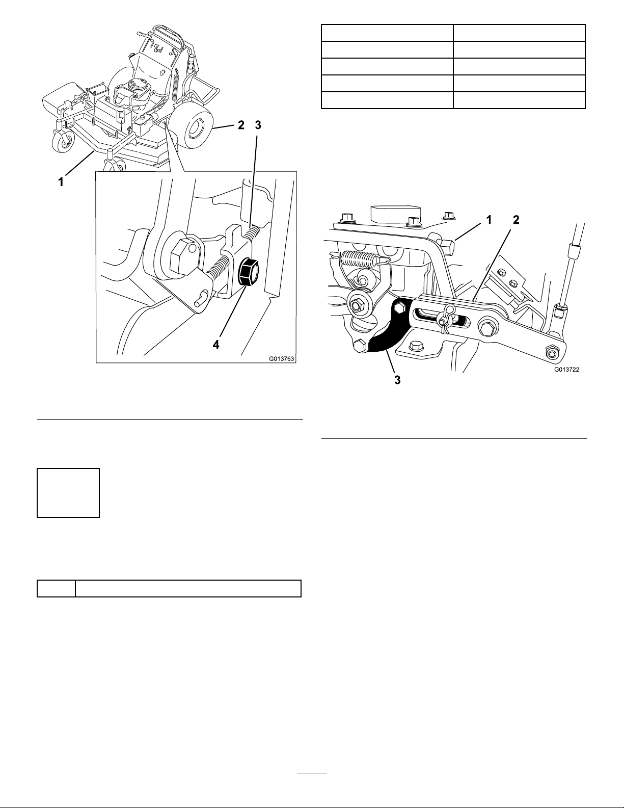
ModelNumber
G013722
1 2
3
74558290000209andbelow
74559290000156andbelow
74568290000205andbelow
74569290000206andbelow
SerialNumber
1.Removethetwonutsandboltsattachedtothepump
arm(Figure4).Savethishardware.
2.Removethepumparmfromthefork(Figure4).
3.Installthenewpumparmwiththeexistinghardware
previouslyremoved.
Figure3
1.Mowerdeck
2.Leftreartire4.Cableclamp
3.Speedcontrolcable
8.Performthissameprocedurefortheopposite
control.
3
ReplacingthePumpArm
Partsneededforthisprocedure:
2
ObtainpartsfromanAuthorizedServiceDealer
Procedure
Note:Thisprocedureisonlyforcertainmodelsof
Grandstandmowerswiththeserialnumberslisted.
1.Lefthandpumpshown
2.Fork
Figure4
3.Pumparm
Pumparmsarenotincludedinthiskit.Contactan
AuthorizedServiceDealerforthepumparms.
Thefollowingtableliststhemachinesthatneedthe
pumparmsreplaced.
3
Page 4

ensurestheforkandcablewilltravelwithoutbinding
Figure5).
(
4
InstallingtheNewControls
Partsneededforthisprocedure:
2Hairpincotterpin
4Flatwasher
2
Speedcontrollinkage
2
Shoulderhub
4
Flangenut(1/4inch)
2
Bolt(1/4x1-3/8inch)
2Rodendballjoint
8Rollerbushing
2
Bolt(1/4x2-3/4inch)
2
Controlfork
1Upperswitchlever
1Plasticcabletie
9.Tightentheexistingjamnutontherodendball
joint.Makesurethecabledoesnothaveatwistinit.
Procedure
1.Positionthenewforkwiththepumparminbetween
thefork.
2.Installthenewupperswitchleverandexisting
lowerswitchleverontothelefthandshoulderhub
Figure5).
(
3.Installtheforktotherearbracketwithanewbolt
(1/4x2-3/4inch),washer,shoulderhubanda
angenut(1/4inch)(Figure5andFigure6).Do
nottightenatthistime.
4.Installthenewspeedcontrollinkagetotheforkwith
3rollerbushings,aatwasherandahairpincotter
Figure5).
pin(
5.Frombehindtheengine,installthespeedcontrol
linkagetothefrontbracketwithaatwasheranda
hairpincotterpin(Figure5andFigure6).
6.Threadtherodendballjointallthewayontothe
endofthecableandthenbackitoff2turns.DO
NOTtightenthejamnutatthistime.
Note:Ensuretheballjointsareinstalledonthe
insideoftheforks(Figure6).
7.Installtherodendballjointtotheforkwithabolt
(1/4x1-3/8inch),rollerbushingandangenut
(1/4inch).
8.Holdtherodendballjointperpendiculartothe
boltwhentighteningtheangenutandbolt.This
4
Page 5

G014214
1 2
2 1
3
4
5
6
7
15
11 10 9
12 13 14
3
2 1 4
18
5 1 6 7 15 10 8 19 9 16 17
8 19
Figure5
1.Flatwasher
2.Hairpincotterpin7.Fork12.Newupperswitchlever17.Useexistinglowerswitch
3.Speedcontrollinkage
4.Rollerbushing
5.Bolt(1/4x2-3/4inch)10.Shoulderhub
6.Flangenut(1/4inch)
8.Rodendballjoint
9.Bolt(1/4x1-3/8inch)14.Correctpositionofrodend
11.Existinglargewasherused
onrightsideonly(shown
hereforillustrativepurposes)
13.Wrongpositionfortherod
endballjoint(topview)
balljoint(topview)
15.Rollerbushing
16.Donotremovetheexisting
switch
lever
18.Existingneutralstoparmon
leftsideonly
19.Existingjamnut(tighten
afterinstallingrodendball
joint)
5
Page 6

G013703
1
3 2
5 4
Figure6
G013818
1 2
G013764
1 2
1.Frontbracket4.Existinglargewasher
usedonrightsideonly
2.Pumpcontrolarm5.Existingneutralstoparm
onleftsideonly
3.Rearbracket
5
AdjustingtheSpeedControl
Partsneededforthisprocedure:
1Plasticcabletie
Procedure
1.SettheHOCleverto2inchesandmovethespeed
controllevertotheFASTposition.
2.Ensurethecableclampsecuringthespeedcontrol
cablejackettotheshifterbracketisloose(Figure10).
3.Loosentheboltthatgoesthroughthecenterofthe
lefthandshoulderhubandcontrolfork(Figure8).
4.Removethehairpincotterpinandwasherfromthe
endofthelefthandspeedcontrollinkageassembly
(Figure8).
10.Usingtheplastictie,fastenthespeedcontrolcable
totherightcontrolcable(Figure7).
1.Plasticcabletie
Figure7
2.Speedcontrolcable
11.Performthissameprocedurefortheopposite
control.
Figure8
1.Hairpincotterpinandat
washer
2.Loosenthisbolt
5.Infrontofthelefthandspeedcontrollinkagerollers,
inserta7/32ndinchallenwrenchintotheslotsof
thecontrolforkandcontrolarm(Figure9).
6.Pushthespeedcontrollinkageforward,andtighten
theclampsecuringthespeedcontrolcablejacketto
theshifterbracket(Figure9andFigure10).
6
Page 7

G013765
1 2
3
1.7/32ndinchallenwrench
1
2 3
4
G013763
5
G013767
1
2
4 3
2.Slots
Figure9
3.Pushthespeedcontrol
linkageforward
(Figure11).Donotforcetheneutralassembly
together.
Figure11
1.Plasticcabletie4.Neutralstoparm
2.Upperswitchlever
3.Lowerswitchlever
5.Switch(Donotremove)
1.Mowerdeck
2.Leftreartire4.Cableclamp
8.Whilepullingthecontrolforkassemblyrearward
(notsohardthatthespeedcontrollinkagemoves)
tightenthescrewthatgoesthroughthecenterofthe
lefthandshoulderhub(Figure12).
Note:Itisimportanttokeepthepumpcontrolarm
andcontrolforkslotsareinlinewitheachother.
Thiscanbeachievedbymakingsurethetopofthe
pumpcontrolarmandcontrolforkareparallelto
eachother.
Figure10
3.Speedcontrolcable
7.Theswitchstoparmmustbealignedwiththe
cableendofthecontrolfork.Usingacabletie,
securetheneutralassemblytoalignthecomponents
7
Page 8

G013768
1 3
2
Figure12
1.Movementofcontrolarm
2.Slotsarealigned
3.Tightenthisbolt
9.Removetheallenwrenchfromslotsofthecontrol
forkandcontrolarmslotsandcutthecabletiefrom
theneutralassembly.
10.Installthewasherandhairpintotheendofthe
speedcontrollinkage.
11.Repeatsteps3through10(donotdostep7)onthe
righthandside.
8
 Loading...