

Page 1
KawasakiEngineConversionKit,Suzuki-Powered
Heavy-DutyLawnMowerswithZoneStart
ModelNo.119-7844
Installation
LooseParts
Usethechartbelowtoverifythatallpartshavebeenshipped.
FormNo.3365-741RevA
InstallationInstructions
ProcedureDescription
2
1
Beltcover(74-1770)
Engine(117-5220)
Decal(110-0520)
Screw(95-1727)
Bladeretainerspacer(103-3795)
Tankbracket(115-0954-03)
Fueltankcap(93-7198)
Screw(104-2628)
Fuelhose(109-0296)
Fuellter(71-9280)
Clamp(2412-98)
Fuelhose(109-0650)
Cabletie(3290-378)
Bladebolt1
BBCspacer
Springwasher
Throttlecontrol(1 17-3543)
6.Removethebeltfromthedriverpulley;inspectthe
beltforwearandreplaceitifnecessary.
7.Removetheenginemountingbolts.
Qty.
Use
1
1
1
4
1
1
1
3
1
1
4
1
4
1
2
1
Installthenewengine.
RemovingtheOldEngine
NoPartsRequired
Procedure
Important:Saveallfastenersthatyouremovedfor
reuseunlessotherwisenoted.
1.Drainthefuelfromthefueltank.
2.Removetheoldbeltcoveranddiscardit.
3.Removeanddiscardthethrottlecontrolcable.
4.Removeanddiscardtheoldfuelhose,fuellter,
andclamp.
5.RemovethebladeandtheBBCassembly .
©2010—TheToro®Company
8111LyndaleA venueSouth
Bloomington,MN55420
Registeratwww.T oro.com.
8.Removetheoldenginefromthemowerhousing.
9.Removethefueltankfromthetankbaseandretain
itforreuse.
10.Replacethefueltankcapwithanewcapprovidedin
thekit;discardtheoldfueltankcap.
11.Removeanddiscardthedischargetunneldoor.
12.Cleanthemowerhousingandcheckitfordamage
andwear.
OriginalInstructions(EN)
PrintedintheUSA
AllRightsReserved
Page 2
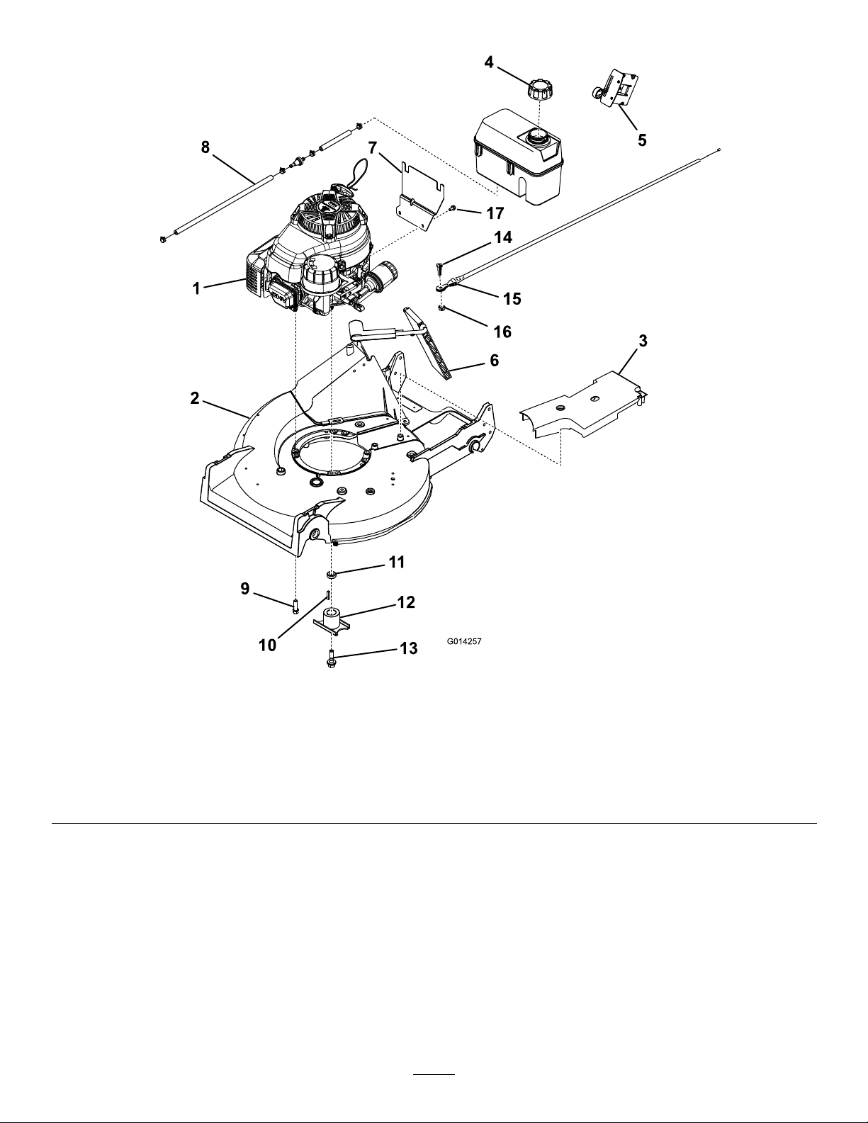
Figure1
1.Engine
2.Mowerdeck
3.Beltcover
4.Fueltankcap
5.Throttlecontrol12.Bladebolt
6.Dischargedoor13.Tankbracketscrew
7.Tankbracket
8.Fuelhose,fuellter,andclamps
9.Enginemountingbolt(4)
10.Spacer
11.Springwasher
2
Page 3

7.Attachthenewfuelhose,fuellter,andclamptothe
engineandthefueltank.
2
Partsneededforthisprocedure:
1
Beltcover(74-1770)
1
Engine(1 17-5220)
1
Decal(110-0520)
4
Screw(95-1727)
1
Bladeretainerspacer(103-3795)
1
Tankbracket(1 15-0954-03)
1
Fueltankcap(93-7198)
3
Screw(104-2628)
1
Fuelhose(109-0296)
1
Fuellter(71-9280)
4
Clamp(2412-98)
1
Fuelhose(109-0650)
4
Cabletie(3290-378)
1Bladebolt
1
BBCspacer
2
Springwasher
1
Throttlecontrol(117-3543)
Note:Theshorthoseattachestothefueltank.
8.Installandadjustthenewthrottlecontrolcable.
9.Replacethebeltcover.
Procedure
Note:RefertoFigure1forinstallingthenewengine.
1.Installthenewdooronthedischargetunnel.
2.Installthetankbracketontotheengineusing3
screws(fromtheloosepartsbag)andLoctite(242).
Note:Torquethescrewsto70–120in-lb.
3.Installthefueltankontothemountingbracketusing
2screws.
Note:Torquethescrewsto40–50in-lb.
4.Installthenewengineonthemowerhousing.
Note:Torquetheenginemountingboltsto
250–400in-lb.
5.InstalltheBBCassembly.
Note:ForinformationoninstallingtheBBC
assembly,refertotheWalkBehindPowerMowerDrive
SystemsServiceManual(FormNo.492-4733).
6.Installtheblade.
Note:T orquethebladenutsto180–320in-lb.
3
Page 4

 Loading...