

Toro 119-3454 Installation Instructions
BaggerFinishingKit
TITANZX6000SeriesZero-Turn-RadiusRidingMower
ModelNo.119-3454
ThiskitrequirestheBaggerKittocompleteinstallation.Contact
yourAuthorizedServiceDealerorthemanufacturerCustomer
Servicetoobtainthenecessaryparts.Formoreinformation,visitus
atwww.Toro.com.
Safety
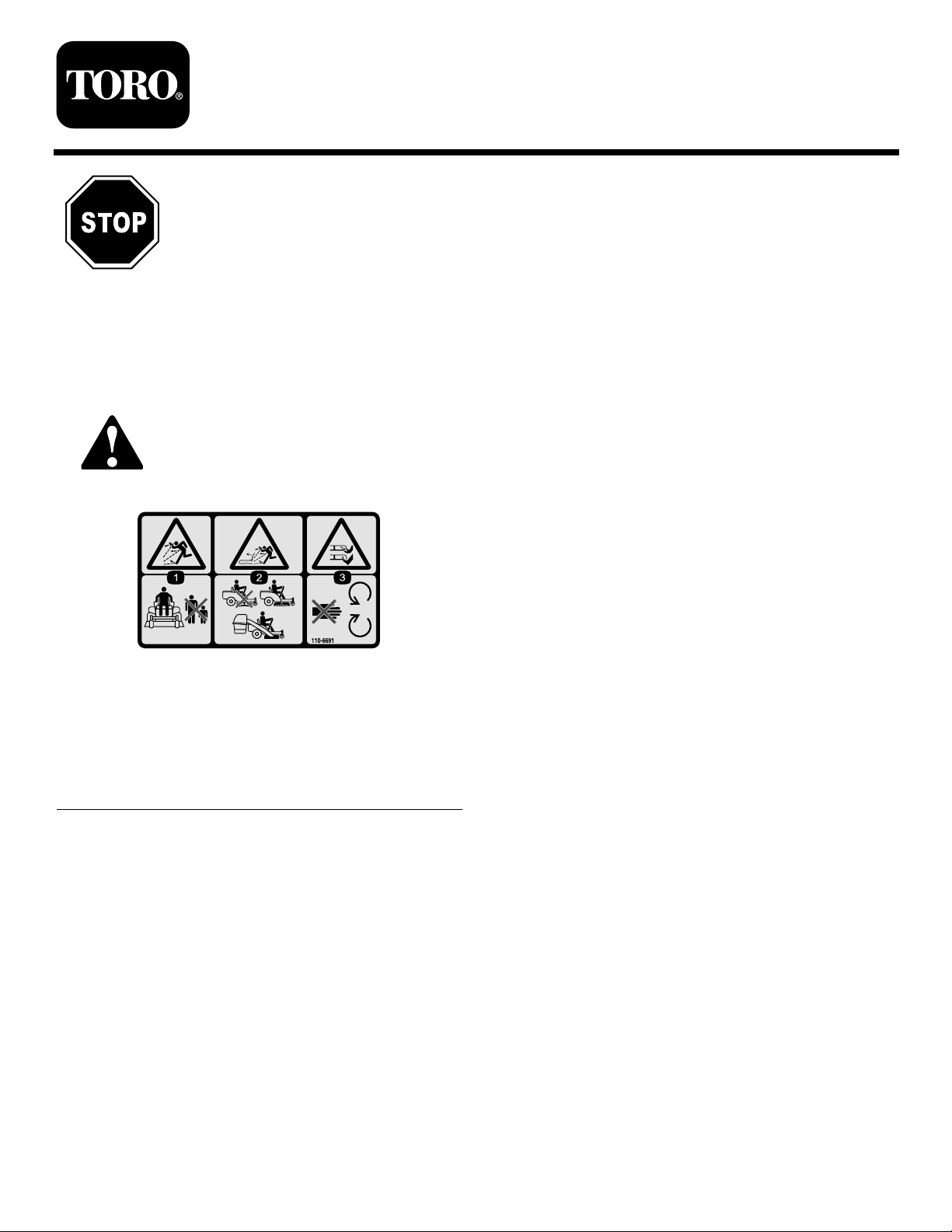
SafetyandInstructionalDecals
Safetydecalsandinstructionsareeasilyvisibletotheoperatorandarelocatednearanyareaof
potentialdanger.Replaceanydecalthatisdamagedorlost.
FormNo.3365-178RevA
InstallationInstructions
110-6691
1.Thrownobjecthazard—keepbystandersasafedistance
fromthemachine.
2.Thrownobjecthazard,mower—donotoperatewithoutthe
deector,dischargecover,orgrasscollectionsystemin
place.
3.Cutting/dismembermentofhandorfoot—stayawayfrom
movingparts.
©2010—TheT oro®Company
8111LyndaleA venueSouth
Bloomington,MN55420
Registeratwww.Toro.com.
OriginalInstructions(EN)
PrintedintheUSA.
AllRightsReserved
Installation
3
1
InstallingtheBaggerFrame
Partsneededforthisprocedure:
1
Baggerframeassembly(60inchdeck)
Procedure
ThisBaggerFinishingKitcontainsanewBaggerFrame
Assemblywhichisusedforunitswith60inchdecks
only.TheBaggerKitcomeswithaBaggerFrame
Assemblythatshouldbediscardedandreplacedwith
theoneincludedwiththisBaggerFinishingKit.
RefertotheBaggerKitinstallationinstructionsforthe
proceduretoinstallthebaggerframeassembly .
2
InstallingtheBlades
InstallingtheChute
Partsneededforthisprocedure:
1
Angledcutoffbafe
1
Curvedbafe
2
Locknut(5/16inch)
1Handknob
1Washer
1
Chute
Procedure
WARNING
Anuncovereddischargeopeningcouldallowthe
lawnmowertothrowobjectsintheoperatoror
bystander’sdirectionandresultinseriousinjury.
Also,contactwiththebladecouldoccur.
Neveroperatethelawnmowerunlessyouinstall
acoverplate,amulchplate,oragrasschuteand
catcher.
Partsneededforthisprocedure:
3
Hi-Liftblade
Procedure
1.Removetheexistingmowerbladesinstalledonyour
deck.RefertotheRemovingtheBladessectionin
theOperator’sManualformoreinformation.
2.InstalltheHi-Liftmowerbladeslocatedinloose
parts.RefertotheInstallingtheBladessectioninthe
Operator’sManualformoreinformation.
Neveroperatethemowerwiththedischargeopening
uncovered.Adischargecover,mulchcoverorbagging
chutemustalwaysbeusedwhenthemowerdeckis
operated.
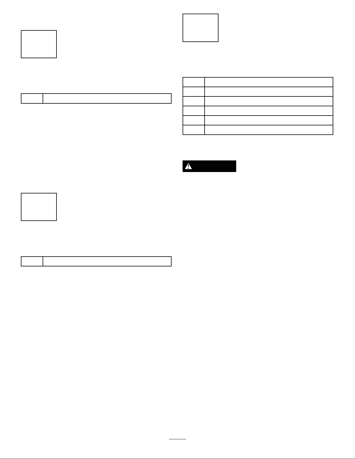
1.Removefastenerssecuringthedeectorassemblyto
thedeck(
Figure1).Retainallfasteners.
2

G013095
1
2
3
4
5
Figure1
G013096
1
2
3
4
5
6
7
8
9
10
G013097
1
2
3
4
5
6
1.Deectorassembly4.Carriagebolt(existing),
reuse
2.Locknut(existing),retain5.Carriagebolt(existing),
retain
3.Locknut(existing),reuse
2.Removethedeectorassembly.Retainallpartsto
convertthedecktosidedischarge.
frontwallofthemowerdeck.Securehorizontalpost
tothefrontwallofthedeckusingalocknut.
5.Installthechutetothedeck.Makesuretheopening
intopofthechutealignswiththeexposedposton
thedecktopandtheforwardverticalplatemates
withthefoldedmetalbracketofthechute.
3.Locateandinstalltheangledcutoffbafetothe
deckattherearholesinthemowerdeck.Usethe
existingfastenersfromthatlocationtosecurethe
angledcutoffbafetothedeck.
Figure3
1.Dischargechute4.Foldedmetalbracket,
2.Handknob5.Forwardverticalplate,
3.Washer6.Exposedpostinthedeck,
6.Installawasherandhandknoboverthepostcoming
throughthechutetop.Handtightentosecurethe
chutetothedeck.
chute
deck
curvedbafe
7.Hooktheexiblelatchonthechutetotheretaining
1.Holeinfrontwallofthe
deck
2.Locknut
3.Horizontalpost,curved
bafe
4.Verticalpost,curvedbafe9.Locknut(existing),reuse
5.Curvedbafe10.Center,forwardholein
Figure2
6.Highliftblade
7.Carriagebolt(existing),
reuse
8.Angledcutoffbafe
mowerdeck
claspweldedtothesidewallofthedeck.
4.Installthecurvedbafetodeck.Alignthevertical
postinthecurvedbafewithcenter,forwardholein
thedeckandthehorizontalpostwiththeholeinthe
3
 Loading...