

Page 1
FormNo.3365-252RevA
Operator-ControlledDischargeChuteKitwithBag
GrandStand
ModelNo.117-8565
®
Mowerwith36-inchor40-inchCuttingUnit
InstallationInstructions
Note:Determinetheleftandrightsidesofthemachine
fromthenormaloperatingposition.
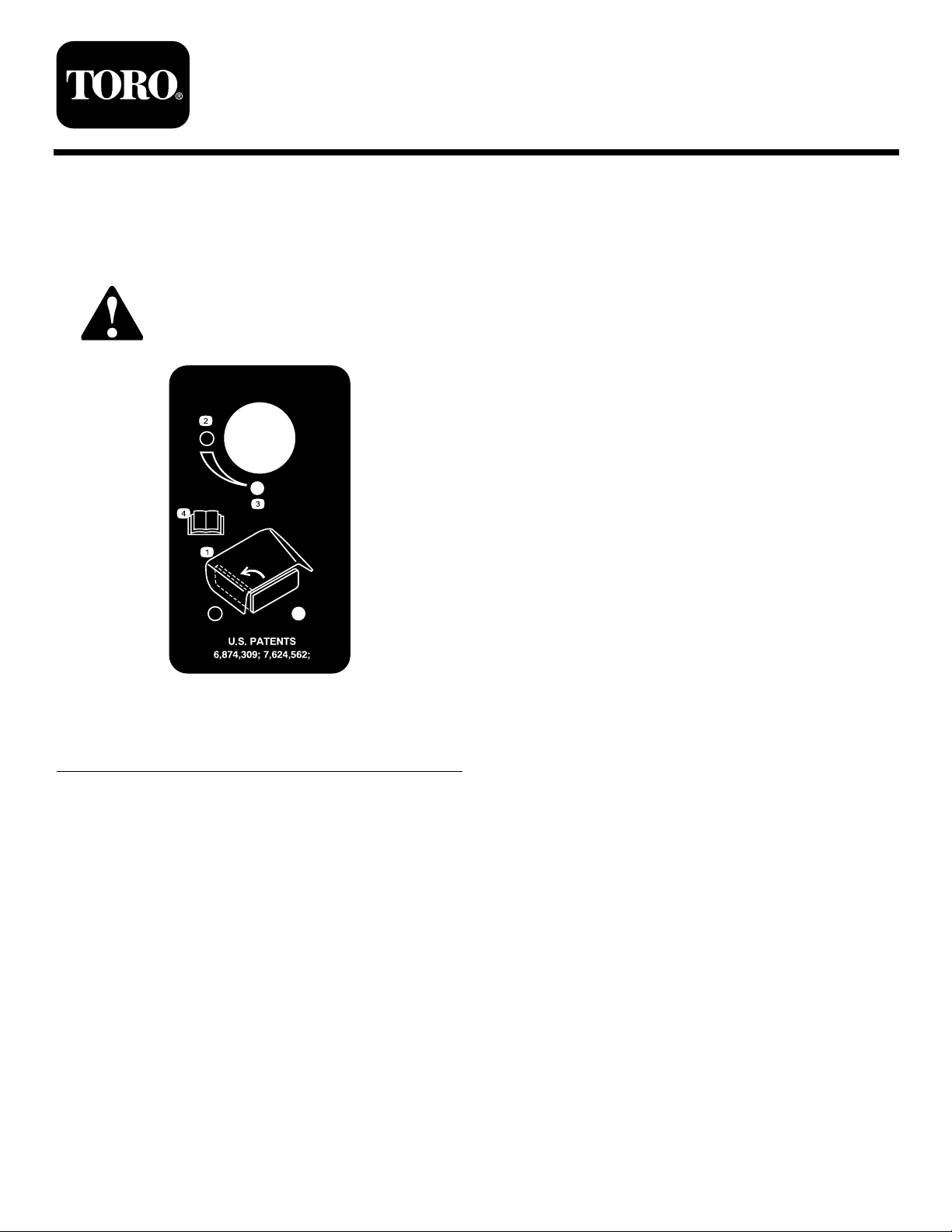
SafetyandInstructionalDecals
Safetydecalsandinstructionsareeasilyvisibletotheoperatorandarelocatednearanyareaof
potentialdanger.Replaceanydecalthatisdamagedorlost.
Safety
117-8569
1.Operatordischargecontrol3.Closed
2.Open4.ReadtheOperator’s
Manual.
©2010—TheT oro®Company
8111LyndaleAvenueSouth
Bloomington,MN55420
Registeratwww.Toro.com.
OriginalInstructions(EN)
PrintedintheUSA.
AllRightsReserved
Page 2
Installation
g012749
LooseParts
Usethechartbelowtoverifythatallpartshavebeenshipped.
ProcedureDescription
1
2
3
4
5
1
Qty.
Nopartsrequired
Sidedischargechute
Bolt,(5/16x7–1/2inches)
Locknut,(5/16inch)
Plasticspacer1
Spring
Nopartsrequired
Handleassembly1
Bolt,(3/8x1inch)(Selftapping)
Plasticcabletie2
Plasticmountwithadhesive2
Locknut1
Trashbag1Installthetrashbag.
–
1
1
1
1
–
2
Removetheexistingsidedischarge
chute.
Installthesidedischargechutewith
gate.
Drilltheholes.
Installthehandleandcables.
Use
RemovingtheExistingSide
DischargeChute
NoPartsRequired
Procedure
1.DisengagethePTO ,settheparkingbrake,andchock
orblockthedrivewheels.
2.Turnofftheengine,removethekey,andwaitforall
movingpartstostopbeforeleavingtheoperating
position.
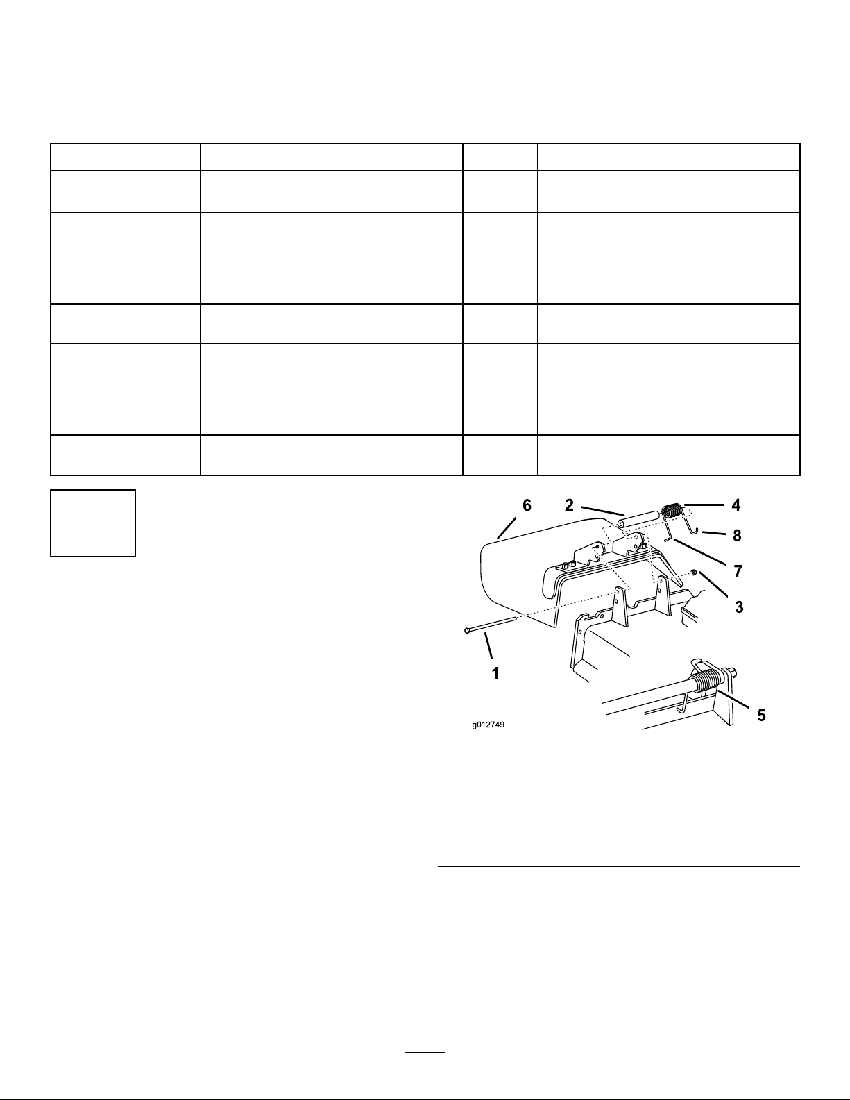
3.Removethelocknut,bolt,springandspacerholding
thedeectortothepivotbrackets(
Removethegrassdeector.
Figure1).
Figure1
1.Bolt
2.Spacer6.GrassDeector
3.Locknut
4.Spring8.Jhookendofspring
5.Springinstalled
7.Lendofspring,place
behinddeckedgebefore
installingbolt
2
Page 3
2
InstallingtheSideDischarge
ChutewithGate
Partsneededforthisprocedure:
1
Sidedischargechute
1
Bolt,(5/16x7–1/2inches)
1
Locknut,(5/16inch)
1Plasticspacer
1
Spring
Procedure
WARNING
Anuncovereddischargeopeningcouldallowthe
lawnmowertothrowobjectsintheoperator’sor
bystander’sdirectionandresultinseriousinjury.
Also,contactwiththebladecouldoccur.
•Neveroperatethelawnmowerunlessyouinstall
acoverplate,amulchplate,oragrasschuteand
catcher.
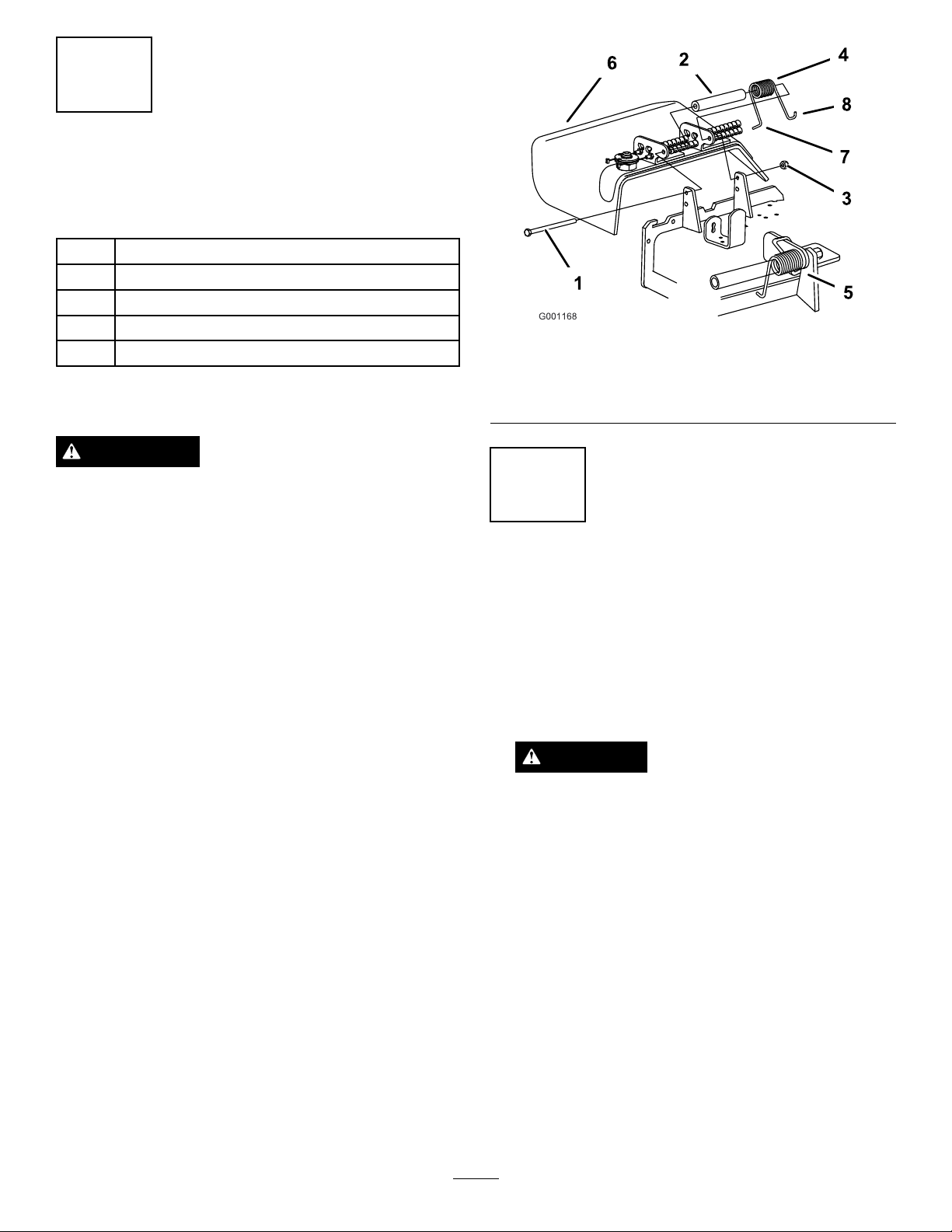
Figure2
1.Bolt
2.Spacer5.Springinstalled
3.Locknut
3
DrillingtheHoles
NoPartsRequired
4.Spring
6.GrassDeector
•Makesurethegrassdeectorisinthedown
position.
Note:Ensurethegrassdeectorisinstalledinthe
lowerholesinthemowerdeckbrackets.
1.Placethenewspacerandspringontograssdeector.
Placeoneendofspringbehinddeckedge.
Note:Makesuretheendofthespringisinstalled
behindthedeckedgebeforeinstallingtheboltas
shownin
2.Installboltandnutinthelowerhole.Placetheend
ofthespringaroundthegrassdeector(Figure2).
3.Tightenthenutuntiltheendoftheboltisushwith
theendofthenut.Donotovertighten.
Important:Thegrassdeectormustbeableto
lowerdownintoposition.Liftthedeectorup
totestthatitlowersintothefulldownposition.
Figure2.
Procedure
1.Beforedrillingtheholes,checkiftheholesalready
exist(Figure5).Proceedtoprocedure4iftheholes
exist.
DANGER
Incertainconditions,gasolineisextremely
ammableandhighlyexplosive.Areor
explosionfromgasolinecanburnyouandothers
andcandamageproperty.
•Placeapieceofmetalbetweenthefuel
tankandtheleftsideofthemachinebefore
drillingtheholes.
•Neverdrillintothesideofthefueltank.
•Afueltankleakmayresultinareor
explosionfromgasoline.
2.Placeapieceofmetalbetweenthefueltankandthe
leftsideofthemachine.Thiswillpreventthedrill
bitfromdrillingintothefueltank(Figure3).
3
Page 4
g013384
1
2
3
Figure3
g013370
1
2
g013370
1
2
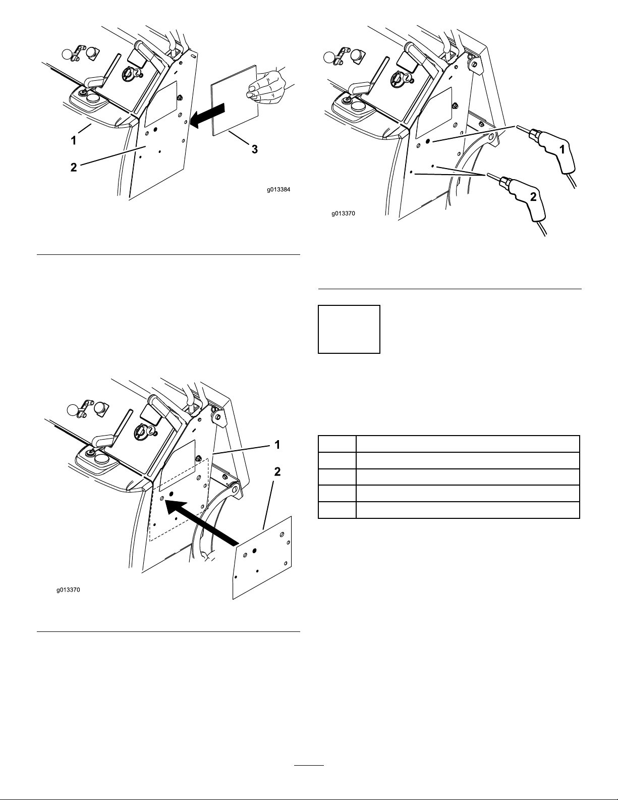
1.Fueltank
2.Leftsideofmachine
3.Steelplate
3.Locatethepapertemplateatthebackofthis
instructionsheetandcutitout.
4.Locatethetwoexistingholesandplacethetemplate
ontheleftsideofthemachine(
Figure4).
1.Drillone11/32inch
diameterhole
Figure5
2.Drilltwo11/64inch
diameterholes
5.Markthelocationfortheholes.Thesmallholesdo
notneedtobedrilledifthemanualtubeismounted
horizontaltotheground(Figure4).
Figure4
6.Drillone11/32inchdiameterholeintothesideof
themachineforthehandle(
Figure5).
7.Drilltwo11/64inchdiameterholesintothesideof
themachineforthemanualtube(Figure5).
4
InstallingtheHandleand
Cables
Partsneededforthisprocedure:
1Handleassembly
2
Bolt,(3/8x1inch)(Selftapping)
2Plasticcabletie
2Plasticmountwithadhesive
1Locknut
Procedure
Note:Determinetheleftandrightsidesofthemachine
fromthenormaloperatingposition.
1.Installthehandleassemblytotheleftsideofthe
machinewith2bolts(3/8x1inch)(Figure6).The
boltsarethreadformingbolts.Theholesdonot
requiretapping.
4
Page 5

g013358
3 2 1
Figure6
g013406
1 2 3
g013361
4
5
1
2
3
2
4
6
1.Bolt,(3/8x1inch)(self
tapping)
2.Handleassembly
3.Leftsideofmachine
2.Routethecablesthroughtherectangularopening
ontheleftsideoftheenginebaseandbetween
theenginebaseanddeckontherightsideofthe
machine(Figure7andFigure8).
3.Installanadhesivebackplasticmountontheverticle
partoftheframetubejustinfrontofthehydraulic
oillter.See
theplasticmountandsecurethecableswiththe
Figure8.Threadthecabletiethrough
cabletie.
4.Installanadhesivebackplasticmountonthetopof
themowerdeckontherightsidesothecablesdo
notcontacttheclutchorbeltdrive.See
Figure8.
Threadthecabletiethroughtheplasticmountand
securethecableswiththecabletie.
1.Rectangularopeningon
theleftsideoftheengine
base
2.Hydraulicoillter
Figure7
3.Cables
Figure8
1.Hydraulicoillter4.Cabletieandplastic
2.Cabletieandplastic
mountonsideofframe
3.Hydraulictank
mountontopofmower
deckontherightside
5.Cables
6.Leftsideofthemachine
5.Removethejamnutsfromthethreadendsofthe
cables(Figure10).
6.Locatethecablethatisattachedtotheoutsideof
thehandleassemblyandinstallthiscableintothe
outsideholeinthesidedischargechute(
Figure9).
5
Page 6

g013405
1
1
2
2
Figure9
g013403
1
2
3
4
5
g013404
1 2 3 4 5
1
3
4
5
1.Outsidecableinstalled
intotheoutsideholeinthe
sidedischargechute
2.Insidecableinstalledinto
theinsideholeintheside
dischargechute
7.Installthejamnutsandcablebarrelendthroughthe
largehole(
Figure10).
8.Installthecableintothesmallestdiameterholein
thesidedischargechute(Figure10).
Figure11
1.Outsidecable4.Threadedendofthecable
2.Jamnutthreaded1/2onto
cableend
3.Jamnut
5.Cableendbarrel
11.Whileholdingontothegateassembly,removethe
jamnutanddiscard(Figure12).
Figure10
1.Largehole4.Jamnuts
2.Smallhole5.Cableendbarrel
3.Threadedendofcable
9.Installonejamnutontothethreadedendofthe
cable½waydownthethreads(Figure11).
10.Installthecablethroughthesmallestdiameterhole
inthesidedischargechuteandinstalltheotherjam
nuttosecurethecable(Figure11).
6
Page 7

g013359
1
2
3
4
5
Figure12
g013385
1
2
3
4
5
1.Removejamnutand
discard
2.Washer5.Holdgatewhileremoving
3.Uppercableplate
12.Installthecableendbarrelsintothelowercableplate
4.Cableendbarrel
thejamnut
andsecurethemwiththeuppercableplate,awasher
andlocknut(Figure13)
Note:Makesurethecablesarenotpinchedbefore
tighteningthelocknut.
Figure13
1.Locknut
2.Washer5.Holdgatewhileinstalling
3.Uppercableplate
4.Cableendbarrelsinstalled
inlowercableplate
thelocknut(Makesurethe
cablesarenotpinched)
7
Page 8

g013358
2 1
Operation
5
InstallingtheTrashBag
Partsneededforthisprocedure:
1Trashbag
Procedure
Installthetrashbagintotheslotsinthehandleassembly
(Figure14).
UsingtheChuteGate
CAUTION
Thechutegatedoesnotsealthedischarge
opening.Grassandobjectsmaybethrownina
bystander’sdirectionandresultinseriousinjury.
•Beawareofthemowerdischargedirectionand
donotpointitatanyone.
•Removeobstaclessuchasrocks,treelimbs,
etc.fromthemowingarea.
•Neverputyourhandsorfeetunderthemower
ordischargearea.
•Nevertrytoclearthedischargeareaormower
bladesunlesstheengineisoffandthekeyis
removed.
Usethechutegatetotemporarilystopordeectgrass
clippingsawayfromsidewalks,parkinglots,patios,or
anywhereyoudonotwantgrassclippingstoland.The
chutegatehas3positions:open,45degreeangle,and
closed.
1.Trashbag
Figure14
2.Slotinhandleassembly
•Rotatethechutegatehandletotheopenpositionto
allowgrassclippingstodischarge(Figure
•Rotatethechutegatehandletothe45degreeangle
todeectthegrassclippings(FigureFigure15).
•Rotatethechutegatehandletotheclosedposition
tostopthegrassclippings(FigureFigure15).
Figure15).
8
Page 9

g013409
1
2
Figure15
1.Chutegateopen3.Chutegateclosed
2.Chutegateat45degree
angle
9
Page 10

Notes:
10
Page 11

g013371
Drill this hole
11/32 inch dia.
Scale
Cut along this line
Cut along this line
Cut along this line
Drill this hole
11/64 inch dia.
Drill this hole
11/64 inch dia.
Existing hole
Existing hole
Front edge of tower
Existing carriage bolt
11
Page 12

 Loading...