

Page 1
48inand52inRecycler
®
Kit
forWalk-Behind/Stand-OnMowers
ModelNo.117–0540
ModelNo.117–0541
Note:Determinetheleftandrightsidesofthemachinefromthenormaloperatingposition.
Safety
SideDischargeorMulchGrass
Withoutthegrassdeector,dischargecover,
orcompletegrasscatcherassemblymounted
inplace,youandothersareexposedtoblade
contactandthrowndebris.Contactwith
rotatingmowerblade(s)andthrowndebriswill
causeinjuryordeath.
FormNo.3361-315RevA
InstallationInstructions
•Neverremovethegrassdeectorfrom
themowerbecausethegrassdeector
routesmaterialdowntowardtheturf.Ifthe
grassdeectoriseverdamaged,replaceit
immediately.
•Neverputyourhandsorfeetunderthe
mower.
•Nevertrytoclearthedischargeareaor
mowerbladesunlessyoudisengagethe
powertakeoff(PTO)leverandturnthe
ignitionkeytooff.Alsoremovethekeyand
pullthewireoffthesparkplug(s).
Ensurethemowerhasthehingedgrassdeectorthat
dispersesclippingstothesideanddowntowardtheturf,
whileinsidedischargemode.
Tomulchgrassclippings,thebafesmustbeinstalled
intothemowerasshowninthefollowingsteps.
©2008—TheToro®Company
8111LyndaleAvenueSouth
Bloomington,MN55420
Registeratwww.T oro.com.
OriginalInstructions(EN)
PrintedintheUSA.
AllRightsReserved
Page 2

Installation
LooseParts
Usethechartbelowtoverifythatallpartshavebeenshipped.
ProcedureDescription
1
2
3
4
5
6
Nopartsrequired
Nopartsrequired
Nopartsrequired
Nopartsrequired
Dischargeplate1
Bolt(5/16x1-1/4inches)
Nut(5/16inch)
Flatwasher(7/16inch)
Leftbafe
Centerbafe
Rightbafe
Carriagebolt(3/8x1inch)
Bolt(3/8x1inch)
Flangenut(3/8inch)
Locknut(3/8inch)
Curvedwasher
Qty.
Use
–
–
–
–
2
2
2
1
1
1
7
2
2
7
1
Raisethemowerforaccess.
Preparethemower.
Removetheexistingblades.
Removetheexistingbafes.
Installthedischargeplate.
Installthebafes.
7
8
Recyclerblades3Installthenewblades.
Nopartsrequired
1
RaisingtheMowerforAccess
NoPartsRequired
Procedure
Thefrontofthemowercanberaisedandsupportedon
itsbackforaccessunderthemachineformaintenance.
1.Raisetheplatform.
2.Removethebattery.
–
Tightenallfasteners.
2
Page 3
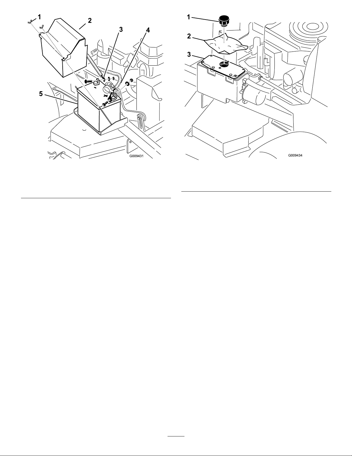
Figure1
1.Wingnut4.Positivebatterycable
2.Batterycover5.Battery
3.Negativebatterycable
3.Drainthefuelfromthefueltank.RefertoDraining
theFuelTankinMaintenance.
Figure2
1.Cap
2.Pieceofplastic
3.Hydraulictank
5.Withtwopeople,raisethefrontofthemowersoit
restsonthedrivetiresandtheplatformintheup
position.
4.Removethecapofthehydraulictankandplace
apieceofplasticovertheopeningandinstallthe
hydrauliccap.Thiswillsealthehydraulictankand
preventitfromleakingout.
6.Performanymaintenanceonthemachine.
7.Withtwopeople,lowerthefrontofthemowerto
theground.
8.Removetheplasticunderthehydraulictankcap.
9.Installthebatteryforthemachine.
3
Page 4
3
RemovingtheExistingBlades
NoPartsRequired
Procedure
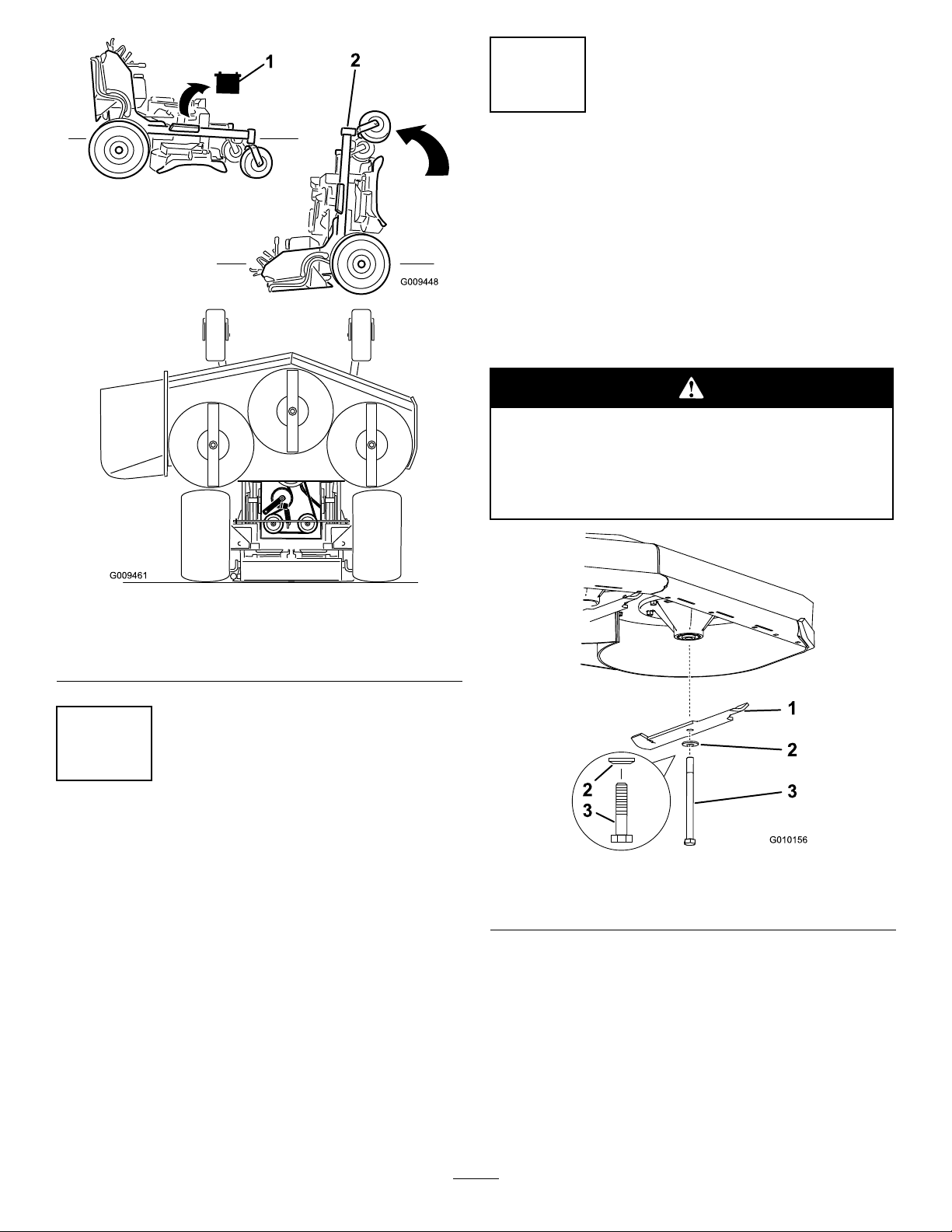
Removetheexistingbladesfromthespindles(Figure4).
Note:Savethebladesforusewheninsidedischarging
mode.Usethebladeboltandwasherforinstallingthe
recyclerbladesinStep4.
Abladeissharp.Contactwithsharpbladecan
causeseriouspersonalinjury.
Wearglovesorwrapsharpedgesoftheblade
witharag.
Figure3
1.Ensurethebatteryis
removed
2.Withtwopeople,liftthe
frontendofthemower
(ensuretheplatformisup)
2
PreparingtheMower
NoPartsRequired
Procedure
1.Thoroughlycleanmowerdeck.Alldebrismustbe
removedtoensurebafeswilltproperlyagainst
mowerdeck.
2.Repairallbentordamagedareasofmowerdeckand
replaceanymissingparts.
Figure4
1.Blade3.Bladebolt
2.Curvedwasher
4
Page 5
4
5
RemovingtheExistingBafes
NoPartsRequired
Procedure
Note:Inthestepsbelow ,theboltsarethreadedinto
themowerdeck.Removethenutsrstbeforeremoving
bolts.
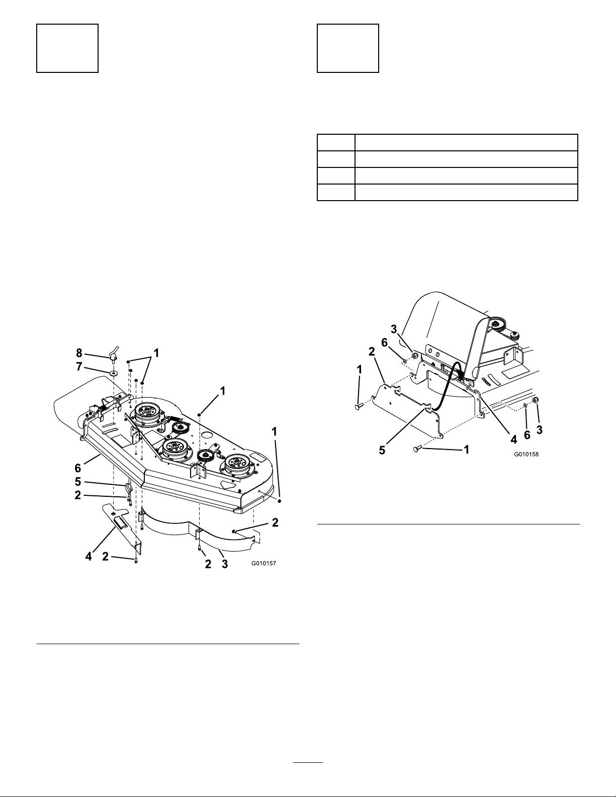
1.Removetheangenutsholdingthebafesinplace
(Figure5).
2.Removethecamlockandwasherbyunscrewingit
fromtheadjustableowbafe(Figure5).
3.Removethesixboltsholdingthebafesinplace
(Figure5).
Note:Savethebafesandhardwareforusewhen
changingtosidedischargingmode.
InstallingtheDischargePlate
Partsneededforthisprocedure:
1Dischargeplate
2
Bolt(5/16x1-1/4inches)
2
Nut(5/16inch)
2
Flatwasher(7/16inch)
Procedure
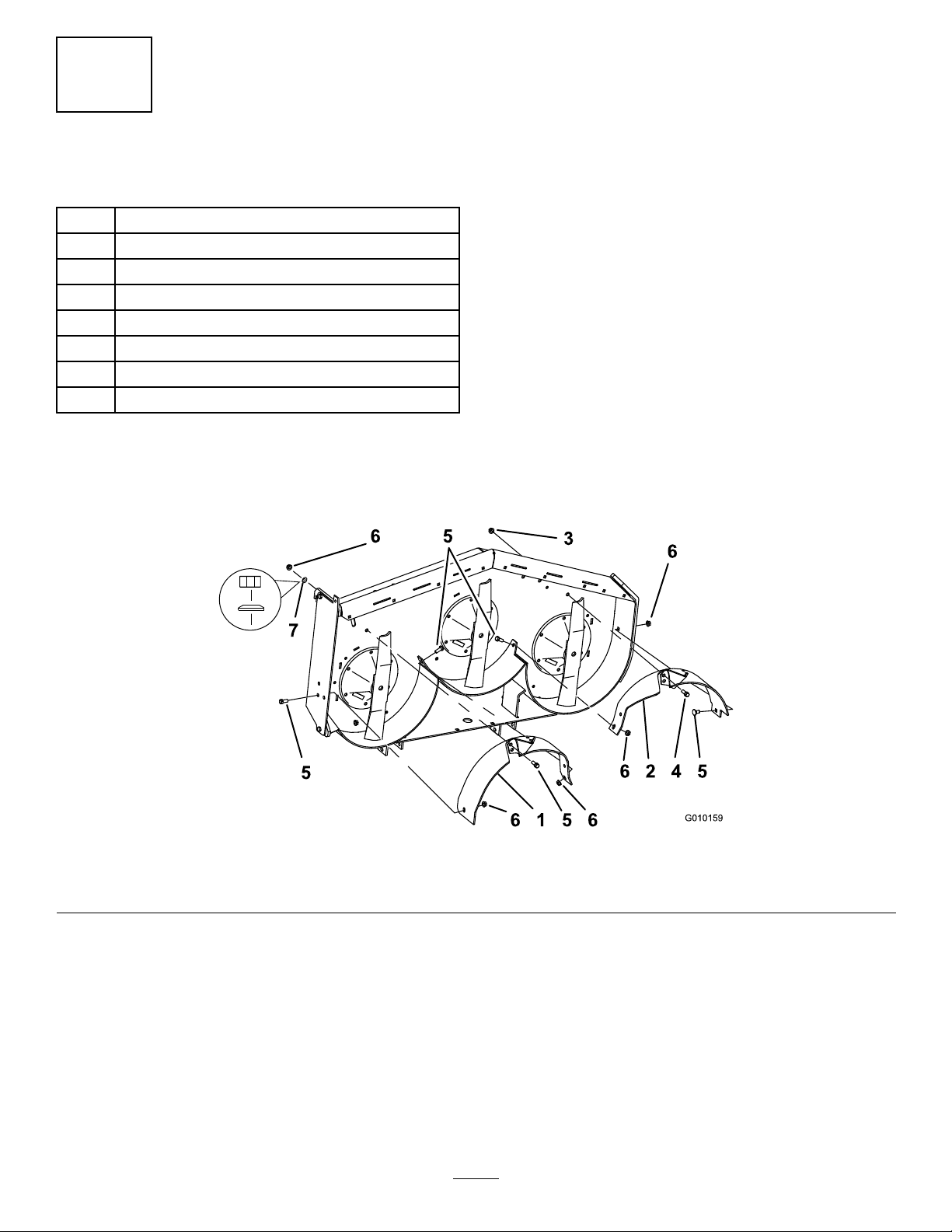
Hookthedischargeplatetotheoutsideofthemounting
bracketandsecureitwith2bolts(5/16x1-1/4inches)
and2nuts(5/16inch)(Figure6).
Figure5
1.FlangeNut
2.Bolt6.Mowerdeck
3.Leftfrontbafe
4.AdjustableFlowBafe8.Camlock
5.Dischargebafe
7.Washer
Figure6
1.Bolt(5/16x1-1/4inches)
2.Dischargeplate5.Hookondischargeplate
3.Nut(5/16inch)6.Flatwasher(7/16inch)
4.Mountingbracket
5
Page 6
Note:Looselyinstallthebafestoalignthebafes
withallexistingholesinthemower.
6
InstallingtheBafes
Partsneededforthisprocedure:
1
Leftbafe
1
Centerbafe
1
Rightbafe
7
Carriagebolt(3/8x1inch)
2
Bolt(3/8x1inch)
2
Flangenut(3/8inch)
7
Locknut(3/8inch)
1
Curvedwasher
Procedure
Note:Allholesexistinthemowerdeckforinstalling
thenewbafes.
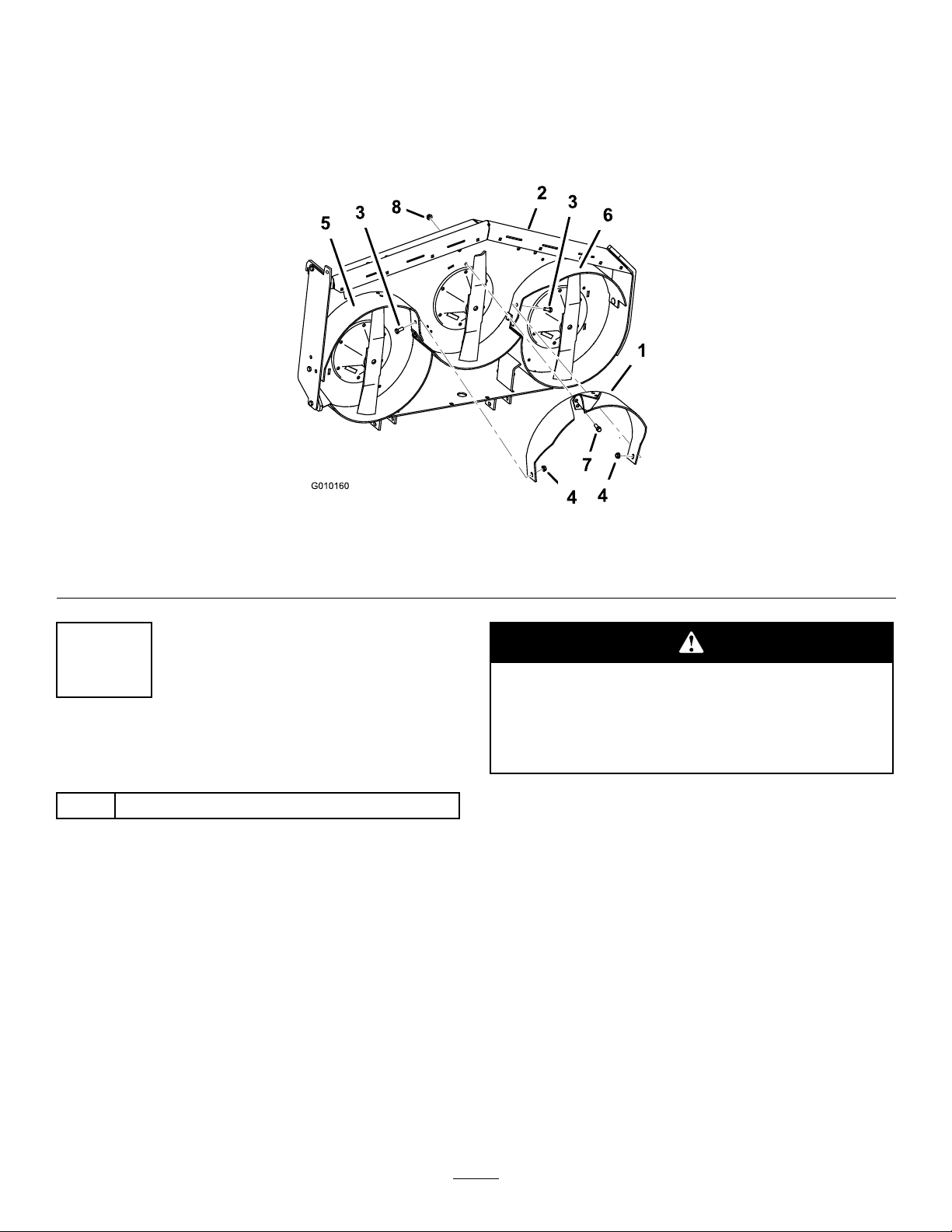
1.Installtherightbafeintothemower.
2.Looselyinstalltherightbafetothemowerdeck
with2carriagebolts(3/8x1inch),1curvedwasher
and2locknuts(3/8inch)(Figure7).
3.Looselyinstalltherightbafetothedischargeplate
with1carriagebolt(3/8x1inch)and1Locknut
(3/8inch)(Figure7).
4.Installtheleftbafeintothemower.
5.Looselyinstalltheleftbafetothemowerdeckwith
1carriagebolt(3/8x1inch)and1locknut(3/8
inch)(Figure7).
6.Looselyinstalltheleftbafetothetopofthemower
deckwith1bolt(3/8x1inch)and1angenut(3/8
inch)(Figure8).
7.Looselyinstalltheleftbafetotheleftsidewallof
themowerdeckwith1carriagebolt(3/8x1inch)
and1locknut(3/8inch)(Figure7).
Figure7
1.Rightbafe3.Flangenut(3/8inch)5.Carriagebolt(3/8x1inch)7.Curvedwasher
2.Leftbafe4.Bolt(3/8x1inch)6.Locknut(3/8inch)
6
Page 7
8.Installthecenterbafeintothemower.
9.Looselyinstallthecenterbafetotheleftbafewith
1carriagebolt(3/8x1inch)and1locknut(3/8
inch)(Figure8).
10.Looselyinstallthecenterbafetotherightbafe
with1carriagebolt(3/8x1inch)and1locknut
(3/8inch)(Figure8).
11.Looselyinstallthecenterbafetothetopofthe
mowerdeckwith1bolt(3/8x1inch)and1ange
nut(3/8inch)(Figure8).
Figure8
1.Centerbafe3.Carriagebolt(3/8x1inch)5.Rightbafe7.Bolt(3/8x1inch)
2.Mowerdeck
7
InstallingtheNewBlades
4.Flangenut(3/8inch)6.Leftbafe8.Flangenut(3/8inch)
Abladeissharp.Contactwithsharpbladecan
causeseriouspersonalinjury.
Wearglovesorwrapsharpedgesoftheblade
witharag.
Partsneededforthisprocedure:
3Recyclerblades
Procedure
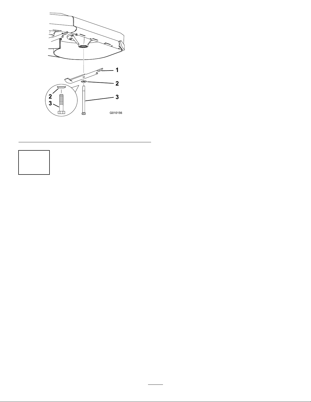
Important:Thesailpartoftheblade(i.e.,the
turnedupsection)mustfacetheinsideofthe
mower(Figure9).
1.Installthenewbladestothespindleswithwashers
andbladeboltsthatwerepreviouslyremoved
(Figure9).
2.Tightenthebladeboltto75-80ft-lb(101-108N-m).
7
Page 8
Operation
SelectingtheProper
Height-of-Cut
Removeapproximatelyoneinchornomorethan
1/3ofthegrassbladewhencutting.Inexceptionally
lushanddensegrassyoumayneedtoraisethe
height-of-cutsettingorconverttosidedischargeor
baggingoperations.
MowinginExtreme
Conditions
Figure9
1.Blade3.Bladebolt
2.Curvedwasher
8
TighteningallFasteners
NoPartsRequired
Procedure
1.Tightenallnutsandboltsforthebafes(Figure6,
Figure7andFigure8).
2.Rotatethebladesandensurethereisclearance
betweenthebladesandthebafes.Ifthereis
interference,loosenthebafeandrepositionit.
Airisrequiredtocutandrecutgrassclippingsinthe
mowerhousing,sodonotsettheheight-of-cuttoolow
ortotallysurroundthehousingbyuncutgrass.Always
trytohaveonesideofthemowerhousingfreefrom
uncutgrass,allowingairtobedrawnintothehousing.
Whenmakinganinitialcutthroughthecenterofan
uncutarea,operatethemachineslowerandbackupif
themowerstartstoclog.
MowingatProperIntervals
Undermostnormalconditionsyouwillneedtomow
every4–5days.However,grassgrowsatdifferentrates
atdifferenttimes.Thus,inordertomaintainthesame
height-of-cut,whichisagoodpractice,you’llneedto
cutmorefrequentlyinearlyspring;asthegrassgrowth
rateslowsinmidsummer,cutonlyevery8–10days.If
youareunabletomowforanextendedperioddueto
weatherconditionsorotherreasons,converttoside
dischargeorbaggingoptionsormowrstwiththe
height-of-cutatahighlevel;thenmowagain2–3days
laterwithalowerheightsetting.
MowingwithSharpBlades
Asharpbladecutscleanlyandwithouttearingor
shreddingthegrass.Adullbladewilltearandshredthe
grass.Tearingandshreddingcausesthegrasstoturn
brownattheedgeswhichimpairsgrowthandincreases
susceptibilitytodisease.
AfterOperating
Toensureoptimumperformance,cleantheunderside
ofthemowerhousingaftereachuse.Ifresidueis
allowedtobuildupinthemowerhousing,cutting
performancewilldecrease.
8
 Loading...