

Page 1
Bio-DieselFuelFilterKit
Z593/Z595SeriesRidingMowers
ModelNo.114–8228
Thiskitisformachineswithaserialnumberof
270000001andUp.
Afterthiskitisinstalled,thismachinecanusea
biodieselblendedfuelofuptoB20(20%biodiesel,80%
petrodiesel).Thepetrodieselportionshouldbelowor
ultralowsulfur.
Fuelisharmfulorfatalifswallowed.Long-term
exposuretovaporscancauseseriousinjuryand
illness.
•Avoidprolongedbreathingofvapors.
•Keepfaceawayfromnozzleandfueltankor
conditioneropening.
FormNo.3360-690RevA
InstallationInstructions
Incertainconditions,fuelisextremely
ammableandhighlyexplosive.Areor
explosionfromfuelcanburnyouandothers
andcandamageproperty.
•Wipeupanyfuelthatspills.
•Neverllthefueltankinsideanenclosed
trailer.
•Neversmokewhenhandlingfuel,andstay
awayfromanopenameorwherefuel
fumesmaybeignitedbyaspark.
•Keepfuelawayfromeyesandskin.
LooseParts
Usethechartbelowtoverifythatallpartshavebeenshipped.
ProcedureDescription
FilterandPumpAssembly1
1
2
3
4
5
Hoseclamp1
Template(locatedinthebackofthese
instructions)
SmallR-clamp
Bolt(1/4x1–1/4inches)
Locknut(1/4inch)
LargeR-clamp1
Bolt(5/16x1-3/4inches)
Bolt(5/16x3/4inch)
Locknut(5/16inch)
Waterseparator1
Hose1
Hoseclamp3
Fuelpumpharness1
Lowsulfurdecal
Fuelcap2
Dieseldecal1
Qty.
Use
Connectthefuelhosetothefuel
selector.
1
1
1
1
1
1
2
2
Drillholesforthewaterseparatorand
fuelpumpbrackets.
Installthewaterseparatorandfuel
pump.
Connectthefuelhosesandthefuel
pumpharness.
Installthedecalsandfuelcaps.
6
©2008—TheToro®Company
8111LyndaleAvenueSouth
Bloomington,MN55420
Nopartsrequired
Registeratwww.T oro.com.
–
Verifytheconnections.
OriginalInstructions(EN)
PrintedintheUSA.
AllRightsReserved
Page 2
1
ConnectingtheFuelHoseto
theFuelSelector
Partsneededforthisprocedure:
1FilterandPumpAssembly
1Hoseclamp
Procedure
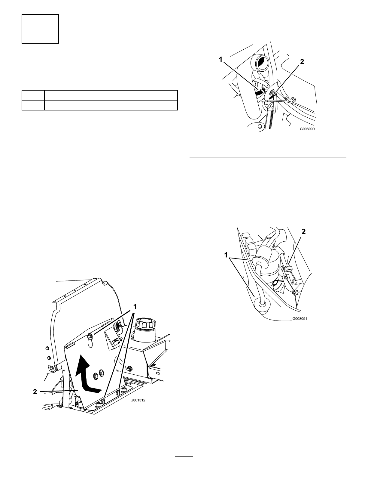
8.Removetheexistingfuellterhosefromthefuel
selectorvalve.RefertoFigure2forthecorrecthose
toremove.
Important:Allowtheenginetocoolbefore
installingthiskit.
1.Drivethemachinetoawellventilatedareaaway
fromanopenameorwherefuelfumesmaybe
ignitedbyaspark.
2.Disengagethepowertakeoff(PTO)andsetthe
parkingbrake.
3.Turnofftheengine,removethekey,andwaitforall
movingpartstostopbeforeleavingtheoperating
position.
4.Disconnectthenegativebatterycablefromthe
battery.
5.Closethefuelselectorvalve.
6.Allowtheenginetocoolbeforeinstallingthiskit.
7.Tilttheseatforwardandremovethefrontengine
panel(Figure1).
Figure2
1.Hosetoremove
9.Disconnecttheelectricalconnectionforthefuel
pumpfromthemainwireharness.Rememberthe
locationofthisconnectionbecauseitwillbeused
forthenewfuelpump.
10.Removetheexistingfuelhosefromtheengineand
removetheexistingfuelltersfromthemachine
(Figure3).
2.Closefuelselectorvalve
Figure1
1.Knob2.Frontenginepanel
Figure3
1.Existingfuellters
11.Installthenewfuellterhoseontofuelselector
valvewithahoseclamp(Figure4).
2
2.Fuelhoseconnectedto
engine
Page 3
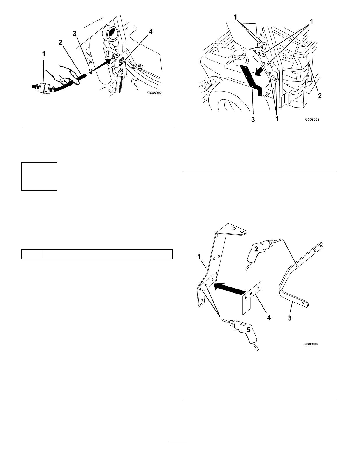
Figure4
1.Newinlinefuellter
2.Hosewithconduit
3.Hoseclamp
4.Selectorvalve
12.Routethefuellterandfuelpumptowardsthe
backoftheengine.Makesurenopartsorhosesare
touchingthemachineinareasthatwillgethot.
1.Removethesenutsand
boltsfromthehood
supportbracket
2.Removethisboltfromthe
topengineguardstrap
Figure5
3.Hoodsideplate
2
DrillingHolesfortheWater
SeparatorandFuelPump
Brackets
Partsneededforthisprocedure:
1
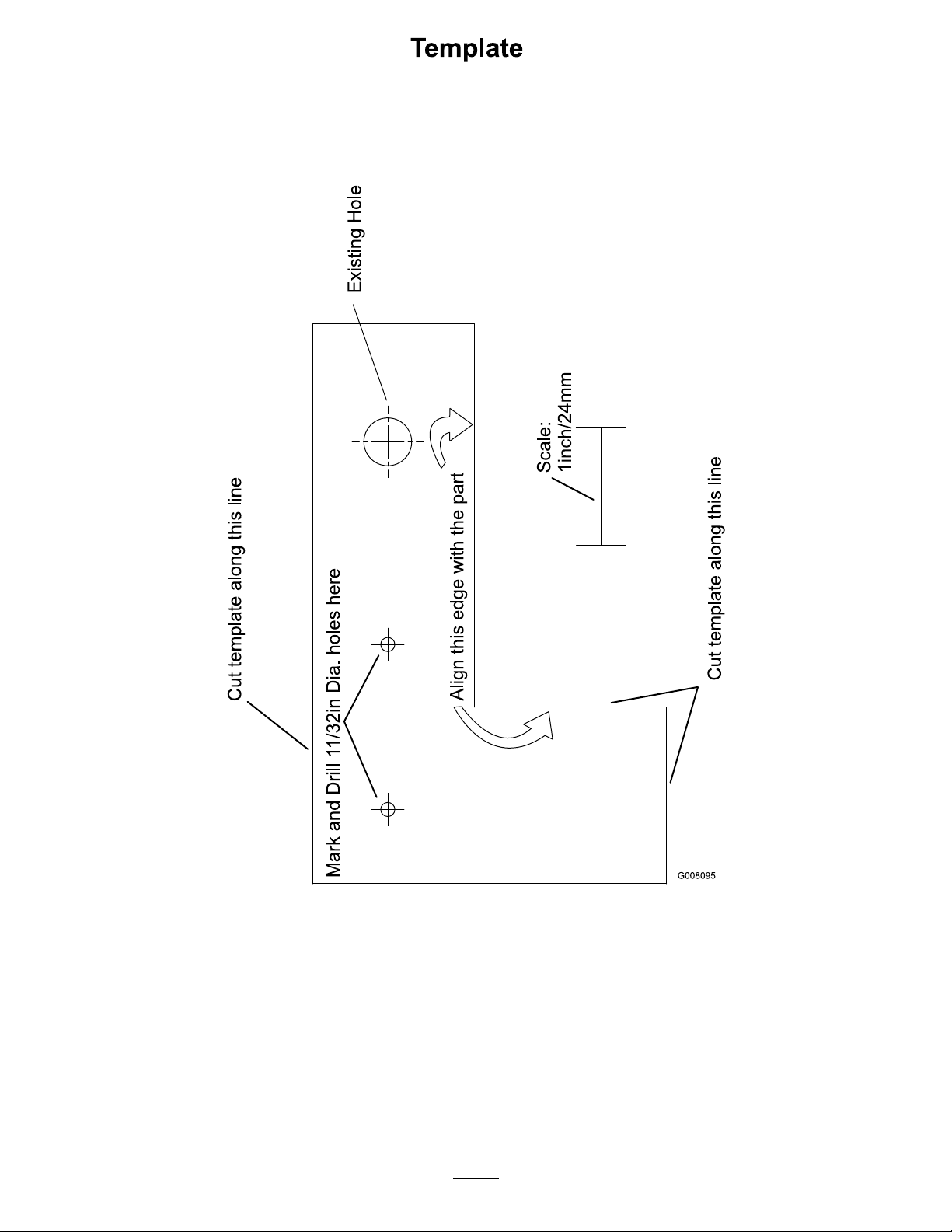
Template(locatedinthebackoftheseinstructions)
Procedure
1.Raisethehoodontheengine.
2.Removethenutsandboltsholdingthehoodsupport
bracket.Savethenutsandbolts(Figure5).
3.Removetheboltforthetopengineguardstrapfrom
themachine(Figure5).
4.Usingthepapertemplateinthebackofthese
instructions,markanddrill2holes(11/32inch
diameter)intothehoodsupportbracket(Figure6).
5.Drilla17/64inchdiameterholeintotheexisting
holeintheengineguardstrap(Figure6).
1.Hoodsideplate4.Template
2.Drilla17/64inchholeinto
theexistinghole
3.Enginestrap
3
Figure6
5.Drilltwo11/32inchholes
intothehoodsupport
brackethere
Page 4
6.Installtheengineguardstraptothebackofthe
machine.
7.Installthehoodsupportbracketwiththepreviously
removednutsandbolts.
3
InstallingtheWaterSeparator
andFuelPump
Partsneededforthisprocedure:
1
SmallR-clamp
1
Bolt(1/4x1–1/4inches)
1
Locknut(1/4inch)
1LargeR-clamp
1
Bolt(5/16x1-3/4inches)
1
Bolt(5/16x3/4inch)
2
Locknut(5/16inch)
1Waterseparator
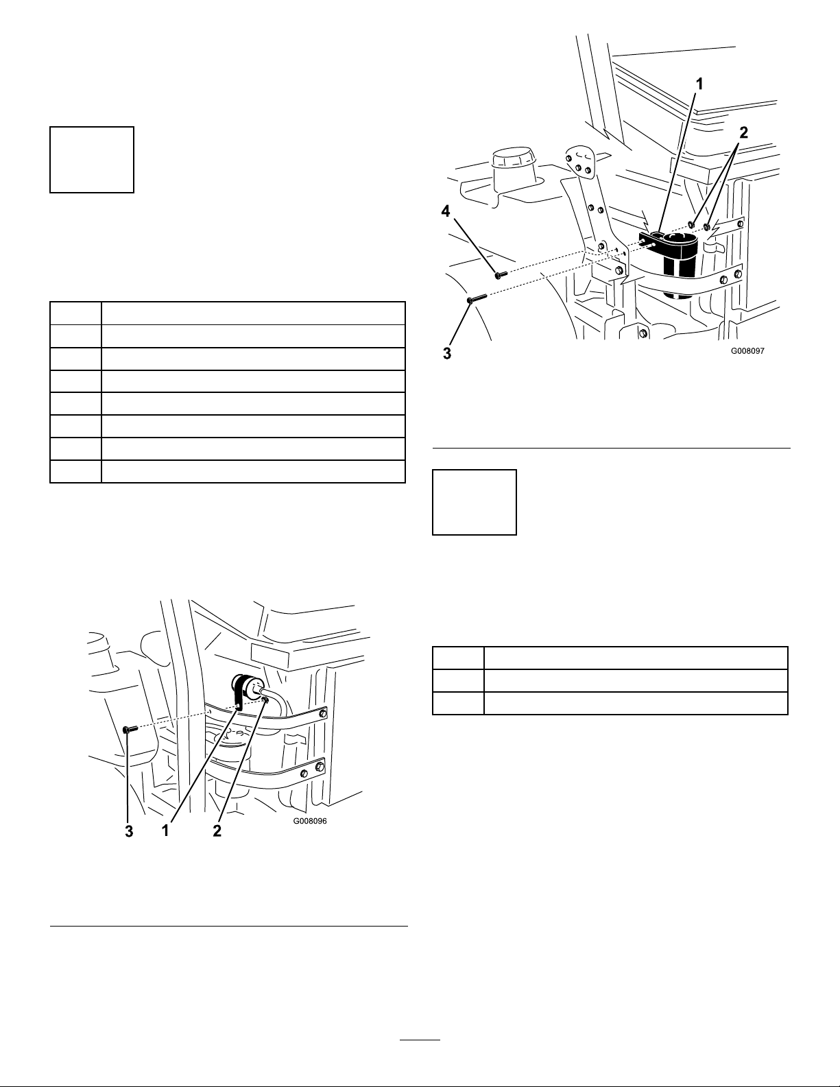
Figure8
1.LargeR-clampwithwater
separator
2.Locknut(1/4inch)4.Bolt(5/16x3/4inch)
3.Bolt(5/16x1-3/4inches)
Procedure
1.InstallthesmallR-clamparoundthefuelpumpand
installittotheenginestrapwithabolt(1/4x1–1/4
inches)andnut(1/4inch)(Figure7).
Figure7
1.SmallR-clampwithfuel
pumpinstalled
2.Bolt(1/4x1–1/4inches)
3.Locknut(1/4inch)
4
ConnectingtheFuelHoses
andtheFuelPumpHarness
Partsneededforthisprocedure:
1Hose
3Hoseclamp
1Fuelpumpharness
Procedure
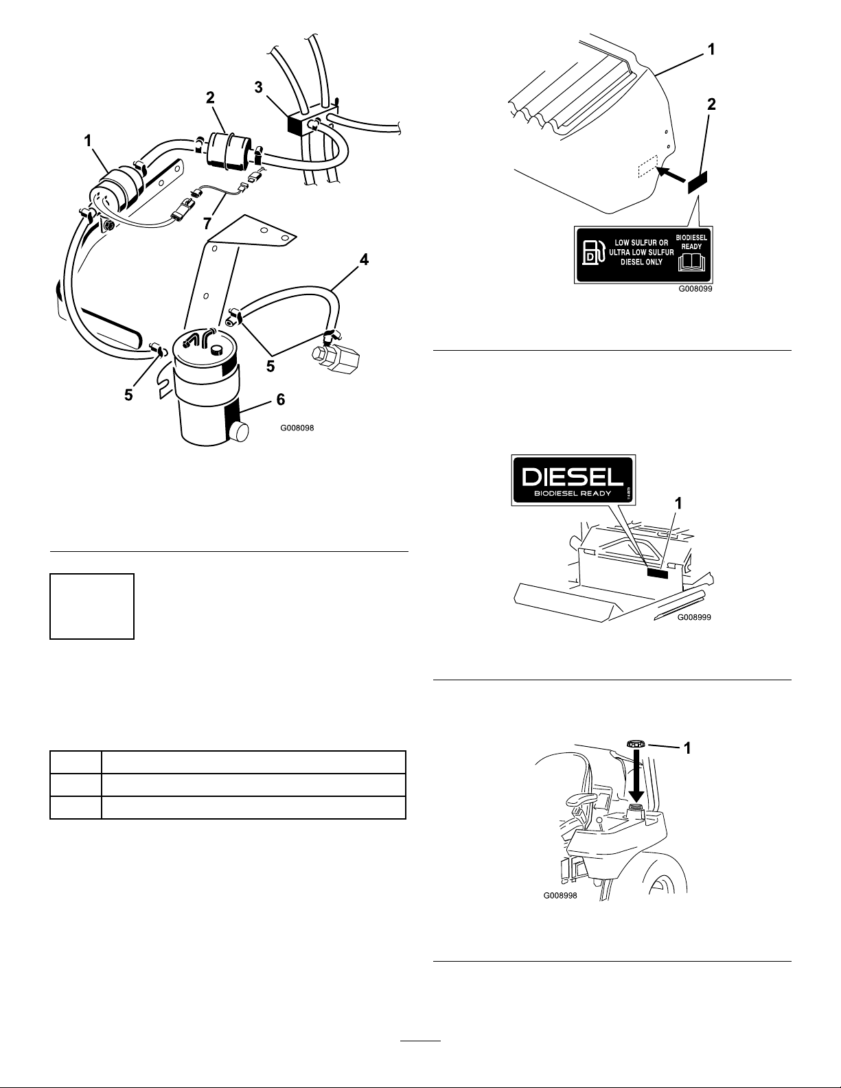
1.Installthehoseinstalledonthefuelpumptothe
waterseparatorwithahoseclamp.SeeFigure9
forthecorrectconnectiontouseonthetopofthe
waterseparator.
2.Installthehosetothewaterseparatorandtothe
enginefuelintakewith2hoseclamps(Figure9).
3.Installtheelectricalfuelpumpwiretothefuelpump
harness.
2.InstallthewaterseparatorintothelargeR-clamp
andinstallittothehoodsupportbracketwithabolt
(5/16x1-3/4inches),abolt(5/16x3/4inch),and
2locknuts(5/16inch)(Figure8).
4.Installthefuelpumpharnesstothemainwire
harness(Figure9).
4
Page 5
G008098
3
2
1
5
6
5
4
7
Figure9
G008099
1
2
G008999
1
G008998
1
1.Fuelpump5.Hoseclamp
2.Fuellter
3.Valveselector7.Fuelpumpharness
4.Hose
6.Waterseparator
Figure10
1.Enginehood
2.Lowsulfurdecal
4.Cleantheexistingfrontdecalandtheareaaroundit
andletitdry(Figure11).
5.Installthenewdieseldecalovertheexistingone.
SeeFigure11.
5
InstallingtheDecalsandFuel
Caps
Partsneededforthisprocedure:
2
2Fuelcap
1Dieseldecal
Procedure
Lowsulfurdecal
1.Lowertheenginehood.
2.Removetheexistingdecaloneachside.
3.Installalowsulfurdecaloneachsideoftheengine
hood.SeeFigure10forthecorrectposition.
Figure11
1.Dieseldecal
6.Removebothexistingfuelcapsandreplacethem
withthenewfuelcaps(Figure12).
Figure12
1.Newfuelcap
5
Page 6
Operation
6
VerifyingtheConnections
NoPartsRequired
Procedure
1.Openthefuelselectorvalve.
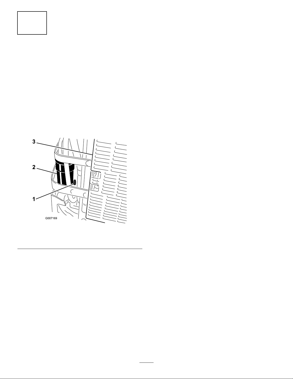
2.Openthewaterseparatordrainvalveuntilfuelstarts
todrainoutandclosethevalve(Figure13).
3.Ensuretherearenoleaksatthefuelhose
connections.
4.Installthenegativebatteryontothebattery.
5.Starttheengineandensuretherearenoleaks.
AddingFuel
Afterthiskitisinstalled,thismachinecanusea
biodieselblendedfuelofuptoB20(20%biodiesel,
80%petrodiesel).Thepetrodieselportionshouldbe
loworultralowsulfur.
Observethefollowingprecautions:
•Thebiodieselportionofthefuelmeetspecication
ASTMD6751orEN14214.
•TheblendedfuelcompositionshouldmeetASTM
D975orEN590.
•Paintedsurfacesmaybedamagedbybiodiesel
blends.
•UseB5(biodieselcontendof5%)orlesserblend
incoldweather.
•Monitorseals,hoses,gasketsincontactwithfuelas
theymaybedegradeovertime.
•Fuellterpluggingmaybeexpectedforatimeafter
convertingtobiodieselblends.
1.Drainvalve
2.Waterseparator
Figure13
3.Backofmachine
•Contactyourdistributorifyouwishformore
informationonbiodiesel.
Purchasefuelinquantitiesthatcanbeusedwithin
30daystoensurefuelfreshness.
Usesummergradedieselfuel(No.2-D)attemperatures
above20°F(-7°C)andwintergradedieselfuel(No.
1-DorNo.1-D/2-Dblend)below20°F(-7°C).Useof
wintergradedieselfuelatlowertemperaturesprovides
lowerashpointandpourpointcharacteristics,
thereforeeasingstartabilityandlesseningchances
ofchemicalseparationofthefuelduetolower
temperatures(waxappearance,whichmaypluglters).
Useofsummergradedieselfuelabove20°F(-7°C)will
contributetowardlongerlifeofthepumpcomponents.
Important:Donotusekeroseneorgasoline
insteadofdieselfuel.Failuretoobservethis
cautionwilldamagetheengine.
6
Page 7

Fuelisharmfulorfatalifswallowed.Long-term
exposuretovaporscancauseseriousinjuryand
illness.
•Avoidprolongedbreathingofvapors.
•Keepfaceawayfromnozzleandfueltankor
conditioneropening.
•Keepfuelawayfromeyesandskin.
Incertainconditions,fuelisextremely
ammableandhighlyexplosive.Areor
explosionfromfuelcanburnyouandothers
andcandamageproperty.
•Fillthefueltankoutdoors,inanopenarea,
whentheengineiscold.Wipeupanyfuel
thatspills.
•Neverllthefueltankinsideanenclosed
trailer.
•Donotllthefueltankcompletelyfull.Add
fueltothefueltankuntilthelevelis1/4to
1/2inch(6to13mm)belowthebottomof
thellerneck.Thisemptyspaceinthetank
allowsfueltoexpand.
•Neversmokewhenhandlingfuel,andstay
awayfromanopenameorwherefuel
fumesmaybeignitedbyaspark.
•Storefuelinanapprovedcontainerandkeep
itoutofthereachofchildren.Neverbuy
morethana30-daysupplyoffuel.
•Alwaysplacefuelcontainersontheground
awayfromyourvehiclebeforelling.
•Donotllfuelcontainersinsideavehicle
oronatruckortrailerbedbecauseinterior
carpetsorplastictruckbedlinersmay
insulatethecontainerandslowthelossof
anystaticcharge.
•Whenpractical,removegas-powered
equipmentfromthetruckortrailerand
refueltheequipmentwithitswheelsonthe
ground.
•Ifthisisnotpossible,thenrefuelsuch
equipmentonatruckortrailerfroma
portablecontainer,ratherthanfromafuel
dispensernozzle.
•Ifafueldispensernozzlemustbeused,keep
thenozzleincontactwiththerimofthefuel
tankorcontaineropeningatalltimesuntil
fuelingiscomplete.
FillingtheFuelTank
1.Shuttheengineoffandsettheparkingbrake.
2.Cleanaroundeachfueltankcapandremovethe
cap.Addfueltobothfueltanks,untilthelevelis
1/4to1/2inch(6to13mm)belowthebottomof
7
Page 8
thellerneck.Thisspaceinthetankallowsthefuel
toexpand.Donotllthefueltankscompletelyfull.
Maintenance
3.Installfueltankcapssecurely.Wipeupanyfuelthat
mayhavespilled.
4.Ifpossible,llthefueltankaftereachuse.Thiswill
minimizepossiblebuildupofcondensationinside
thefueltank.
ServicingtheFuelFilterand
WaterSeparator
ServiceInterval:Every40hours—Drainthewater
separator.
Every400hours/Yearly(whichever
comesrst)—Replacethefuel
lter(moreoftenindirtyordusty
conditions).
DrainingtheWaterSeparator
1.Positionthemachineonalevelsurface.
2.DisengagethePTO,movethemotioncontrollevers
totheneutrallockedpositionandsettheparking
brake.
3.Stoptheengine,removethekey ,andwaitforall
movingpartstostopbeforeleavingtheoperating
position.
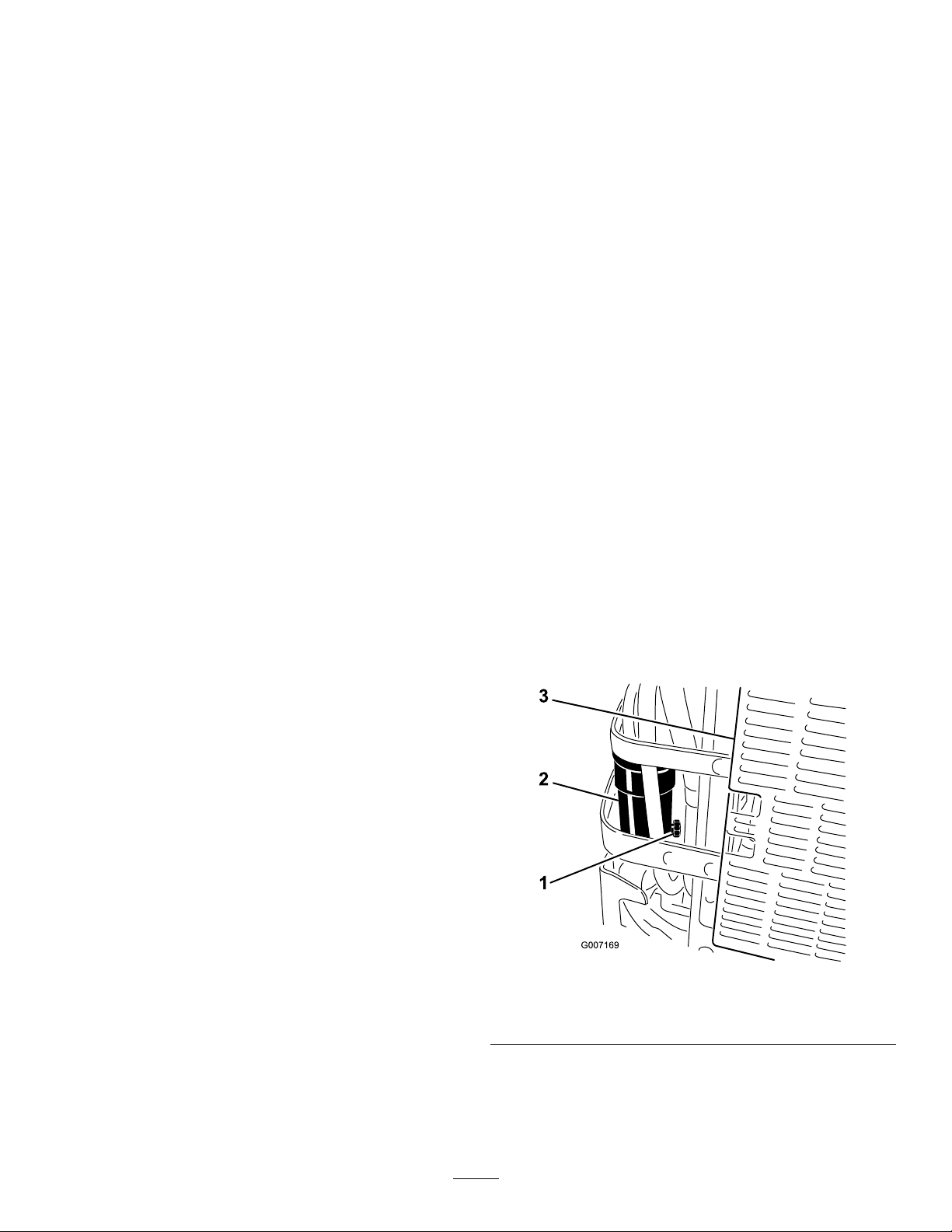
4.Locatethewaterseparatoratthebackleftofthe
machine.
5.Placeadrainpanbelowthewaterseparator.
6.Openthedrainvalveonthewaterseparator
approximatelyoneturntoallowwaterandother
contaminatestodrain(Figure14).
7.Closethedrainvalvewhenonlydieselfuelcomes
out(Figure14).
Figure14
1.Drainvalve
2.Waterseparator
3.Backofmachine
ChangingtheFuelFilter
Neverinstalladirtyfuellterifitisremovedfromthe
fuelline.
8
Page 9
1.Allowthemachinetocooldown.
2.DisengagethePTO,movethemotioncontrollevers
totheneutrallockedpositionandsettheparking
brake.
3.Stoptheengine,removethekey ,andwaitforall
movingpartstostopbeforeleavingtheoperating
position.
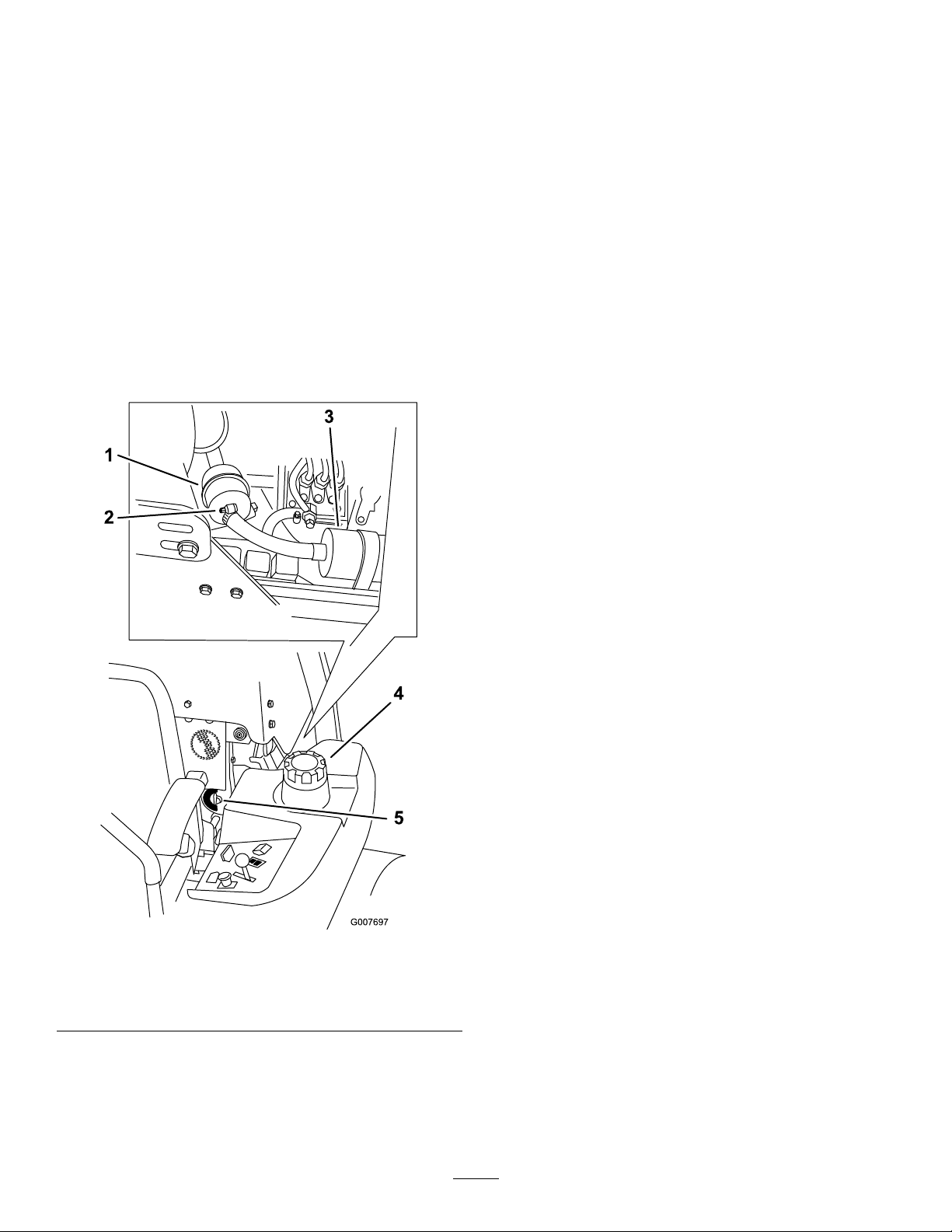
4.Closethefuelshut-offvalve(Figure15).
5.Loosenthetwohoseclampsanddisconnectthefuel
linesfromthefuellter(Figure15).
6.Installanewlter.Connectthefuellinestothefuel
lterandinstallthetwohoseclamps(Figure15).
7.Openthefuelshut-offvalve.
8.Starttheengineandcheckforleaks.
Figure15
1.Fuellter4.Leftsideofmachine
2.Hoseclamp
3.Fuelpump
5.Fuelshut-offvalve
91011
Page 10

Page 11
Page 12

 Loading...