

Page 1
ChannelReinforcementKit
Z400ZMasterMowers
ModelNo.112–8673
Note:Determinetheleftandrightsidesofthemachinefromthenormaloperatingposition.
Note:Rememberthepositionofthespacers.The
longspacersareusedfortherearboltsandtheshort
1
InstallingtheChannelPlates
spacersareusedforthefrontbolts.
12.Placethesmallchannelplateinsidetheframe
channel(Figure2).
FormNo.3360-816RevA
InstallationInstructions
Partsneededforthisprocedure:
1
Smallchannelplate
4
Bolt(1/2x3–1/2inches)
4
Flangedlocknut(1/2inch)
Procedure
1.DisengagethePTO,movethemotioncontrollevers
totheneutrallockedpositionandsettheparking
brake.
2.Stoptheengine,removethekey ,andwaitforall
movingpartstostopbeforeleavingtheoperating
position.
3.Loosenthelugnutsorboltsonthereartires
(Figure1).
4.Raisethemachinesothereartiresareofftheground
andsupportthemachinewithjackstands.
5.Removethelugnutsorboltsandreartiresfromthe
machine(Figure1).
13.Installthesmallchannelplate,wheelmotor,and
brakeassemblytotheframewiththe2shortand
longspacers,4angedlocknuts(1/2inch),and4
bolts(1/2x3-1/2inches)(Figure2).Ensurethe
spacersareinstalledinthecorrectposition.
14.Torquetheboltsbetween92to108ft-lb(125to146
N-m)
15.Connectthehydrauliclinestothewheelmotorif
removedearlier(Figure2).
16.Installthewheelhubtothewheelmotorwiththe
washerandslottednut(Figure2).
6.Removethebrakebandboltsandremovethebrake
bandfromthewheelhub(Figure1).
7.Removethecotterpinfromtheaxlenutandremove
theaxlenutandwasher(Figure1).
8.Pullthewheelhubfromthewheelmotor(Figure1).
Thismayrequiretheuseofapulleypullertoremove
it.
9.Ifneeded,removethehydrauliclinesconnectedto
thewheelmotor(Figure1).Raisetheendsabovethe
hydraulictanktopreventtheuidrunningoutand
plugthehydrauliclines.
10.Removetheretainerpinfromtheyokeatthetopof
thebrakelinkage(Figure1).
11.Removethebolts,washersandnutsholdingthe
wheelmotortotheframeandremovethewheel
motorandbrakeassembly(Figure1).
©2008—TheToro®Company
8111LyndaleAvenueSouth
Bloomington,MN55420
Registeratwww.T oro.com.
OriginalInstructions(EN)
PrintedintheUSA.
AllRightsReserved
Page 2
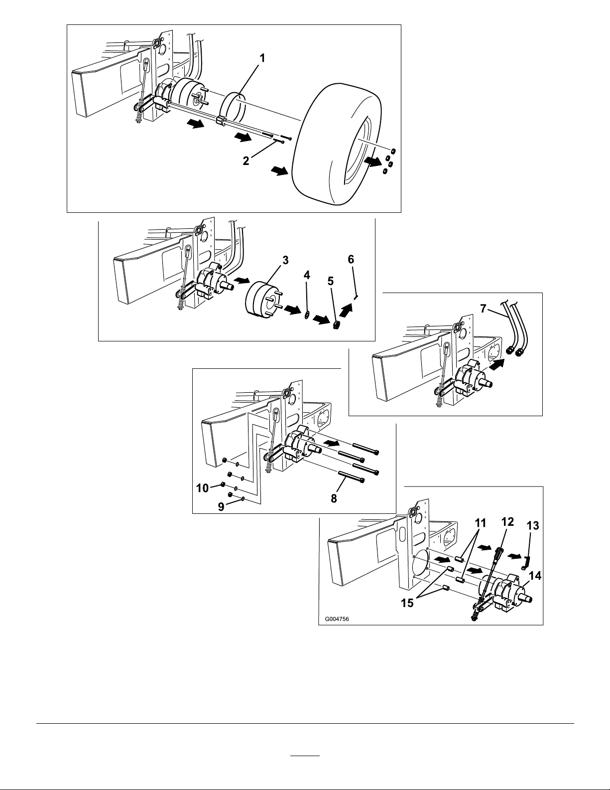
1.Brakeband
2.Brakebandbolts
3.Wheelhub
4.Washer8.Wheelmotorbolts
5.Slottednut
6.Cotterpin
7.Hydrauliclines(removeif
needed)
Figure1
9.Washers13.Retainerpin
10.Nuts14.Wheelmotor
11.Longspacer
12.Yokeatthetopofthebrake
linkage
15.Shortspacer
2
Page 3
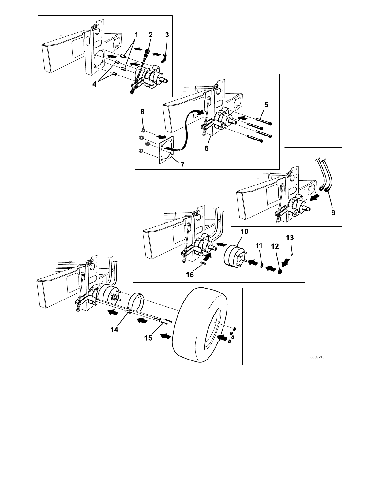
Figure2
1.Longspacer
2.Yokeatthetopofthebrake
linkage
3.Retainerpin
4.Shortspacer8.Flangedlocknut(1/2inch)12.Slottednut
5.Wheelmotorbolt(1/2x3-1/2
inches)
6.Channel
7.Smallchannelplate
9.Hydrauliclines(installif
removed)
10.Wheelhub14.Brakeband
11.Washer15.Brakebandbolts
3
13.Cotterpin
16.Key
Page 4
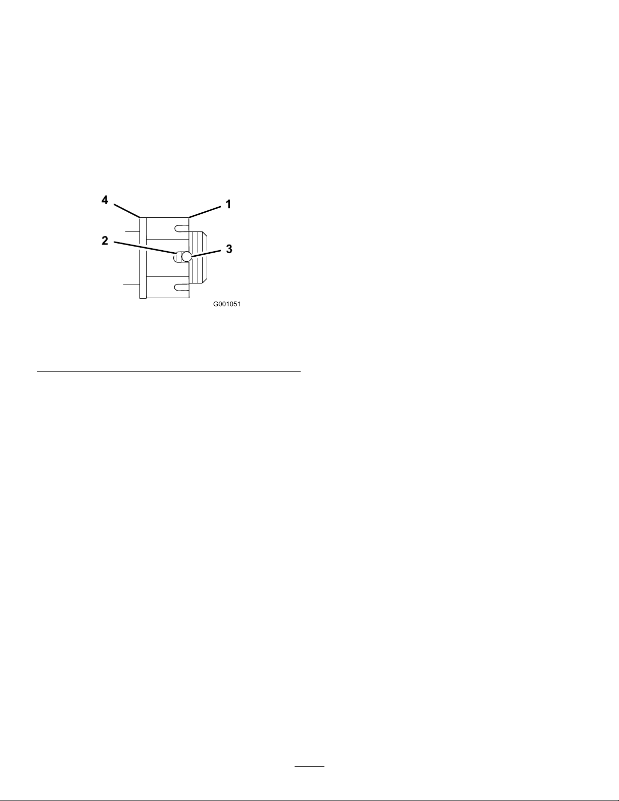
17.Torquetheslottednutto125ft-lb(170N-m)
(Figure3).
18.Checkthedistancefrombottomofslotinnutto
insideedgeofhole.Twothreadsorlessshouldbe
showing(Figure3).
19.Ifmorethantwothreadsareshowingremovenut
andinstallwasherbetweenhubandnut.
20.Tightenthenutuntilthenextsetofslotslineup
withtheholeintheshaft(Figure3).
21.Replacethecotterpin(Figure2).
Figure3
1.SlottedNut3.Holeinthreadedshaft
2.Twothreadsorless
showing
4.Washer(ifneeded)
22.Installthetirewithwheelnutsorboltstothe
machine(Figure1).
Torquethewheelnutsto95ft-lb(128N-m).
4
 Loading...