

Page 1

Form No. 3356-517 Rev A
Valve Update Kit
For Model 22910 Vibratory Plow Attachments
Model No. 112-4881
Installation Instructions
Important: If y ou intend to use a model 22910 vibrator y plo w with a TX 500 series traction
unit, y ou must fir st install this kit on the plo w . Using a 22910 vibrator y plo w on a TX 500 series
traction unit without this kit will cause major dama ge to the plo w .
Installation
Loose Parts
Use the chart below to verify that all parts have been shipped.
Step
1
2
3
No parts required
Valve plate
Bolt (5/16 x 1-1/4 inches)
Bolt (5/16 x 3-1/2 inches)
Thread locking compound (not
supplied)
Flange-head nut
Lock washer
Flow valve
Clamp plate
Hose, number 112-2766
Hose, number 105-4333
Hose, number 112-2768
Hose, number 112-2769
Elbow tting
Straight tting
T-tting
Description
Qty.
–
1
2
3
-
5
1
1
1
1
1
1
1
3
1
1
Prepare the plow.
Install the ow valve.
Connect the hoses.
Use
© 2006—The Toro® Company
8111 Lyndale Avenue South
Bloomington, MN 55420
Register at www.Toro.com. Original Instructions (EN)
Printed in the USA.
All Rights Reserved
Page 2
Step
1
Preparing the Plow
No Parts Required
Procedure
1. With the plo w attac hed to a traction unit, stop
the traction unit and stop the engine .
2. Mo v e the auxiliar y h y draulics lev er bac k and
for th a few times to reliev e h y draulic pressure
in the plo w , then disconnect the plo w h y draulic
couplers from the traction unit.
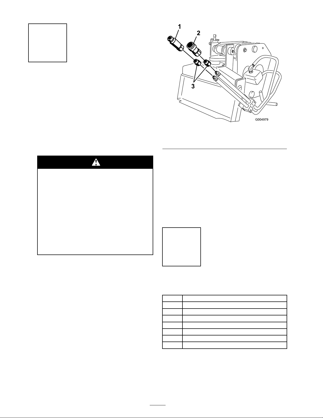
Figure 1
1. Male quick coupler
2. Female quick coupler
5. Place a drain pan under the h y draulic motor
on the plo w .
3. Adaptor (discard)
Hy draulic fluid escaping under pr essur e
can penetrate skin and cause injur y .
F luid injected into the skin must be
surgicall y r emo v ed within a few hour s by
a doctor f amiliar with this f or m of injur y
or gang r ene may r esult.
• K eep y our body and hands a w ay fr om
pin hole leaks or nozzles that eject
high pr essur e h y draulic fluid.
• Use cardboard or paper to find
h y draulic leaks; nev er use y our hands.
3. Disconnect the plo w from the traction unit.
4. R emo v e and sa v e the male and female quic k
couplers from the ends of the plo w hoses .
Discard the adaptor betw een the couplers and
the hoses ( Figure 1 ).
6. Disconnect the hoses from the elbo w fittings
on the motor .
7. R emo v e the elbo w fittings from the motor and
discard them.
8. R emo v e the fasteners securing the hose clamp
to the plo w frame , and remo v e and discard the
fasteners , clamps , and hoses .
Step
2
Installing the Flow Valve
Parts needed for this step:
1
Valve plate
2
Bolt (5/16 x 1-1/4 inches)
3
Bolt (5/16 x 3-1/2 inches)
-
Thread locking compound (not supplied)
5
Flange-head nut
1
Lock washer
1
Flow valve
1
Clamp plate
Procedure
1. Place thread loc king compound on the threads
of the 2 bolts (5/16 x 1-1/4 inc hes), and use
2 flang e-head n uts to secure the v alv e plate
2
Page 3

to the existing holes on the side of the plo w
G004981
1
3
4
2
6
5
7
frame ( Figure 2 ). T or que the fasteners to 22 to
28 ft-lb (31 to 37 N ⋅ m).
Figure 3
1. Bolt (5/16 x 3-1/2 inches)
2. Lock washer
3. Clamp plate 7. Flange-head nut
4. Flow valve
5. No. 2 port
6. No. 3 port
4. T or que the fasteners to 22 to 28 ft-lb (31 to
Figure 2
1. Plow frame 4. Flange-head nuts
2. Valve plate
3. Bolt (5/16 x 1-1/4 inches)
5. Drill 11/32 inch (9mm)
hole here.
2. Use the v alv e plate as a drilling template and
37 N ⋅ m).
Step
3
use a 11/32 inc h (9mm) drill bit to drill the 2
lo w er holes through the plo w frame ( Figure 2 ).
Connecting the Hoses
3. Install the flo w v alv e to the v alv e plate using
3 bolts (5/16 x 3-1/2 inc hes), 3 flang e-head
n uts , the clamp plate , and a loc k w asher as
illustrated in Figure 3 .
Important: T he por t on the side of
the flo w v alv e la beled “3” must f ace the
h y draulic motor and the por t mar k ed “2”
must f ace the mount plate.
Important: Add thr ead locking
compound to the thr eads of the bolts when
Parts needed for this step:
1
Hose, number 112-2766
1
Hose, number 105-4333
1
Hose, number 112-2768
1
Hose, number 112-2769
3
Elbow tting
1
Straight tting
1
T-tting
Procedure
y ou install them. If y ou do not the vibration
of the plo w will mak e the n uts f all of f.
Important: T he 4 hoses ar e similar in
appearance, y et dif fer significantl y in function.
P ay close attention to the par t n umber s
stamped on the hoses to ensur e that y ou install
them in the right place.
3
Page 4

1. Lubricate the O-rings in the ends of the fittings
with a bit of h y draulic fluid before installing .
2. Install an elbo w fitting in eac h of the por ts in
the h y draulic motor ( Figure 4 ). T he fitting
openings should face a w a y from the mount
plate when y ou are finished.
Figure 4
1. Elbow tting 3. T-tting
2. Straight tting
3. Install the straight fitting into the n umber “3”
por t on the flo w v alv e ( Figure 4 ).
4. Install the T -fitting into the n umber “2” por t
on the flo w v alv e ( Figure 4 ). T he center T
opening should face up .
5. Install the remaining elbo w fitting into the
n umber “1” por t on the bottom of the flo w
v alv e ( Figure 4 ). T he fitting opening should
face the traction unit.
6. Connect the straight end of hose n umber
112-2766 to the elbo w fitting on top of the
h y draulic motor ( Figure 5 ).
7. Connect the angled end of hose n umber
112-2766 to the center opening of the T -fitting
in por t n umber “2” of the flo w v alv e ( Figure 5 ).
8. Connect the straight end of hose n umber
105-4333 to the elbo w fitting on bottom of the
h y draulic motor ( Figure 5 ).
9. Connect the angled end of hose n umber
105-4333 to the straight fitting in por t n umber
“3” of the flo w v alv e ( Figure 5 ).
10. Connect the angled end of hose n umber
112-2768 to the elbo w fitting in por t n umber
“1” of the flo w v alv e ( Figure 5 ).
Figure 5
1. Hose, number 112-2766 3. Hose, number 112-2768
2. Hose, number 105-4333 4. Hose, number 112-2769
11. Install the male quic k coupler y ou remo v ed
from the old hose to the end of hose n umber
112-2768 ( Figure 5 ).
12. Connect the angled end of hose n umber
112-2769 to the end of the T -fitting in por t
n umber “2” of the flo w v alv e ( Figure 5 ).
13. Install the female quic k coupler y ou remo v ed
from the old hose to the end of hose n umber
112-2769 ( Figure 5 ).
14. Connect the plo w to the traction unit and
operate it, ensuring that there are no leaks .
Tighten any leaking connections .
Important: Ensur e that when y ou
operate the plo w , the blade is in the g r ound
or entering it. If y ou operate the plo w
without pr essur e fr om the g r ound on the
blade y ou may dama ge the plo w or traction
unit.
Hy draulic fluid escaping under pr essur e
can penetrate skin and cause injur y .
F luid injected into the skin must be
surgicall y r emo v ed within a few hour s by
a doctor f amiliar with this f or m of injur y
or gang r ene may r esult.
• K eep y our body and hands a w ay fr om
pin hole leaks or nozzles that eject
high pr essur e h y draulic fluid.
• Use cardboard or paper to find
h y draulic leaks; nev er use y our hands.
4
 Loading...