

Toro Greensmaster 3100, Greensmaster 3150, 112-0266 Installation Instructions Manual
Hydraulic Motor Kit
Greensmaster) 3100 and 3150
Part No. 112-0266
Form No. 3356-114 Rev A
Installation Instructions
Remove Motor and Hub
Assembly
1. Park the machine on a level surface, engage the parking
brake, lower the cutting units, and stop the engine.
Caution
If you leave the key in the ignition switch, someone
could accidently start the engine and seriously
injure you or other bystanders.
Remove the key from the ignition switch before
you do any maintenance.
2. Chock both the front wheels to prevent the machine
from moving. Lift the rear wheel off the ground using a
jack, and place blocks beneath the frame. Secure the
rear wheel off the ground.
3. Label the hydraulic motor hoses for reassembly.
Remove both hose assemblies and O–rings from the
hydraulic fittings at the hydraulic motor and hub
assembly. Plug the hoses to minimize hydraulic fluid
loss.
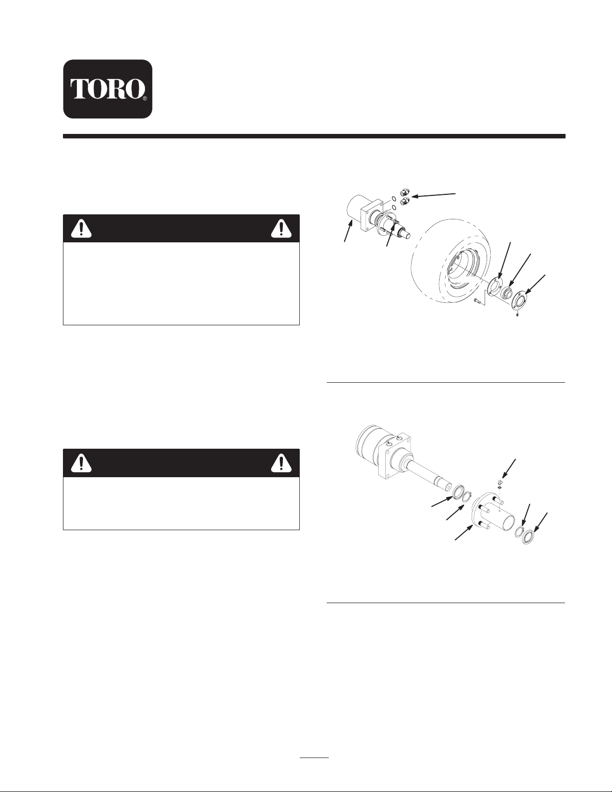
6. Remove the grease fitting from the hydraulic motor and
hub assembly (Fig. 1). Remove four lug nuts and wheel
assembly from the hub drive studs.
6
3
1
1. Motor and hub assembly
2. Grease fitting
3. Standard flangette
7. Remove the grease seal and snap ring from the long end
of the hub (Fig. 2).
2
Figure 1
4. Bearing
5. Relube flangette
6. Straight fitting (2)
4
5
Caution
Support the wheel and motor and hub assembly
during removal to prevent dropping and causing
personal injury.
4. Remove the wheel and the hydraulic motor and hub
assembly from the castor fork as follows:
A. Remove the capscrews and lock nuts securing the
flangettes and bearing tab to the castor fork (Fig. 1).
B. Remove both socket head screws, flat washers and
lock nuts securing the hydraulic motor and hub
assembly to the castor fork (Fig. 1).
C. Lower the wheel and hydraulic motor and hub
assembly from the castor fork.
5. Loosen both setscrews on bearing. Slide flangettes and
bearing off the motor shaft (Fig. 1).
4
3
2
3
1
Figure 2
1. Hub
2. Grease seal
8. Remove the snap ring and grease seal from the other
end of the shaft and remove the hub from the shaft
(Fig. 2).
9. Grease inner edge of the new grease seals with No. 2
multipurpose lithium base grease. Slide one seal onto
motor shaft past groove closest to the motor. Install
snap ring into groove(Fig. 2).
10. Slide the hub onto the shaft with the short side first.
3. Snap ring
4. Grease fitting
2
W 2006 by The Toro Company
8111 Lyndale Avenue South
Bloomington, MN 55420-1196
All Rights Reserved
Printed in the USA
1
11. Install remaining snap ring into the shaft groove. Slide
remaining new grease seal onto motor shaft.
Important The hub should spin freely in the forward
direction, but lock on the hydraulic motor shaft when it is
spun in the reverse direction.
12. Press the grease seals into the hub so they are flush with
the ends of the hub.
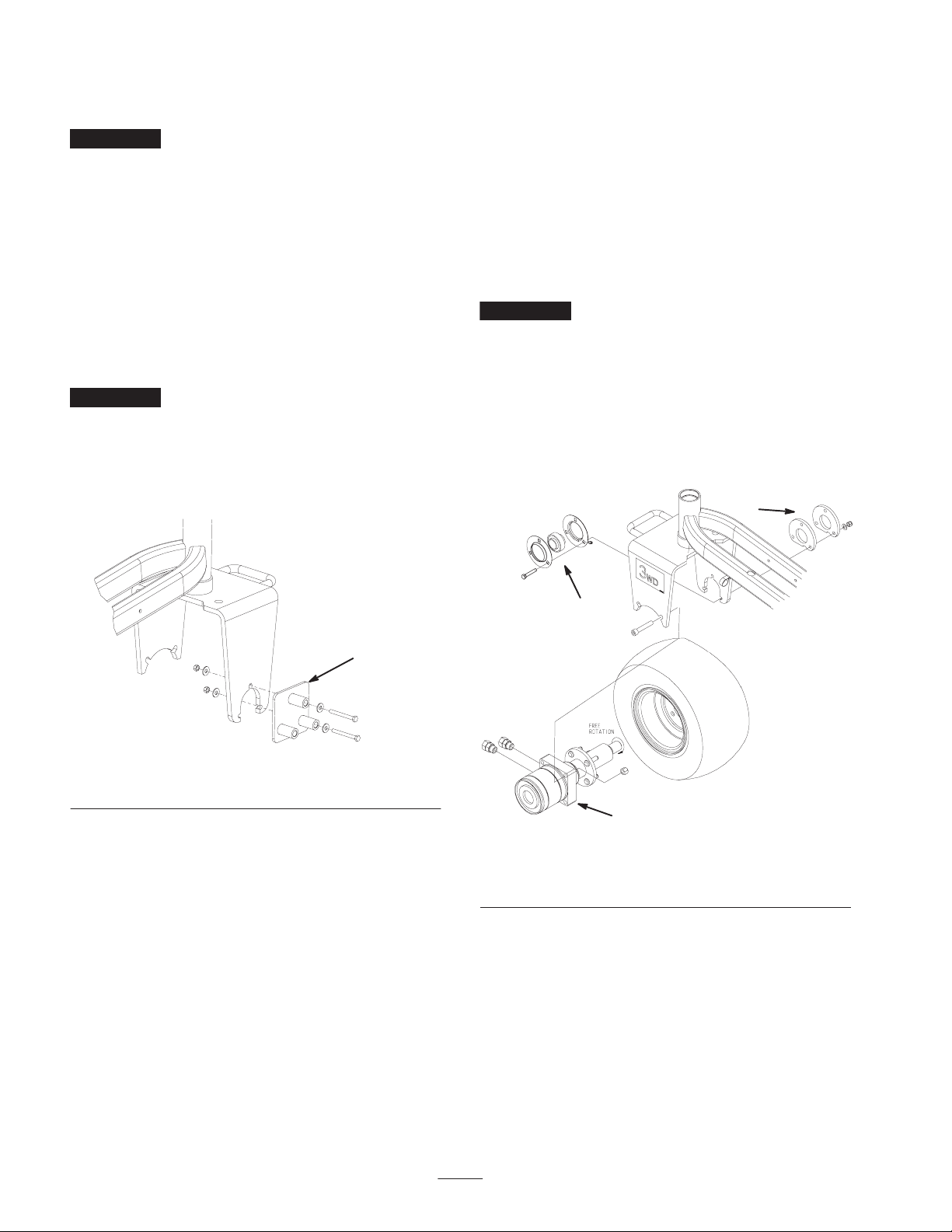
Modify Castor Fork
1. Mount the drill guide to the left side of the castor fork
with (2) 5/16 x 3 in. bolts, (4) 3/8 x 7/8 washers and
nuts. Position the components as shown in figure 3.
2. Using remaining hole in drill guide, enlarge hole in
castor fork to 9/16 in.
Important It is highly recommended that a new or
recently sharpened 9/16 in. drill bit be used. Proceed slowly
when drilling. Do not use excessive force when drilling as
jamming may occur.
3. Move the fasteners to the other holes in the drill guide
and repeat the process until all (3) holes are enlarged.
5. Position the motor hub, flangettes with bearing and tire
assembly into castor fork. Ensure that ports on motor
face rearward (Fig. 4).
6. Loosely secure motor to the inside of caster fork with
(2) socket-head screws and (2) nuts (Fig. 4).
7. Tighten motor screws to 100 ft–lbs (135 Nm).
8. Loosely assemble flangettes with bearing to inside of
castor fork with (3) new 3/8 x 2 in. screws, (2) spacer
mounts, (3) 13/32 x 13/16 hardened washers and (3)
3/8 in. locknuts.
Important Make sure no radial load is put on the motor
shaft.
Note: The grease fitting must be in the downward position
on the flangette (Fig. 4)
9. Tighten the flangette screws to 40 ft-lbs (55 N⋅m).
Note: Failure to carefully follow the above assembly
sequence may result in premature motor seal and bearing
failure.
3
1
Figure 3
1. Drill guide
Install Motor and Hub
Assembly
1. Mount the tire assembly to the motor and hub assembly
with 4 lug nuts. Torque lug nuts to 70 to 90 ft-lb (95 to
122 N⋅m).
2. Re-install the grease fitting to the hub assembly,
pointing it away from tire.
3. Insert flangettes and bearing onto end of motor shaft as
shown in Figure 4.
4. Mount the (2) straight fittings to the side of the motor
assembly (Fig. 4).
Note: Make sure all O-rings are lubricated and in position
before installing fittings.
2
1
Figure 4
1. Motor and hub assembly
2. Flangettes w/bearing
10. Apply a thread-locking adhesive (such as Loctite®) to
bearing setscrews and torque to 80 to 100 in-lb (9 to 11
N⋅m).
11. Verify overrunning bearing operation: The tire should
roll freely forward, but engage wheel motor when rolled
backward.
12. Lower rear of traction unit to ground.
13. Grease all fittings with No. 2 general purpose
lithium-based grease.
14. Re–connect the hoses to the fittings.
3. Spacer mounts (2)
2
 Loading...