

Page 1
Part No. 11 185SL (Rev. A)
Service Manual
Preface
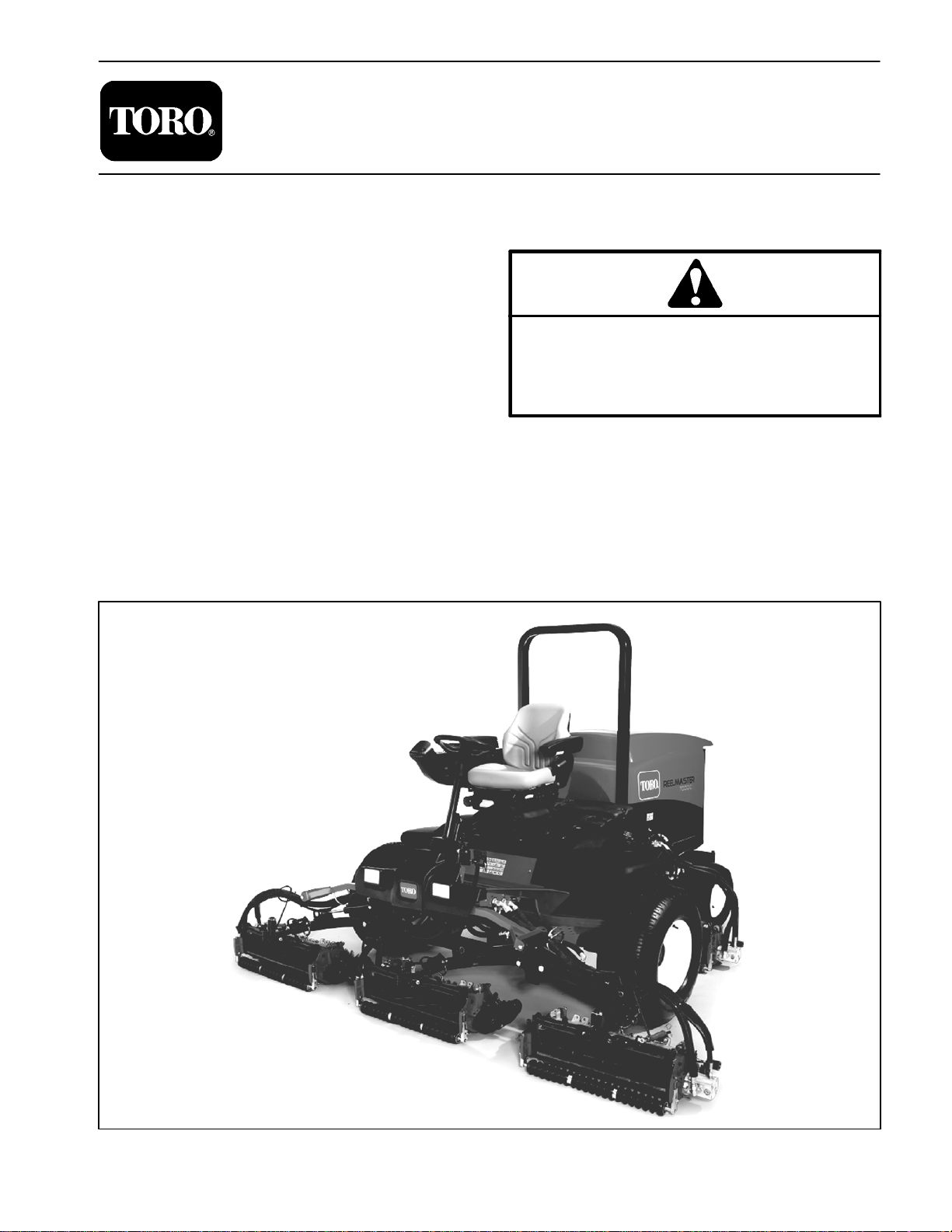
The purpose of this publication is to provide the service
technician with information for troubleshooting, testing
and repair of major systems and components on the
Reelmaster 7000.
REFER TO THE TRACTION UNIT AND CUTTING
UNIT OPERATOR’S MANUALS FOR OPERATING,
MAINTENANCE AND ADJUSTMENT INSTRUCTIONS. For reference, insert a copy of the Operator’s
ManualsandPartsCatalogfor yourmachineintoChapter 2ofthis service manual. Additional copiesof theOperator’sManuals andPartsCatalog are available onthe
internet at www.Toro.com.
TheToroCompany reserves the rightto changeproduct
specifications or this publication without notice.
Reelmaster
This safety symbol means DANGER, WARNING
or CAUTION, PERSONAL SAFETY INSTRUCTION. When you see this symbol, carefully read
the instructions that follow. Failure to obey the
instructions may result in personal injury.
NOTE: ANOTE will give general information about the
correct operation, maintenance, service, testing or repair of the machine.
IMPORTANT: The IMPORTANT notice will give importantinstructionswhichmustbefollowed to prevent damage to systems or components on the
machine.
7000
R
E The Toro Company -- 2011, 2012
Page 2

This page is intentionally blank.
Reelmaster 7000
Page 3

Table Of Contents
Chapter 1 -- Safety
General Safety Instructions 1 -- 2..................
Jacking Instructions 1 -- 4.........................
Safety and Instruction Decals 1 -- 5................
Chapter 2 -- Product Records and Maintenance
Product Records 2 -- 1...........................
Maintenance 2 -- 1...............................
Equivalents and Conversions 2 -- 2................
Torque Specifications 2 -- 3.......................
Chapter 3 -- Kubota Diesel Engine
Specifications 3 -- 2..............................
General Information 3 -- 3........................
Service and Repairs 3 -- 4........................
KUBOTA WORKSHOP MANUAL, DIESEL ENGINE,
03--M--DI--E3BSERIES
Chapter 4 -- Hydraulic System
Specifications 4 -- 3..............................
General Information 4 -- 4........................
Hydraulic Schematic 4 -- 10.......................
Hydraulic Flow Diagrams 4 -- 12...................
Special Tools 4 -- 26.............................
Troubleshooting 4 -- 30...........................
Testing 4 - - 36...................................
Adjustments 4 -- 68..............................
Service and Repairs 4 -- 69.......................
EATON MODEL 72400 SERVO CONTROLLED PIS-
TON PUMP REPAIR INFORMATION
EATONMODEL 74318 and 74348 PISTONMOTORS:
FIXED DISPLACEMENT, VALVE PLATE DESIGN
REPAIR INFORMATION
SAUER--DANFOSS STEERING UNIT TYPE OSPM
SERVICE MANUAL
Chapter 5 -- Electrical System
General Information 5 -- 2........................
Electrical Drawings 5 -- 3.........................
Special Tools 5 -- 4..............................
Troubleshooting 5 -- 6............................
Electrical System Quick Checks 5 -- 13.............
Adjustments 5 -- 15..............................
Component Testing 5 -- 17........................
Service and Repairs 5 -- 41.......................
Chapter 6 -- Axles, Planetaries and Brakes
Specifications 6 -- 2..............................
General Information 6 -- 3........................
Service and Repairs 6 -- 4........................
Chapter 7 -- Chassis
General Information 7 -- 2........................
Service and Repairs 7 -- 4........................
Chapter 8 -- DPA Cutting Units
Specifications 8 -- 2..............................
General Information 8 -- 3........................
Special Tools 8 -- 4..............................
Factors That Can Affect Cutting Performance 8 -- 8..
Set Up and Adjustments 8 -- 11....................
Service and Repairs 8 -- 14.......................
Chapter 9 -- Foldout Drawings
Hydraulic Schematic 9 -- 3........................
Electrical Schematic 9 -- 4........................
Wire Harness Drawings 9 -- 6.....................
SafetyProduct Records
and Maintenance
Kubota
Diesel Engine
System
Hydraulic
System
Electrical
Axles, Planetaries
and Brakes
Reelmaster 7000
Units
DPACutting Chassis
Foldout
Drawings
Page 4

This page is intentionally blank.
Reelmaster 7000
Page 5

Table of Contents
GENERAL SAFETY INSTRUCTIONS 2............
Before Operating 2............................
While Operating 2.............................
Maintenance and Service 3....................
JACKING INSTRUCTIONS 4.....................
SAFETY AND INSTRUCTION DECALS 5..........
Chapter 1
Safety
Safety
Reelmaster 7000 Page 1 -- 1 Safety
Page 6

General Safety Instructions
TheReelmaster 7000have beentested andcertified by
TORO for compliance with existing safety standards
and specifications. Although hazard control and accidentpreventionpartiallyaredependentupon the design
andconfiguration ofthe machine,these factorsare also
dependent upon the awareness, concern and proper
trainingofthe personnel involvedintheoperation,transport,maintenance and storage ofthe machine. Improperuseormaintenanceofthemachinecanresultininjury
ordeath.To reduce the potential for injury or death,comply with the following safety instructions.
Before Operating
WARNING
To reduce the potential for injury or death,
comply with the following safety instructions.
1. Review and understand the contents of the Operator’s Manuals and Operator’s DVD before starting and
operatingthe vehicle. Becomefamiliar with thecontrols
and know how to stop the vehicle and engine quickly.
AdditionalcopiesoftheOperator’sManualareavailable
on the internet at www.Toro.com.
2. Keep allshields, safety devices and decals in place.
Ifa shield,safetydevice ordecal isdefective, illegibleor
damaged, repair or replace it before operating the machine.Alsotighten any loosenuts,bolts orscrewsto ensure machine is in safe operating condition.
3. Assure interlock switches are adjusted correctly so
engine cannot be started unless traction pedal is in
NEUTRAL and cutting units are DISENGAGED.
While Operating
1. Sit on the seat when starting and operating the machine.
2. Before starting the engine:
A. Engage the parking brake.
4. Since diesel fuel is flammable, handle it carefully:
A. Use an approved fuel container.
B. Donotremovefueltank capwhileengineishotor
running.
C. Do not smoke w hile handling fuel.
D. Fillfuel tankoutdoorsandonly towithinan inch of
the top of the tank, not the filler neck. Do not overfill.
E. Wipe up any spilled fuel.
4. Donottouchengine,exhaustsystemcomponentsor
radiator while engine is running or soon after it is
stopped. These areas could be hot enough to cause
burns.
5. Before getting off the seat:
B. Make sure traction pedal is in neutral and the
PTO switch is OFF (disengaged).
C. Afterengine is started,releaseparkingbrakeand
keepfoot offtractionpedal. Machinemust notmove.
If movement is evident, the traction pedal linkage is
adjusted incorrectly; therefore, shut engine off and
adjust traction pedal linkage until machine does not
move when traction pedal is released.
3. Do not run engine in a c onfined area without adequate ventilation. Exhaust fumes are hazardous and
could possibly be deadly.
A. Ensure that traction pedal is in neutral.
B. Engage parking brake.
C. Disengage PTO and wait for cutting unit reel to
stop rotating.
D. Stop engine and remove key from switch.
E. Toro recommends that anytime the machine is
parked (short or long term), the cutting units should
be lowered to the ground. This relieves pressure
from the lift circuit and eliminates the risk of cutting
units accidentally lowering to the ground.
F. Do notpark on slopesunlesswheelsarechocked
or blocked.
Reelmaster 7000Page 1 -- 2Safety
Page 7

Maintenance and Service
1. TheTractionUnit andCutting Unit Operator’s Manualsprovideinformation regardingtheoperation,general
maintenance and maintenance intervals for your Reelmaster machine. Refer to these publications for additional information when servicing the machine.
2. Before servicing or making adjustments, lower cutting units, stop engine, set parking brake and remove
key from the ignition switch.
3. Make suremachine is in safe operating condition by
keeping all nuts, bolts and screws tight.
4. Never store the machine or fuel container inside
wherethereisanopenflame,suchasnearawaterheater or furnace.
5. Make sure all hydraulic line connectors are tightand
all hydraulic hoses and lines are in good condition before applying pressure to the hydraulic system.
6. Keepbodyandhandsawayfrompinholeleaksinhydrauliclines thatejecthigh pressurehydraulic fluid. Use
cardboard or paper to find hydraulic leaks. Hydraulic
fluid escaping under pressure can penetrate skin and
cause injury. Fluid accidentally injected into the skin
mustbe surgically removedwithin afew hoursby adoctor familiar with this form of injury or gangrene may result.
7. Before disconnecting or performing any work on the
hydraulic system, all pressure in system must be relieved by stopping engine and lowering cutting units to
the ground.
8. If major repairs are everneeded or assistanceis desired, contact an Authorized Toro Distributor.
9. To reduce potential fire hazard, keep engine area
free of excessive grease, grass, leaves and dirt. Clean
protective screen on machine frequently.
10.If enginemustbe runningtoperform maintenanceor
an adjustment, keep hands, feet, clothing and other
partsofthe body awayfromcutting unitsandother moving parts. Keep bystanders away.
11.Do not overspeed the engine by changing governor
setting.To assuresafetyandaccuracy,checkmaximum
engine speed.
12.Shut engine off before checking or adding oil to the
engine crankcase.
13.Disconnect battery before servicing the machine.
Disconnect negative battery cable first and positive
cablelast. If batteryvoltage isrequired fortroubleshooting or test procedures, temporarily connect the battery.
Reconnect positive battery cable first and negative
cable last.
14.Battery acid is poisonous and can cause burns.
Avoidcontact with skin, eyes and clothing. Protectyour
face, eyes and clothing when working with a battery.
15.Battery gases can explode. Keep cigarettes, sparks
and flames away from the battery.
16.When welding on machine, disconnect both battery
cables to prevent damage to machine electronic equipment. Disconnect negative battery cable first and positive cable last. Also, disconnect the wire harness
connectorfrom themachine TECcontroller anddisconnect the terminal connector from the alternator.
17.At the time of manufacture, the machine conformed
tothe safetystandards for riding mowers. Toassureoptimumperformanceand continued safetycertificationof
the machine, use genuine Toro replacement parts and
accessories.Replacementpartsandaccessoriesmade
by other manufacturers may result in non-conformance
with the safety standards and the warranty may be
voided.
18.When changing attachments, tires or performing
other service, use correct blocks, hoists and jacks.
Make sure machine is parked on a solid level surface
suchasaconcretefloor.Priortoraisingthemachine,remove any attachments that may interfere with the safe
and proper raising of the machine. Always chock or
block wheels. Use appropriate jack stands to support
the raised machine. If the machine is not properly supported by jack stands, the machine may move or fall,
whichmayresultinpersonal injury(seeJackingInstructions in this chapter).
Safety
Reelmaster 7000 Page 1 -- 3 Safety
Page 8
Jacking Instructions
CAUTION
When changing attachments, tires or performing other service, use correct jacks and supports. Make sure machine is parked on a solid,
level surface such as a concrete floor. Prior to
raising machine, remove any attachments that
may interfere with thesafe and properraising of
themachine.Alwayschockorblockwheels.Use
jackstands to support the raisedmachine. Ifthe
machine is not properly supported by jack
stands, the machine may move or fall, which
may result in personal injury.
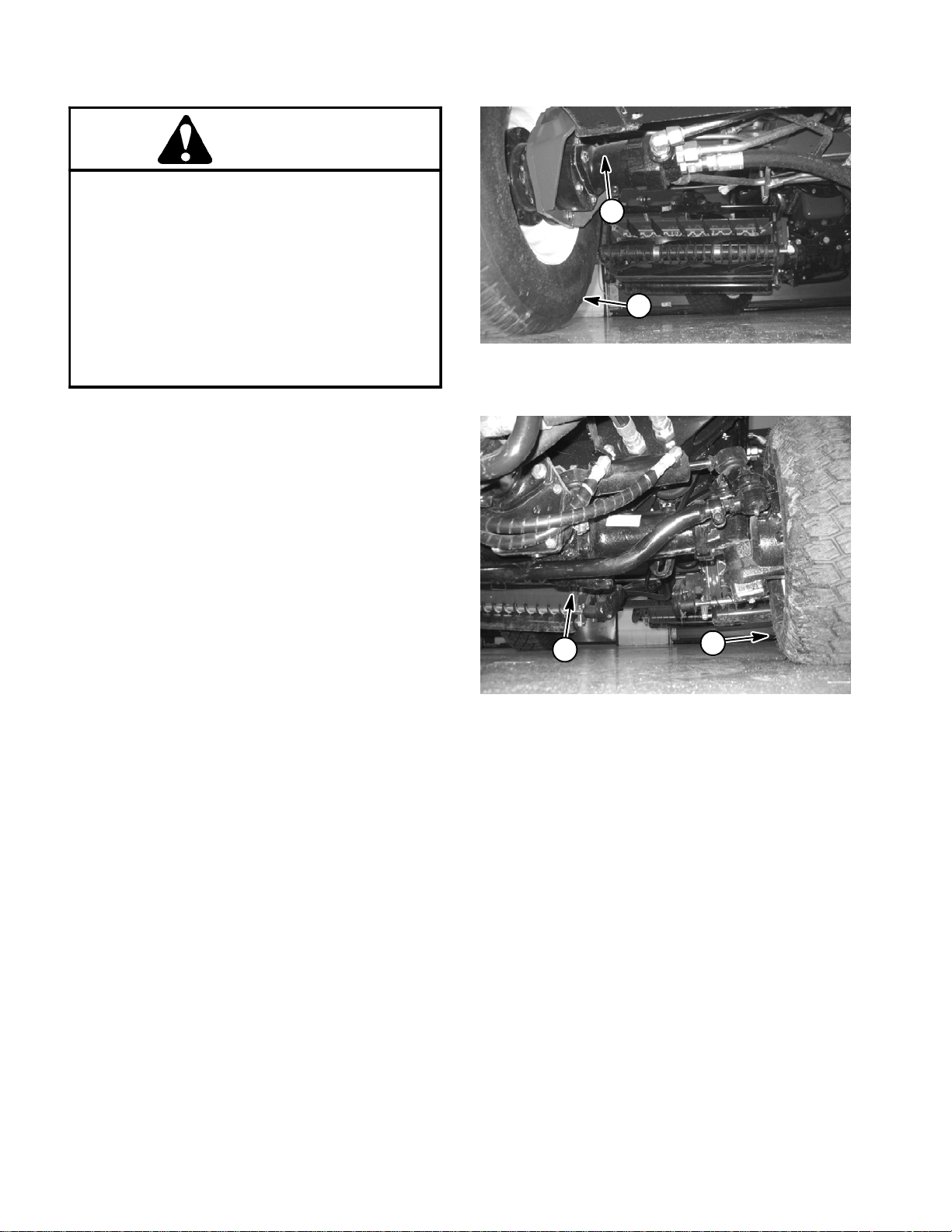
Jacking the Front End (Fig. 1)
1. Applyparking brakeand chockboth reartires toprevent the machine from moving.
IMPORTANT: Do not place jack, jack stands or
blocks under the wheel motors. Wheel motors can
be damaged if used for jacking or support points.
1
2
Figure 1
1. Frame 2. Front tire (RH shown)
2. Position jack securely underthe frame,just tothe inside of the front tire.
3. Jack front of machine off the ground.
4. Position appropriate jack stands under the frame as
close to the wheels as possible to support themachine.
Jacking the Rear End (Fig. 2)
1. Applyparkingbrakeand chock bothfronttirestoprevent the machine from moving.
2. Place jack securely under the center of rear axle.
3. Jack rear of machine off the ground.
4. Position appropriate jack stands under the rear axle
to support the machine.
1
Figure 2
1. Rear axle 2. Rear tire (RH shown)
2
Reelmaster 7000Page 1 -- 4Safety
Page 9

Safety and Instruction Decals
Numerous safety and instruction decals are affixed to
the Reelmaster 7000. If any decal becomes illegible or
damaged, install a new decal. Decal part numbers are
listed in your Parts Catalog.
Safety
Reelmaster 7000 Page 1 -- 5 Safety
Page 10

This page is intentionally blank.
Reelmaster 7000Page 1 -- 6Safety
Page 11

Product Records and Maintenance
Table of Contents
PRODUCT RECORDS 1.........................
MAINTENANCE 1...............................
EQUIVALENTS AND CONVERSIONS 2...........
Decimal and Millimeter Equivalents 2............
U.S. to Metric Conversions 2...................
TORQUE SPECIFICATIONS 3....................
Fastener Identification 3.......................
Using a Torque Wrench with an Offset Wrench 3..
Standard Torque for Dry, Zinc Plated and
Steel Fasteners (Inch Series) 4...............
Standard Torque for Dry, Zinc Plated and
Steel Fasteners (Metric Fasteners) 5...........
Other Torque Specifications 6..................
Conversion Factors 6..........................
Chapter 2
Product Records
and Maintenance
Product Records
Insert Operator’s Manuals and Parts Catalog for your
Reelmasterattheendofthischapter.Additionally,insert
Installation Instructions, Operator’s Manuals and Parts
Catalogs for any accessories that have been installed
on your Reelmaster at the end of this section.
Maintenance
Maintenanceproceduresandrecommended serviceintervals for your Reelmaster are covered in the Traction
Unit and Cutting Unit Operator’s Manuals. Refer to
those publications when performing regular equipment
maintenance. Several maintenance procedures have
break--in intervals identified in the Operator’s Manuals.
RefertotheEngineOperator’sManual foradditionalengine specific maintenance procedures.
Reelmaster 7000
Page 2 -- 1
Product Records and Maintenance
Page 12
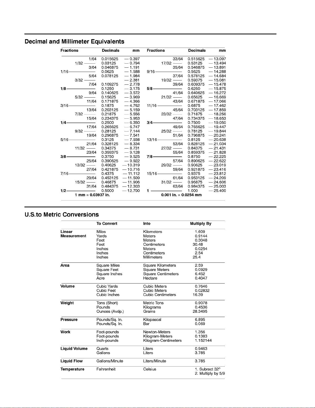
Equivalents and Conversions
0.09375
Product Records and Maintenance
Page 2 -- 2
Reelmaster 7000
Page 13
Torque Specifications
Recommended fastener torque values are listed in the
followingtables. Forcritical applications,as determined
byToro,eitherthe recommendedtorqueor atorquethat
is unique to the application is clearly identified and specified in this Service Manual.
These Torque Specifications for the installation and
tightening of fasteners shall apply toall fasteners which
donot have aspecific requirement identified in thisService Manual. The following factors shall be considered
when applying torque: cleanliness of the fastener, use
of a thread sealant (e.g. Loctite), degree of lubrication
on the fastener,presence of a prevailing torque feature
(e.g. Nylock nut), hardness of the surface underneath
thefastener’sheador similar conditionwhichaffectsthe
installation.
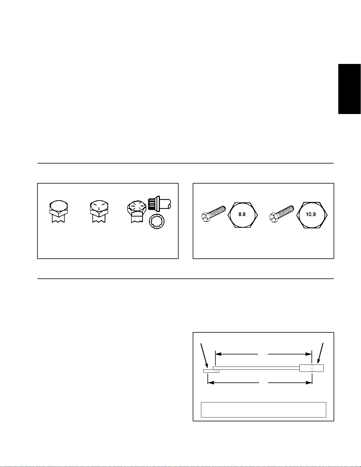
Fastener Identification
Asnotedinthefollowing tables, torquevaluesshouldbe
reduced by 25% for lubricated fasteners to achieve
the similar stress as a dry fastener. Torque values may
also have to be reduced when the fastener is threaded
into aluminum or brass. The specific torque value
should be determined based on the aluminum or brass
material strength, fastener size, length of thread engagement, etc.
The standard method of verifying torque shall be performed by marking a line on the fastener (head or nut)
and mating part, then back off fastener 1/4 of a turn.
Measurethe torque requiredto tightenthe fasteneruntil
the lines match up.
Product Records
and Maintenance
Grade 1 Grade 5 Grade 8
Inch Series Bolts and Screws
Figure 1
Using a Torque Wrench with an Offset Wrench
Useofanoffsetwrench(e.g.crowfootwrench) will affect
torquewrench calibration dueto theeffective changeof
torquewrench length.Whenusing atorque wrench with
an offset wrench, multiply the listed torque recommendation by the calculated torque conversion factor (Fig.
3) to determine proper tightening torque. Tightening
torque when using a torque wrench with an offset
wrench will be lower than the listed torque recommendation.
Example: The measured effective length of the torque
wrench (distance from the center of the handle to the
center of the square drive) is 18”.
Themeasuredeffectivelengthofthetorquewrenchwith
the offset wrench installed (distance from the center of
the handle to the center of the offset wrench) is 19”.
Class 8.8 Class 10.9
Metric Bolts and Screws
Figure 2
If the listed torque recommendation for a fastener is
from 76 to 94 ft--lb, the proper torque when using this
torque wrench with an offset wrench would be from 72
to 89 ft--lb.
(effective length of
torque wrench)
A
B
(effective length of torque
wrench + offset wrench)
TORQUE CONVERSION FACTOR = A / B
Torque wrenchOffset wrench
The calculated torque conversion factor for this torque
wrenchwith thisoffsetwrench would be18 /19 =0.947.
Reelmaster 7000
Page 2 -- 3
Figure 3
Product Records and Maintenance
Page 14
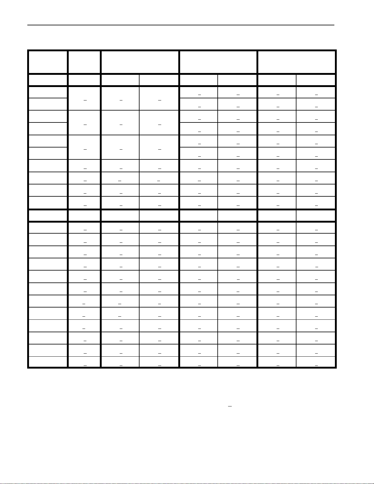
Standard Torque for Dry, Zinc Plated and Steel Fasteners (Inch Series)
Thread Size
# 6 -- 32 UNC
# 6 -- 40 UNF
# 8 -- 32 UNC
# 8 -- 36 UNF
#10--24UNC
#10--32UNF
1/4 -- 20 UNC 48 + 7 53 + 7 599 + 79 100 + 10 1130+ 113 140 + 15 1582+ 169
1/4 -- 28 UNF 53 + 7 65 + 10 734 + 113 115 + 12 1299 + 136 160 + 17 1808+ 192
5/16 -- 18 UNC 115 + 15 105 + 15 1186 + 169 200 + 25 2260 + 282 300 + 30 3390 + 339
5/16 -- 24 UNF 138 + 17 128 + 17 1446 + 192 225 + 25 2542 + 282 325 + 33 3672 + 373
3/8 -- 16 UNC 16 + 2 16 + 2 22+ 3 30 + 3 41 + 4 43 + 5 58 + 7
Grade 1, 5 &
8withThin
Height Nuts
in--lb in--lb N--cm in--lb N--cm in--lb N--cm
10 + 2 13 + 2 147 + 23
13 + 2 25 + 5 282 + 30
18 + 2 30 + 5 339 + 56
ft--lb ft--lb N--m ft--lb N--m ft--lb N--m
SAE Grade 1 Bolts, Screws, Studs &
Sems with Regular Height Nuts
(SAE J995 Grade 2 or Stronger Nuts)
SAE Grade 5 Bolts, Screws, Studs &
Sems with Regular Height Nuts
(SAE J995 Grade 2 or Stronger Nuts)
15 + 2 169 + 23 23 + 3 262 + 34
17 + 2 192 + 23 25 + 3 282 + 34
29 + 3 328 + 34 41 + 5 463 + 56
31 + 4 350 + 45 43 + 5 486 + 56
42 + 5 475 + 56 60 + 6 678 + 68
48 + 5 542 + 56 68 + 7 768 + 79
SAE Grade 8 Bolts, Screws, Studs &
Sems with Regular Height Nuts
(SAE J995 Grade 5 or Stronger Nuts)
3/8 -- 24 UNF 17 + 2 18 + 2 24 + 3 35 + 4 47 + 5 50 + 6 68 + 8
7/16 -- 14 UNC 27 + 3 27 + 3 37 + 4 50 + 5 68 + 7 70 + 7 95 + 9
7/16 -- 20 UNF 29 + 3 29 + 3 39 + 4 55 + 6 75 + 8 77 + 8 104 + 11
1/2 -- 13 UNC 30 + 3 48 + 7 65 + 9 75 + 8 102 + 11 105 + 11 142 + 15
1/2 -- 20 UNF 32 + 4 53 + 7 72 + 9 85 + 9 115 + 12 120 + 12 163 + 16
5/8 -- 11 UNC 65 + 10 88 + 12 119 + 16 150 + 15 203 + 20 210 + 21 285+ 28
5/8 -- 18 UNF 75 + 10 95+ 15 129 + 20 170 + 18 230 + 24 240 + 24 325+ 33
3/4 -- 10 UNC 93 + 12 140 + 20 190 + 27 265 + 27 359 + 37 375 + 38 508 + 52
3/4 -- 16 UNF 115 + 15 165 + 25 224 + 34 300 + 30 407 + 41 420 + 43 569 + 58
7/8 -- 9 UNC 140 + 20 225 + 25 305 + 34 430 + 45 583+ 61 600 + 60 813 + 81
7/8 -- 14 UNF 155 + 25 260 + 30 353 + 41 475 + 48 644 + 65 667 + 66 904 + 89
NOTE: Reduce torque values listed in the table above
by 25% for lubricated fasteners. Lubricated fasteners
are defined as threads coated with a lubricant such as
engine oil or thread sealant such as Loctite.
NOTE: The nominal torque values listed above for
Grade 5 and 8 fasteners are based on 75% of the minimumproof load specifiedin SAE J429. The toleranceis
approximately +
10% of the nominal torque value. Thin
height nuts include jam nuts.
NOTE: Torque values may have to be reduced when
installing fasteners into threaded aluminum or brass.
The specific torque value should be determined based
on the fastener size, the aluminum or base material
strength, length of thread engagement, etc.
Product Records and Maintenance
Page 2 -- 4
Reelmaster 7000
Page 15
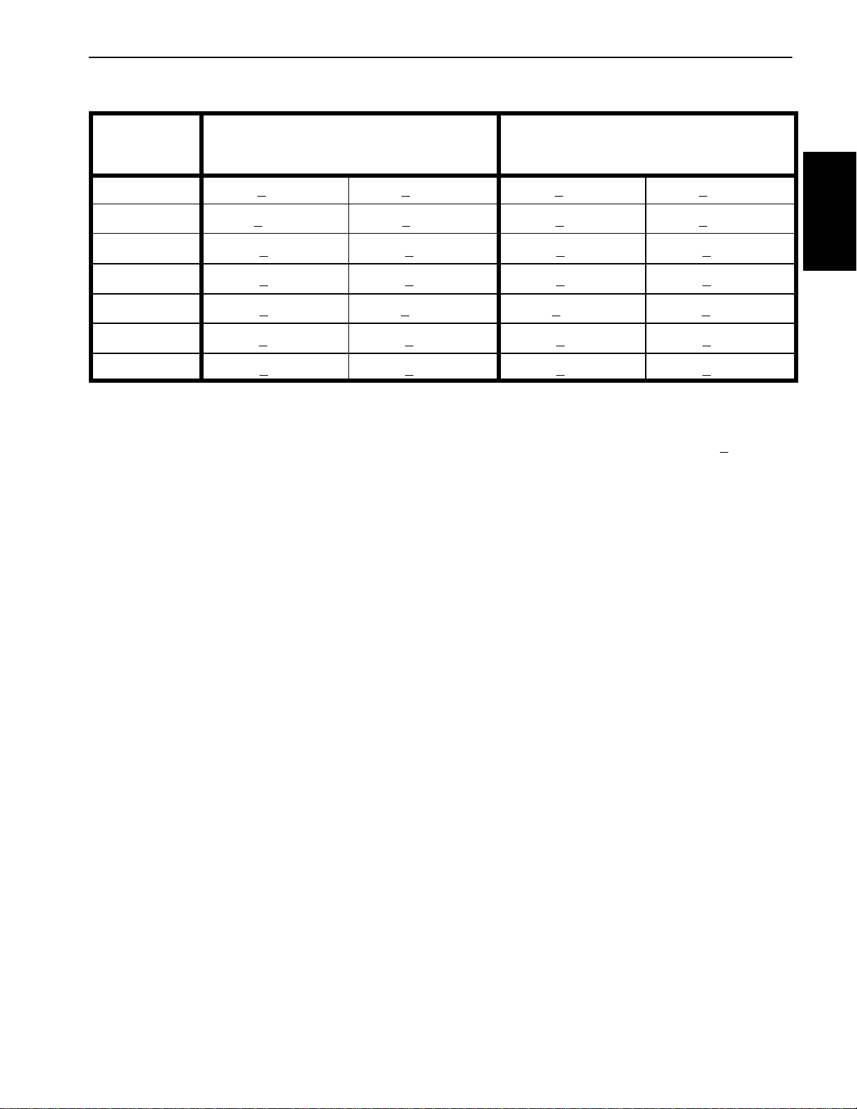
Standard Torque for Dry, Zinc Plated and Steel Fasteners (Metric Series)
Class 8.8 Bolts, Screws and Studs with
Thread Size Regular Height Nuts
(Class 8 or Stronger Nuts)
Class 10.9 Bolts, Screws and Studs with
Regular Height Nuts
(Class 10 or Stronger Nuts)
M5 X 0.8 57 + 6in--lb 644 + 68 N--cm 78 + 8in--lb 881 + 90 N--cm
M6 X 1.0 96 + 10 in--lb 1085 + 113 N- -cm 133 + 14 in--lb 1503 + 158 N--cm
M8 X 1.25 19 + 2ft--lb 26 + 3N--m 28 + 3ft--lb 38 + 4N--m
M10 X 1.5 38 + 4ft--lb 52 + 5N--m 54 + 6ft--lb 73 + 8N--m
M12 X 1.75 66 + 7ft--lb 90 + 10 N--m 93+ 10 ft--lb 126 + 14 N--m
M16 X 2.0 166+ 17 ft--lb 225 + 23 N--m 229 + 23 ft--lb 310 + 31 N--m
M20 X 2.5 325 + 33 ft--lb 440 + 45 N--m 450 + 46 ft--lb 610 + 62 N--m
NOTE: Reduce torque values listed in the table above
by 25% for lubricated fasteners. Lubricated fasteners
are defined as threads coated with a lubricant such as
engine oil or thread sealant such as Loctite.
NOTE: The nominal torque values listed above are
based on 75% of the minimum proof load specified in
SAEJ1199.Thetoleranceisapproximately+
nominal torque value.
NOTE: Torque values may have to be reduced when
installing fasteners into threaded aluminum or brass.
The specific torque value should be determined based
on the fastener size, the aluminum or base material
strength, length of thread engagement, etc.
10%ofthe
Product Records
and Maintenance
Reelmaster 7000
Page 2 -- 5
Product Records and Maintenance
Page 16
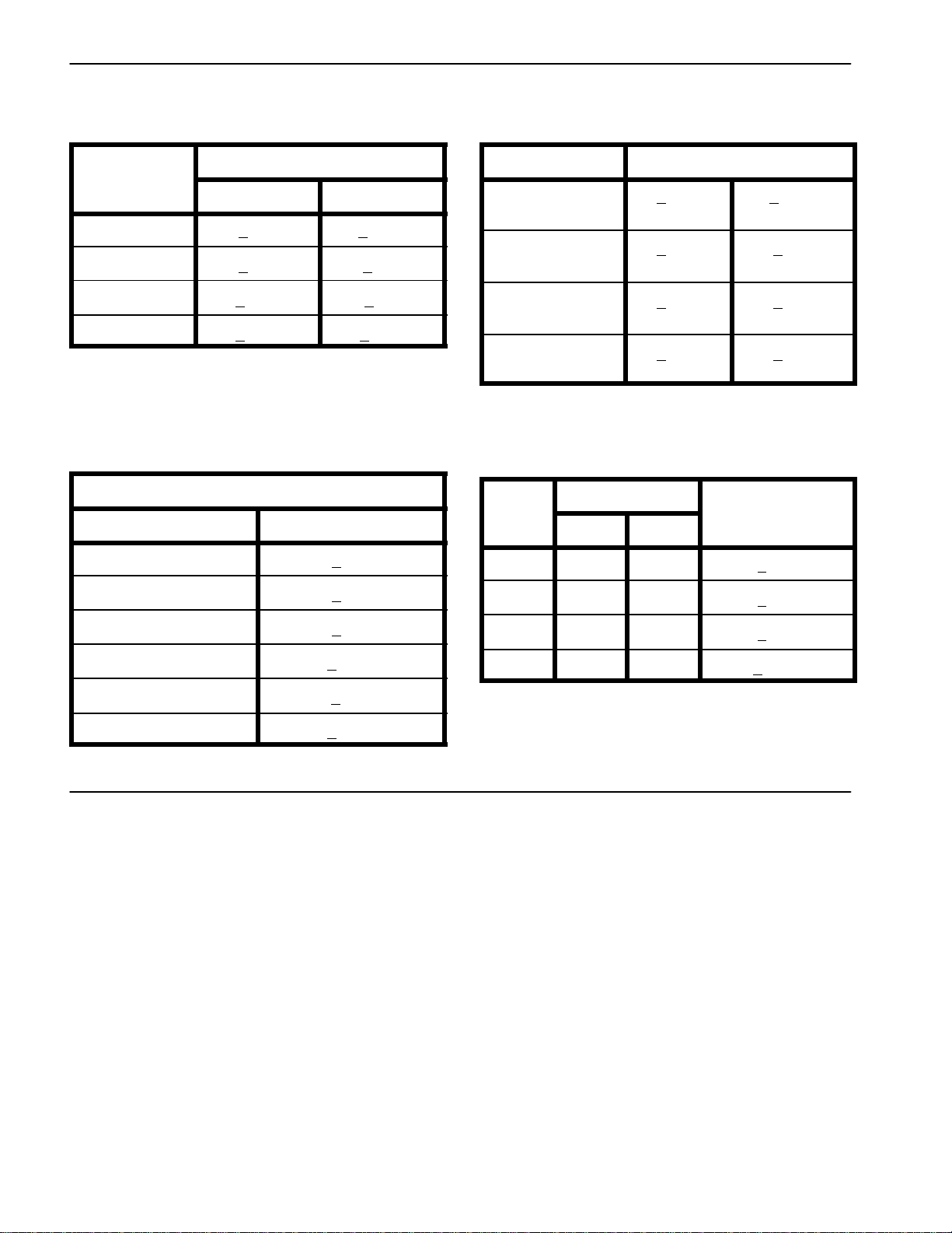
Other Torque Specifications
*
SAE Grade 8 Steel Set Screws
Recommended Torque
Thread Size
Square Head Hex Socket
1/4 -- 20 UNC 140 + 20 in--lb 73+ 12 in--lb
5/16 -- 18 UNC 215 + 35 in--lb 145 + 20 in--lb
3/8 -- 16 UNC 35 + 10 ft--lb 18 + 3ft--lb
1/2 -- 13 UNC 75 + 15 ft--lb 50 + 10 ft--lb
Thread Cutting Screws
(Zinc Plated Steel)
Type 1, Type 23 or Type F
Thread Size Baseline Torque*
No. 6 -- 32 UNC 20 + 5in--lb
Wheel Bolts and Lug Nuts
Thread Size
7/16 -- 20 UNF
Grade 5
1/2 -- 20 UNF
Grade 5
M12 X 1.25
Class 8.8
M12 X 1.5
Class 8.8
** For steel wheels and non--lubricated fasteners.
Thread Cutting Screws
(Zinc Plated Steel)
Thread
Size
No. 6 18 20 20 + 5in--lb
Threads per Inch
Type A Type B
Recommended Torque**
65 + 10 ft--lb 88 + 14 N--m
80 + 10 ft--lb 108+ 14 N--m
80 + 10 ft--lb 108+ 14 N--m
80 + 10 ft--lb 108+ 14 N--m
Baseline Torque
No. 8 -- 32 UNC 30 + 5in--lb
No. 10 -- 24 UNC 38 + 7in--lb
1/4 -- 20 UNC 85 + 15 in--lb
5/16 -- 18 UNC 110 + 20 in--lb
3/8 -- 16 UNC 200 + 100 in--lb
Conversion Factors
in--lb X 11.2985 = N--cm N--cm X 0.08851 = in--lb
ft--lb X 1.3558 = N--m N--m X 0.7376 = ft--lb
No. 8 15 18 30 + 5in--lb
No. 10 12 16 38 + 7in--lb
No. 12 11 14 85 + 15 in--lb
*Holesize,materialstrength,materialthickness andfinish must be considered when determining specific
torquevalues.Alltorquevalues arebasedonnon--lubricated fasteners.
Product Records and Maintenance
Page 2 -- 6
Reelmaster 7000
Page 17

Table of Contents
SPECIFICATIONS 2.............................
GENERAL INFORMATION 3.....................
Operator’s Manual 3..........................
SERVICE AND REPAIRS 4......................
Air Filter System 4............................
Exhaust System 6............................
Fuel System 8................................
Check Fuel Lines and Connections 9...........
Drain and Clean Fuel Tank 9..................
Fuel Tank Removal 9........................
Fuel Tank Installation 9.......................
Radiator 10..................................
Engine 12....................................
Engine Removal 13..........................
Engine Installation 14........................
Pump Adapter Plate 16........................
KUBOTA WORKSHOP MANUAL, DIESEL ENGINE,
03--M--DI--E3B SERIES
Chapter 3
Kubota Diesel Engine
Kubota
Diesel Engine
Reelmaster 7000 Page 3 -- 1 Kubota Diesel Engine
Page 18

Specifications
Item Description
Make / Designation Kubota Model V2403--M--DI--E3B
Bore 3.425” (87.0 mm)
Stroke 4.031” (102.4 mm)
Total Displacement 148.5 in3(2434 cc)
Firing Order 1 (closest to gear case end) -- 3 -- 4 (closest to flywheel end) -- 2
Combustion Chamber Spherical Type (E--TVCS)
Compression Ratio 23.2:1
Direction of Rotation Counterclockwise (viewed from flywheel)
Fuel Diesel or Biodiesel (up to B20) Fuel with Low or Ultra Low
Fuel Capacity 22 U.S. gallons (83 liters)
Fuel Injection Pump Denso PFR 4M Type Mini Pump
Injection Nozzle Denso OPD Mini Nozzle
4--Cycle, 4 Cylinder, Liquid Cooled, Diesel Engine
Sulfur Content
Governor Centrifugal Mechanical
Low Idle (no load) 1550 + 50 RPM
High Idle (no load) 2850 +50/--120 RPM
Engine Oil API CH--4, CI--4 or higher
Engine Oil Viscosity See Operator’s Manual
Crankcase Oil Capacity 10.0 U.S. Quarts (9.5 Liters) with Filter
Oil Pump Trochoid Type
Coolant Capacity 13 U.S. Quarts (12.3 Liters)
Starter 12 VDC, 2.0 kW
Alternator/Regulator 12 VDC
Alternator Output 60 amp
Engine Dry Weight 406 U.S. pounds (184 kg)
Reelmaster 7000Page 3 -- 2Kubota Diesel Engine
Page 19

General Information
ThisChaptergives informationaboutspecificationsand
repairofthe dieselengineused in theReelmaster7000.
Generalmaintenance procedures aredescribed inyour
TractionUnit Operator’s Manual. Information onengine
troubleshooting, testing, disassembly and assembly is
identified in the Kubota Workshop Manual, Diesel Engine, 03--M--DI--E3B.
Most repairs and adjustments require tools which are
commonly available in many service shops. Special
Operator’s Manual
The Traction Unit and Engine Operator’s Manuals provideinformation regarding the operation,general maintenanceandmaintenanceintervals foryourReelmaster
machine.Refertothesepublicationsfor additionalinformation when servicing the machine.
tools are described in the Kubota Workshop Manual,
Diesel Engine, 03--M--DI--E3B. The use of some specialized test equipment is explained. However,the cost
of the test equipment and the specialized nature of
somerepairsmaydictatethattheworkbedoneatanengine repair facility.
Service and repair parts for Kubota engines are supplied through your Authorized Toro Distributor. If no
partslistisavailable, bepreparedtoprovideyourdistributor with the Toro model and serial number.
Kubota
Diesel Engine
Reelmaster 7000 Page 3 -- 3 Kubota Diesel Engine
Page 20
Service and Repairs
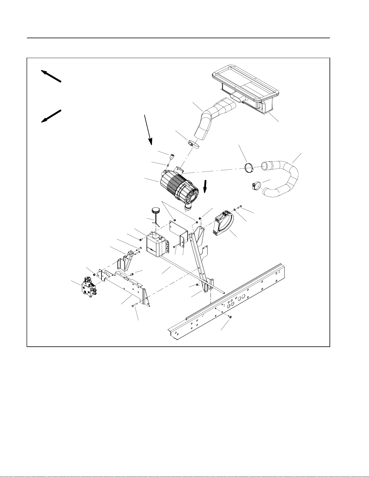
Air Filter System
RIGHT
FRONT
8
12 to 15 in--lb
27
(1.4 to 1.6 N--m)
13
26
13
12
24
23
11
14
Vacuator
Direction
18
18
25
16
10
15
20
6
1
19
17
9
7
21
22
4
1. Battery support
2. Bracket
3. Flange head screw (8 used)
4. Flange nut (8 used)
5. Support bracket
6. Cap screw (4 used)
7. Flange nut (4 used)
8. Fan drive manifold
9. Air cleaner strap
5
6
10. Cap screw (2 used)
11. Air cleaner assembly
12. Service indicator
13. Hose clamp
14. Hose clamp
15. Flat washer (2 used)
16. Coolant reservoir
17. Reservoir bracket
18. Flange nut (8 used)
2
3
Figure 1
19. Cap screw (2 used)
20. Flange head screw (4 used)
21. Flange head screw (2 used)
22. Hose
23. Adapter
24. Air cleaner hose
25. Reservoir cap
26. Plenum
27. Air intake hose
Reelmaster 7000Page 3 -- 4Kubota Diesel Engine
Page 21
Removal (Fig. 1)
1. Park machineon a levelsurface, lower cuttingunits,
stop engine, apply parking brake and remove key from
the ignition switch.
2. Raise and support hood.
3. Remove air cleaner components as needed using
Figure 1 as a guide.
Installation (Fig. 1)
IMPORTANT: Any leaks in the air filter system will
causeserious enginedamage. Make sure that allair
cleaner components are in good condition and are
properly secured during assembly.
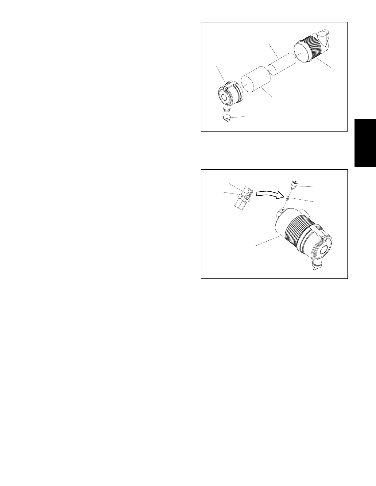
1. Assemble air filter systemusing Figure 1as aguide.
A. If service indicator (item 12) was removed from
air cleaner housing, apply thread sealant to adapter
threads before installing adapter and indicator to
housing. Install adapter so that grooves in adapter
hex and adapter filter element are installed toward
serviceindicator (Fig.3).Torqueindicator from12 to
15 in--lb (1.4 to 1.6 N--m).
4
5
1. Air cleaner housing
2. Safety filter element
3. Air filter element
5
4
2
3
Figure 2
4. Air cleaner cover
5. Vacuator valve
1
Kubota
Diesel Engine
2
3
B. Orientate vacuator valve on air cleaner cover toward ground.
C. Installaircleanersoaircleanerstrap(item9)isas
close as possible to air cleaner cover.
D. Make sure that air cleaner hose (item 24) does
notcontact engine valve coveror other engine components.Tomodify clearance, moveand/or rotateair
cleaner body in air cleaner strap. Verify that tabs in
strap mesh fully with slots in air cleaner body.
2. After air cleaner installation is completed, lower and
secure hood.
1
1. Air cleaner assembly
2. Service indicator
3. Adapter
Figure 3
4. Groove
5. Filter element
Reelmaster 7000 Page 3 -- 5 Kubota Diesel Engine
Page 22
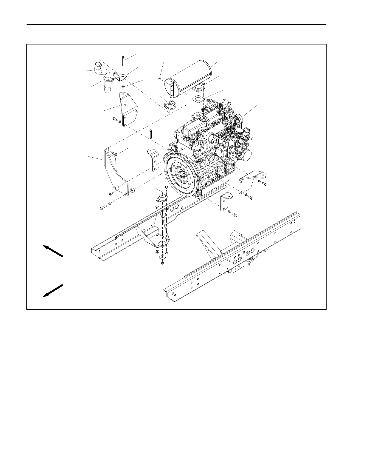
Exhaust System
8
13
12
1
5
3
10
14
7
4
11
6
2
9
RIGHT
FRONT
1. Muffler
2. Flange head screw (2 used)
3. Flange head screw (4 used)
4. Muffler clamp
5. Tailpipe
Figure 4
6. RH engine mount
7. Flat washer
8. Cap screw
9. Muffler bracket
10. Muffler gasket
11. Engine
12. Muffler bracket
13. Flange nut (2 used)
14. Muffler clamp
Reelmaster 7000Page 3 -- 6Kubota Diesel Engine
Page 23
Removal (Fig. 4)
CAUTION
The muffler and exhaust pipe may be hot. To
avoid possible burns, allow the engine and exhaust system to cool before working on themuffler.
Installation (Fig. 4)
IMPORTANT: If exhaust studs were removed from
engine cylinder head, thoroughly clean threads in
head and apply Loctite #277 (or equivalent) to stud
threads before installing studs into head.
NOTE: Makesure mufflerflange and exhaustmanifold
sealing surfaces are free of debris or damage that may
prevent a tight seal.
1. Park machineon a levelsurface, lower cuttingunits,
stop engine, engage parking brake and remove key
from the ignition switch.
2. Raise and support hood.
3. Remove muffler and/or muffler bracket from the en-
gine as necessary using Figure 4 as a guide.
1. Install new exhaust gasket if original gasket is damaged or torn.
IMPORTANT: Failure to follow the suggested mufflerfastenersequence may resultin premature muffler failure.
2. Installexhaustsystemcomponents to theengineusingFigure4 asa guide. Handtighten allexhaustsystem
fasteners before fully tightening any fastener.
3. Tailpipeshouldhaveequalclearancebetweenframe
and engine after installation.
4. Afterexhaustsystem installation iscompleted,lower
and secure hood.
Kubota
Diesel Engine
Reelmaster 7000 Page 3 -- 7 Kubota Diesel Engine
Page 24
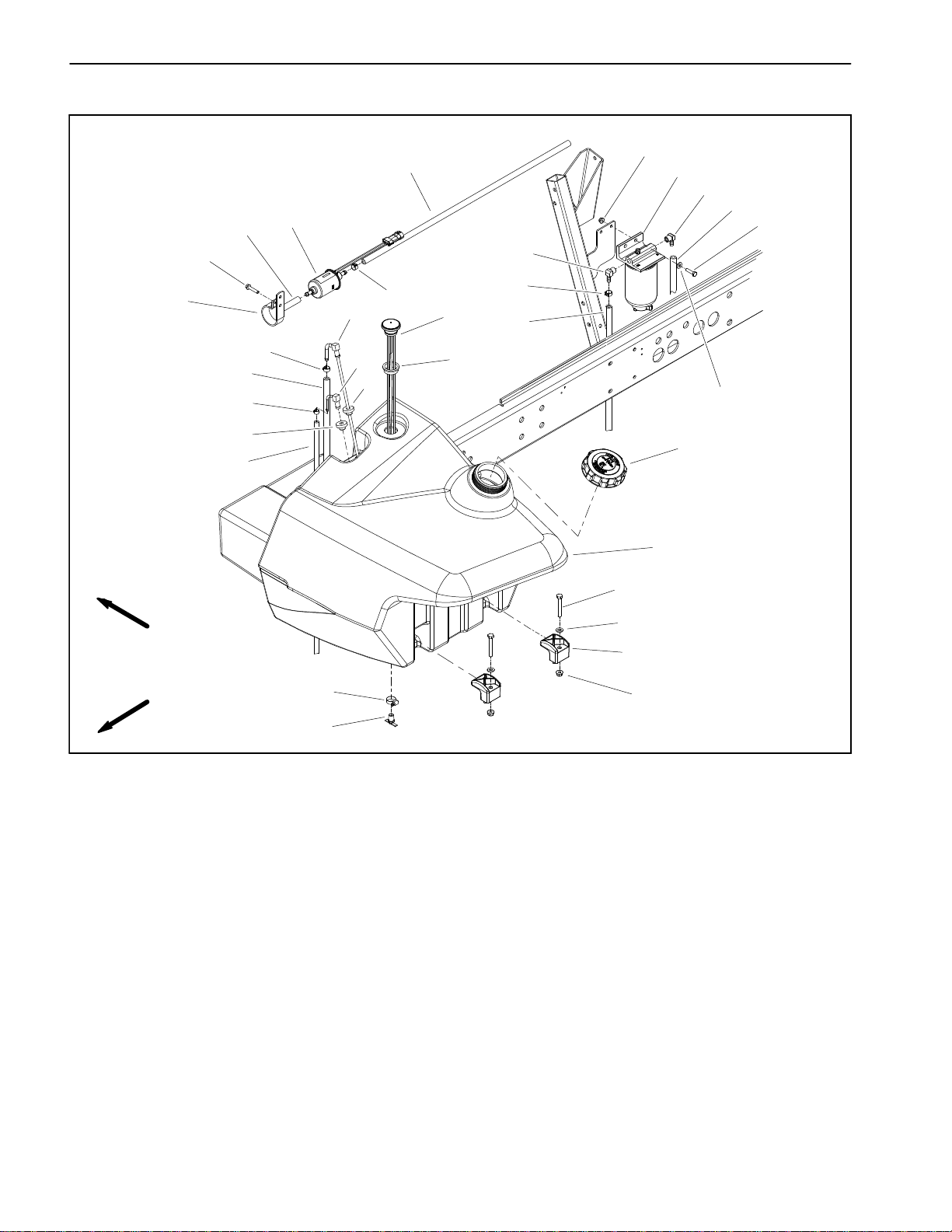
Fuel System
14
19
16
20
21
16
13
3
18
21
15
RIGHT
FRONT
8
8
1
8
3
4
7
2
7
24
17
25
23
6
5
9
10
22
11
26
12
27
1. Fuel suction tube
2. Fuel line clamp (2 used)
3. Fuel hose (supply)
4. Return fitting
5. Fuel hose (return)
6. Fuel tank cap
7. Bushing (2 used)
8. Hose clamp (6 used)
9. Fuel tank
Figure 5
10. Cap screw (2 used)
11. Clamp (2 used)
12. Flange nut (2 used)
13. Fuel pump
14. Washer head screw
15. Fuel pump bracket
16. Fuel hose (supply)
17. Fuel hose (supply)
18. Cap screw (2 used)
19. Flange nut (2 used)
20. Fuel/water separator
21. Elbow fitting (2 used)
22. Flat washer (2 used)
23. Flat washer (2 used)
24. Fuel gauge
25. Grommet
26. Hose clamp
27. Draincock
Reelmaster 7000Page 3 -- 8Kubota Diesel Engine
Page 25
Fuel Tank Removal (Fig. 5)
DANGER
Because diesel fuel is flammable, use caution
when storing or handling it. Do not smoke while
filling the fuel tank. Do not fill fuel tank while engine is running, hot or when machine is in an enclosed area. Always fill fuel tank outside and
wipeupany spilled dieselfuelbefore startingthe
engine. Store fuel in a clean, safety--approved
container and keep cap in place. Use diesel fuel
for the engine only; not for any other purpose.
Check Fuel Lines and Connections
Check fuel lines and connections as recommended in
theTractionUnitOperator’sManual.Check linesfordeterioration, damage, leaking or loose connections. R eplace hoses, clamps and connections as necessary.
Drain and Clean Fuel Tank
Drain and clean the fuel tank periodically as recommended in the Traction Unit Operator’s Manual. Also,
drainand clean thefuel tankif the fuelsystem becomes
contaminatedor if themachine is tobe stored for an extended period. To clean fuel tank, flush tank out with
cleandieselfuel.Make suretankisfree ofcontaminates
and debris.
1. Park machineon a levelsurface, lower cuttingunits,
stop engine, engage parking brake and remove key
from the ignition switch.
2. Disconnectfuelhosesfromthe suctionandreturnfittings in top of tank.
3. Use draincock on bottom of tank to empty fuel tank
into a suitable container.
4. Remove fuel tank from machine using Figure 5 as a
guide.
Fuel Tank Installation (Fig. 5)
1. Install fuel tank to frame using Figure 5 as a guide.
2. Connect fuel hoses to the suction and return fittings
in top of tank.
3. Makesurethatdraincockonbottomoftankisclosed.
4. Fill fuel tank with clean fuel.
Kubota
Diesel Engine
Reelmaster 7000 Page 3 -- 9 Kubota Diesel Engine
Page 26
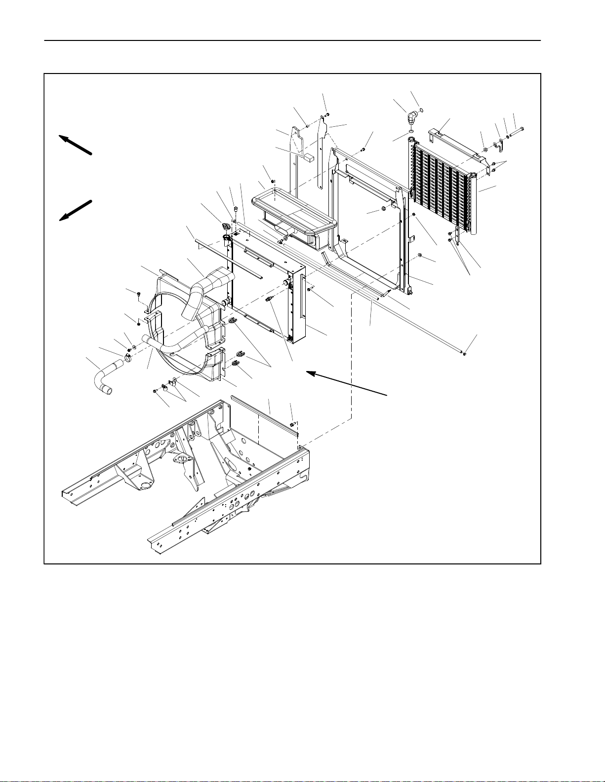
Radiator
RIGHT
FRONT
13
40
18
15
18
17
12
14
28
10
42
39
26
46
25
24
28
23
15
7
29
35
1
31
33
32
30
3
43
2
11
5
37
38
6
3
15
22
27
43
10
36
17
41
20
34
19
21
16
4
44
8
9
45
9to11ft--lb
(12.3 to 14.9 N--m)
1. 90ohydraulic fitting (2 used)
2. Oil cooler
3. Flange nut (4 used)
4. Radiator mount
5. Bulb seal
6. Air cleaner hose
7. Plenum
8. Radiator
9. Hose
10. Hose clamp (3 used)
11. Radiator cap
12. Upper radiator shroud
13. Clamp (4 used)
14. Upper radiator hose
15. Flange nut (12 used)
16. Temperature sender
Figure 6
17. Flat washer (8 used)
18. Flange head screw (11 used)
19. Rubber grommet (2 used)
20. Rubber grommet
21. Flange head screw (4 used)
22. Flange nut (4 used)
23. Foam seal (2 used)
24. Recirculation barrier (2 used)
25. Recirculation barrier bracket (2 used)
26. Screw (2 used)
27. Oil cooler mount plate (2 used)
28. Flange head screw (9 used)
29. O--ring
30. Clamp (2 used)
31. Cap screw (2 used)
32. Washer (2 used)
33. Oil cooler top bracket
34. Bulb seal
35. O--ring
36. R--clamp (2 used)
37. Bushing
38. Elbow fitting
39. Reservoir hose
40. Lower radiator hose
41. Lower radiator shroud
42. Pipe plug
43. Flange head screw (8 used)
44. Flange head screw (4 used)
45. Bulb seal
46. Spacer
Reelmaster 7000Page 3 -- 10Kubota Diesel Engine
Page 27
Removal (Fig. 6)
1. Park machineon a levelsurface, lower cuttingunits,
stop engine, engage parking brake and remove key
from the ignition switch.
2. Removehoodfromthemachine(seeHoodRemoval
inthe Serviceand Repairs section of Chapter7 -- Chassis).
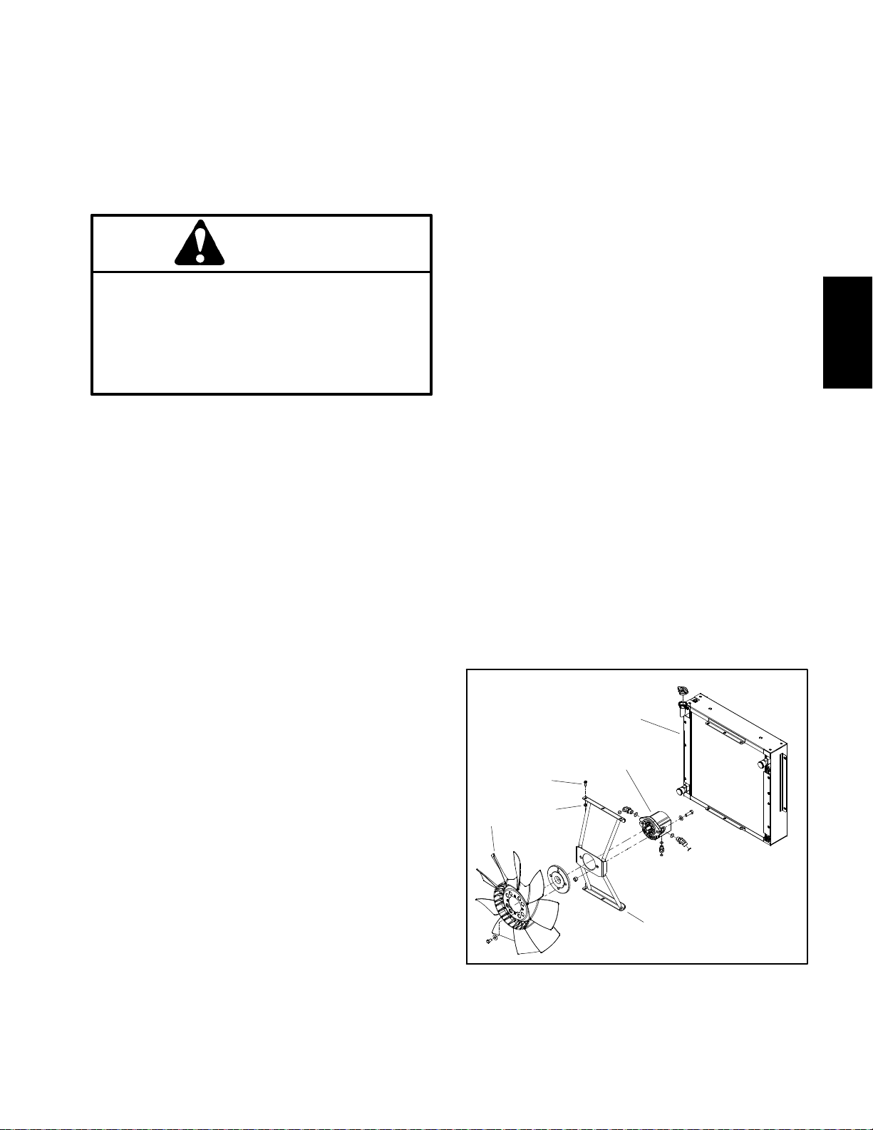
CAUTION
Do not open radiator cap or drain coolant if the
radiator or engine is hot. Pressurized, hot coolant can escape and cause burns.
Ethylene--glycol antifreeze is poisonous. Dispose of coolant properly or store it in a properly
labeled container away from children and pets.
3. Remove radiator cap. Drain radiator into a suitable
container using the radiator draincock.
4. Disconnectupper andlowerhoses fromtheradiator.
5. Remove air cleaner hose (item 6).
2. Carefully position radiator and recirculation barriers
(items24 and 25) to theradiator mount.Secure radiator
and barriers in place with four (4) flange head screws
and flange nuts.
3. Positionlower radiator shroudandfan motor bracket
assembly to the radiator. Make sure that hydraulic
hoses are correctly positioned in grommets in lower radiator shroud.
4. Secure fan motor bracket to radiator withsix (6) cap
screws and flange nuts (Fig. 7).
5. Secure lower radiator shroud to radiator with removed fasteners.
6. Position upper radiator shroud to lower radiator
shroud and radiator.Secure shrouds with removed fasteners.Make sure that clearance between shrouds and
fan is at least 0.180” (4.6 mm) at all points.
7. Connectreservoir hose(item 39)to theradiator vent
tube.
8. Connect upper and lower hoses to the radiator.
9. Install plenum (item 7) to radiator mount and secure
with flange head screws and flange nuts.
Kubota
Diesel Engine
6. Removefour (4)flange headscrewsand flangenuts
that secure plenum (item 7) to radiator mount. Remove
10.Install aircleaner hose(item 6)to theair cleaner and
plenum.
plenum.
11.Fill radiator with coolant.
7. Disconnectreservoirhose(item39)from theradiator
vent tube.
12.Install hoodon the machine(see HoodInstallation in
the Service and Repairs section of Chapter 7 -- C has-
8. Detach upper radiator shroud from the radiator and
sis).
lower radiator shroud. Remove upper shroud from machine.
9. Removefasteners thatsecure lowerradiator shroud
6
to radiator.
10.Remove six (6) cap screws and flange nuts that se-
cure fan motor bracket to radiator (Fig. 7).
11.Position lowerradiatorshroud and fanmotorbracket
4
1
5
3
assembly away from radiator.
12.Remove four(4) flangeheadscrews andflange nuts
securingtheradiatorandrecirculationbarriers(items24
and25) totheradiator mount.Carefully removebarriers
and radiator from the machine.
2
13.Plug all radiator and hose openings to prevent con-
tamination.
Installation (Fig. 6)
1. Removeplugs placed in radiator andhose openings
1. Fan
2. Fan motor bracket
3. Fan motor
Figure 7
4. Cap screw (6 used)
5. Flange nut (6 used)
6. Radiator
during the removal procedure. Make sure that radiator
draincock is closed.
Reelmaster 7000 Page 3 -- 11 Kubota Diesel Engine
Page 28
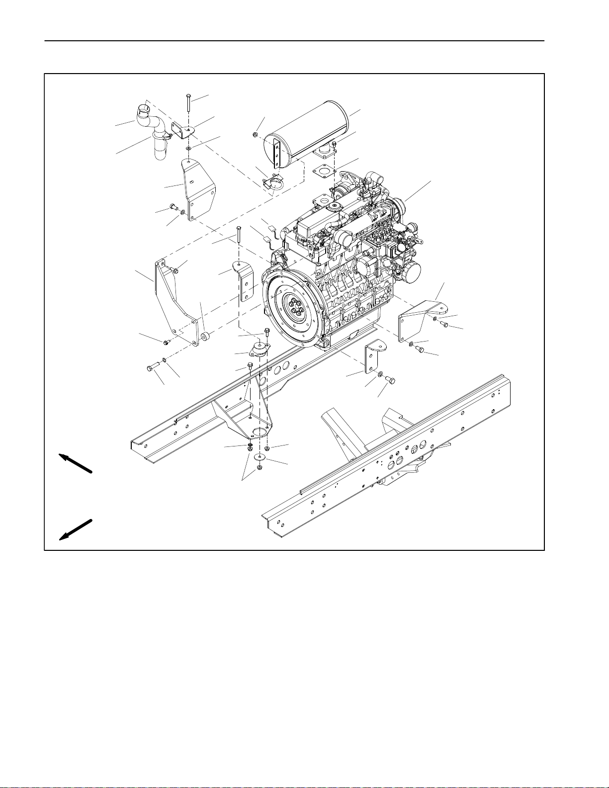
Engine
29
31
5
30
12
1
3
33
20
4
22
9
6
18
21
28
17
7
10
8
19
25
24
2
10
17
11
26
32
34
14
15
23
18
16
27
12
RIGHT
FRONT
1. Muffler
2. Flange head screw
3. Flange head screw (4 used)
4. Muffler clamp
5. Tailpipe
6. RH rear engine mount
7. Cap screw (3 used)
8. RH front engine mount
9. Engine
10. Flange head screw (10 used)
11. Engine mount (4 used)
12. Flange nut (15 used)
13
12
Figure 8
13. Rebound washer (4 used)
14. LH front engine mount
15. Lock washer (4 used)
16. Cap screw (4 used)
17. Lock washer (5 used)
18. Cap screw (5 used)
19. LH rear engine mount
20. Muffler bracket
21. Ground wire harness
22. Muffler gasket
23. Cap screw
24. Lock washer
25. Spacer (2 used)
26. Hardened washer (2 used)
27. Lock washer
28. Alternator wire harness
29. Cap screw
30. Flat washer
31. Muffler bracket
32. Flange head screw
33. Muffler clamp
34. Cap screw (2 used)
Reelmaster 7000Page 3 -- 12Kubota Diesel Engine
Page 29
Engine Removal (Fig. 8)
1. Park machineon a levelsurface, lower cuttingunits,
stop engine, engage parking brake and remove key
from the ignition switch.
2. Removehoodfromthemachine(seeHoodRemoval
inthe Serviceand Repairs section of Chapter7 -- Chassis).
3. Remove battery cover. Disconnect negative battery
cable first and then positive battery cable.
CAUTION
Do not open radiator cap or drain coolant if the
radiator or engine is hot. Pressurized, hot coolant can escape and cause burns.
Ethylene--glycol antifreeze is poisonous. Dispose of coolant properly, or store it in a properly
labeled container away from children and pets.
4. Drain coolant from radiator into a suitable container
(seeRadiatorRemovalinthissection).Disconnectcoolant hoses from the radiator.
5
2
3
1. Engine run solenoid
2. Throttle cable
3. Cable clamp
1
4
Figure 9
4. Cable swivel
5. Fuel supply hose
1
Kubota
Diesel Engine
3
CAUTION
The exhaust system may be hot. To avoid possibleburns, allow the exhaust system to coolbefore working on or near the muffler.
5. Remove exhaust system from engine (see Exhaust
System Removal in this section).
6. Remove air cleaner system from engine (see Air
Cleaner Removal in this section).
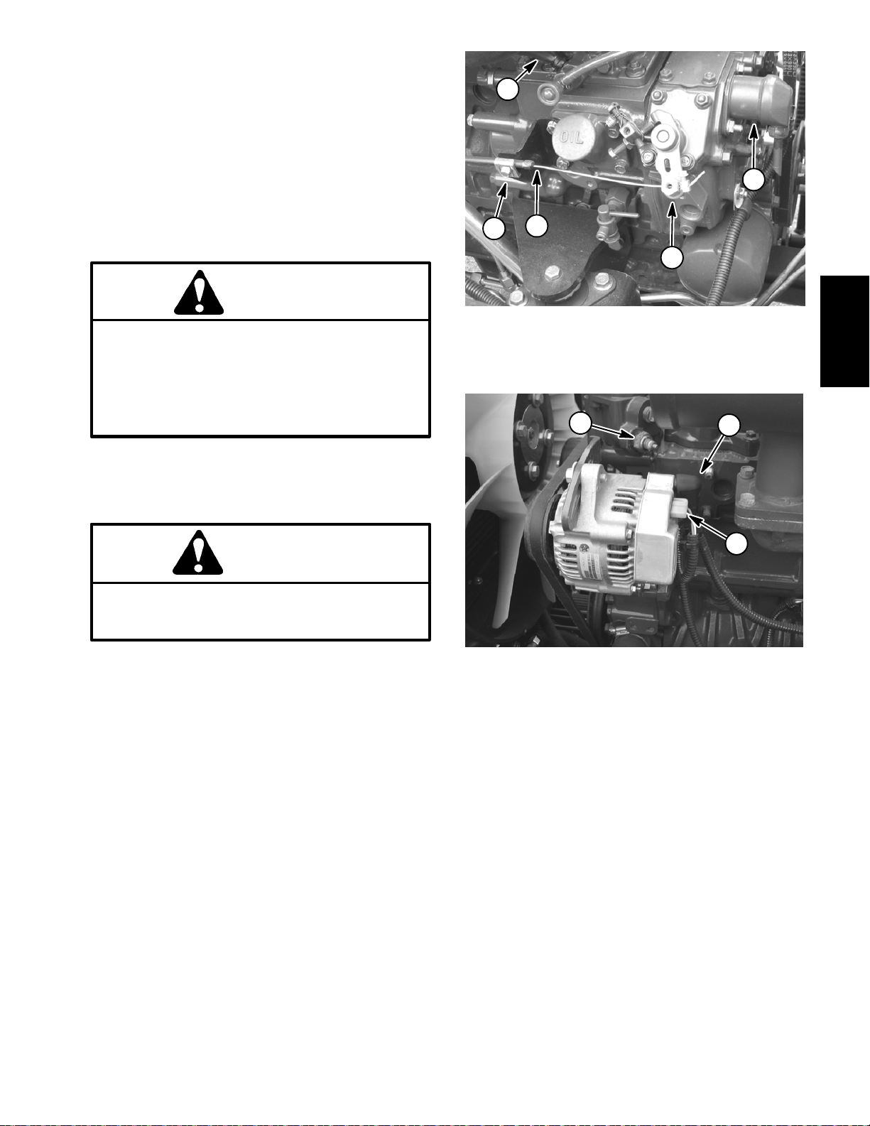
7. Note location of cable ties used to secure wire har-
ness. Disconnect wire harness connectors from the following engine components:
A. The engine run solenoid (Fig. 9).
B. The temperature sender (Fig. 10).
C. The alternator (Fig. 10).
D. The glow plug connection.
E. Wireharness connectorfrom engineground har-
ness.
F. The electric starter motor.
2
Figure 10
1. Temperature sender
2. Harness connector
3. Battery cable
8. Disconnect fuel supply hose from injection pump
(Fig.9).Capfuelhoseandinjectorpumpfuelinlettoprevent contamination.
9. Remove throttle cable from engine (Fig. 9):
A. Removelocknut thatsecuresthrottle cableswiv-
el to speed control lever.
B. Loosen cable clamp and remove throttle cable
from under clamp.
C. Position throttle cable away from the engine.
10.Remove fasteners that secure the upper radiator
shroud to the lower shroud and radiator (see Radiator
Removalinthissection).Removeupperradiator shroud
from machine.
G. Low oilpressureswitchlocatedonalternator side
of engine (above electric starter).
Reelmaster 7000 Page 3 -- 13 Kubota Diesel Engine
Page 30
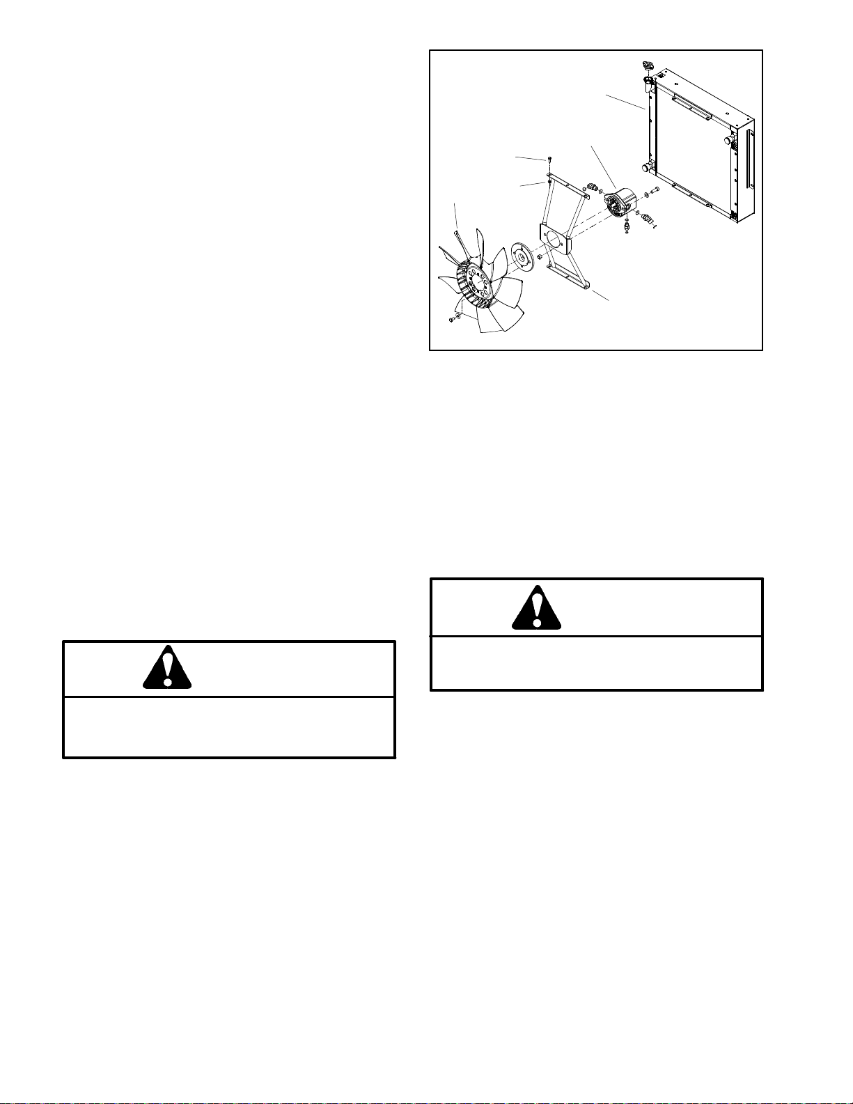
11.Remove fan motor and fan assembly (Fig. 11).
A. To prevent contamination of hydraulic system,
thoroughly clean exterior of fan motor and fittings.
B. Disconnecthydraulic hosesfrom coolingfan mo-
tor.Putcaps orplugsonfittings andhosestoprevent
contamination. Label hydraulic lines for proper assembly.
C. Remove six (6) cap screws and flange nuts that
secure fan motor bracket to radiator.
D. Carefullyremove fanmotor,fan andmotorbracket assembly from machine.
IMPORTANT: The hydraulic pump assembly canremain in machine during engine removal. Toprevent
pump assembly from shifting or falling, make sure
to support pump assembly before pump mounting
fasteners are removed.
12.Support hydraulic pump assembly.Remove fasten-
ers that secure piston (traction) pump assembly to engine(see Piston (Traction) PumpAssembly Removal in
theService and Repairssection of Chapter4 -- Hydraulic System).
6
3
4
1
5
2
Figure 11
1. Fan
2. Fan motor bracket
3. Fan motor
4. Cap screw (6 used)
5. Flange nut (6 used)
6. Radiator
2. Make sure that all parts removed from the engine
duringmaintenanceor rebuildingareinstalled totheengine.
13.Make sureall cableties securingthe wiringharness,
fuellines or hydraulic hoses to the engineare removed.
14.Connect lift or hoist to the lift tabs on engine.
15.Remove flange nuts, rebound washers and cap
screws that secure the engine mount brackets to the
rubber engine mounts.
CAUTION
One person should operate lift or hoist while a
second person guides the engine out of the machine.
IMPORTANT: Make sure to not damage the engine,
fuel lines, hydraulic lines, electrical harness or other parts while removing the engine.
16.Carefully raise engine from the machine.
17.Ifnecessary,removeenginemountsfrom the engine
using Figure 8 as a guide.
Engine Installation (Fig. 8)
3. Ifremoved,installengine mountstotheengineusing
Figure 8 as a guide.
4. Connect lift or hoist to the lift tabs on engine.
CAUTION
One person should operate lift or hoist while a
second person guides the engine into the machine.
IMPORTANT: Make sure to not damage the engine,
fuel lines, hydraulic lines, electrical harness or other parts while installing the engine.
5. Carefully lower engine into the machine.
6. Align engine to the rubber engine mounts and hydraulic pump input shaft. Secure engine to engine
mounts with cap screws, rebound washers and flange
nuts.
7. Securehydraulicpumpassemblytoengine(seePiston(Traction)Pump AssemblyInstallationintheService
and Repairs section of Chapter 4 -- Hydraulic System).
1. Locatemachine ona levelsurfacewith keyremoved
from the ignition switch. Chock wheels to keep the machine from moving.
Reelmaster 7000Page 3 -- 14Kubota Diesel Engine
Page 31

8. Install fan motor and fan assembly (Fig. 11).
C. The alternator (Fig. 10).
A. Carefullypositionfanmotor,fanandmotorbracket assembly to radiator.
B. Secure fan motor bracket to radiator with six (6)
cap screws and flange nuts.
C. Remove caps and plugs placed in hoses and fittings during removal to prevent contamination.
D. Connect hydraulic hoses to cooling fan motor
(see Hydraulic Hose and Tube Installation in the
GeneralInformationsectionofChapter4 -- Hydraulic
System).
9. Position upperradiator shroud to the radiator.Secureshroud to the radiator and lower radiatorbracket with
removedfasteners(seeRadiator Installationinthissection).Makesure thatclearancebetweenshroud andfan
is at least 0.180” (4.6 mm) at all points.
10.Connect throttle cable to engine (Fig. 9):
A. Secure throttle cable swivel to speed control le-
ver with lock nut.
B. Place throttle cable under cable clamp.
C. Adjust throttle cable position in cable clamp so
that engine governor lever contacts the high speed
stop boltat the same time that the throttle levercontacts the end of the slot in the control console.
D. Tighten cable clamp to secure throttle cable.
11.Remove caps from fuel hose and injector pump fuel
inlet that were placed during engine removal to prevent
contamination. Connect fuel supply hose to injection
pump (Fig. 9). Secure hose with hose clamp.
12.Connect wire harness connectors to the following
engine components:
A. The engine run solenoid (Fig. 9).
B. The temperature sender (Fig. 10).
D. The glow plug connection.
E. Wire harness connector to engine ground har-
ness.
F. Theelectricstarter.TorquenutatstarterB+termi-
nal from 70 to 86 in--lb (7.9 to 9.7 N--m).
G. Low oilpressureswitchlocatedonalternator side
of engine (above electric starter).
13.Using notes taken during engine removal, secure
wires with cable ties in proper locations.
14.Install air cleaner assembly to the engine (see Air
Cleaner Installation in this section).
15.Installexhaustsystemtomachine(seeExhaustSystem Installation in this section).
16.Connect coolanthosesto theradiator.Make sureradiatordraincockisclosed.Fillradiatorandreservoirwith
coolant.
17.Check position of wires, fuel lines, hydraulic hoses
andcables for proper clearance withrotating, high temperature and moving components.
18.Connect positive battery cable first and then negative battery cable. Secure battery cover to machine.
19.Check and adjust engine oil level as needed.
20.Check and adjust hydraulic oil level as needed.
21.Bleed fuel system.
22.Operate hydraulic controls to properly fill hydraulic
system (see Charge Hydraulic System in the Service
andRepairs sectionof Chapter4 -- HydraulicSystems).
23.Install hoodon the machine(see HoodInstallation in
the Service and Repairs section of Chapter 7 -- C hassis).
Kubota
Diesel Engine
Reelmaster 7000 Page 3 -- 15 Kubota Diesel Engine
Page 32

Pump Adapter Plate
RIGHT
1
2
FRONT
29 to 33 ft--lb
(40to44N--m)
3
Boss
Loctite #242
5
6
4
1. Bolt
2. Lock washer
3. Flywheel plate
4
7
Figure 12
4. Hardened washer (14 used)
5. Spring coupler
6. Bolt (6 used)
7. Cap screw (8 used)
Reelmaster 7000Page 3 -- 16Kubota Diesel Engine
Page 33

Coupler Removal (Fig. 12)
NOTE: The hydraulic pump assembly needs to be re-
moved from engine before coupler can be removed.
1. If engine is in machine, remove hydraulic pump as-
sembly(seePiston(Traction)PumpRemovalintheService and Repairs section of Chapter 4 -- Hydraulic
System).
2. Remove flywheel plate and spring coupler from en-
gine using Figure 12 as a guide.
Coupler Installation (Fig. 12)
1. Position spring coupler to engine flywheel and align
mounting holes. Make sure that coupling hub is away
from engine flywheel (Fig. 13).
2. Apply Loctite #242 (orequivalent) to threads of bolts
(item6).Securecouplertoflywheel withsix(6)boltsand
hardened washers. Torque bolts in a crossing pattern
from 29 to 33 ft--lb (40 to 44 N--m).
3. Position flywheel plate to engine. Make sure that
boss on plate is orientated down. Secure flywheel plate
with cap screws (item 7) and hardened washers using
a crossing pattern tightening procedure.
Engine Side Hydraulic
Pump Side
Figure 13
1. Coupler
2. Coupler hub
3. Engine flywheel
1
2
3
Kubota
Diesel Engine
4. If engine is in machine, install hydraulic pump as-
sembly (see Piston (Traction) Pump Installation in the
Service and Repairs section of Chapter 4 -- Hydraulic
System).
Reelmaster 7000 Page 3 -- 17 Kubota Diesel Engine
Page 34

This page is intentionally blank.
Reelmaster 7000Page 3 -- 18Kubota Diesel Engine
Page 35

Table of Contents
Chapter 4
Hydraulic System
SPECIFICATIONS 3............................
GENERAL INFORMATION 4.....................
Operator’s Manual 4..........................
Towing Traction Unit 4.........................
Check Hydraulic Fluid 4.......................
Relieving Hydraulic System Pressure 5..........
Traction Circuit Component Failure 5............
Hydraulic Hoses 6............................
Hydraulic Hose and Tube Installation 7..........
Hydraulic Fitting Installation 8..................
HYDRAULIC SCHEMATIC 10....................
HYDRAULIC FLOW DIAGRAMS 12...............
Traction Circuit: Mow Speed (4WD) 12..........
Traction Circuit: Transport Speed (2WD) 14......
Lower Cutting Units 16........................
Raise Cutting Units 18.........................
Mow Circuit 20...............................
Steering Circuit 22............................
Engine Cooling Fan Circuit 24..................
SPECIAL TOOLS 26............................
TROUBLESHOOTING 30........................
TESTING 36...................................
Traction Circuit Charge Pressure Test 38.........
Traction Circuit Relief Pressure Test 40..........
Traction Circuit Reducing Valve (PR)
Pressure Test 42............................
Rear Traction Circuit Relief (RV) Pressure Test 44
Piston (Traction) Pump Flow Test 46............
Mow Circuit Pressure Test 48...................
Mow Circuit Relief Pressure Test 50.............
Cutting Unit Motor Case Drain Leakage Test 52...
Gear Pump P1 and P2 Flow (Mow Circuits) Test 54
Steering Circuit Relief Pressure Test 56..........
Steering Cylinder Internal Leakage 58...........
Lift/Lower Circuit Relief Pressure Test 60........
Gear Pump P3 Flow (Steering and Lift/Lower
Circuits) Test 62.............................
Cooling Fan Circuit Test 64.....................
Gear Pump P4 Flow (Cooling Fan Circuit) Test 66.
ADJUSTMENTS 68.............................
Adjust Control Manifold Relief Valves 68.........
SERVICE AND REPAIRS 69.....................
General Precautions for Removing and
Installing Hydraulic System Components 69....
Check Hydraulic Lines and Hoses 70............
Flush Hydraulic System 71.....................
Filtering Closed--Loop Traction Circuit 72........
Charge Hydraulic System 73...................
Gear Pump 74................................
Gear Pump Service 76........................
Piston (Traction) Pump 78.....................
Piston (Traction) Pump Service 80..............
4WD/2WD and Filtration/Charge Control
Manifolds 82.....
4WD/2WD Control Manifold Service 84..........
Filtration/Charge Control Manifold Service 86.....
Control Manifold Cartridge Valve Service 87......
Rear Axle Motor 88...........................
Front Wheel Motors 90........................
Rear Axle and Front Wheel Motor Service 92.....
Cutting Reel Motor 93.........................
Cutting Reel Motor Service 94..................
Mow Control Manifold 98......................
Mow Control Manifold Service 100..............
Steering Control Valve 102.....................
Steering Control Valve Service 104..............
Steering Cylinder 106.........................
Steering Cylinder Service 108..................
Engine Cooling Fan Motor 110..................
Engine Cooling Fan Motor Service 112..........
Fan Control Manifold 114......................
Fan Control Manifold Service 116...............
Lift Control Manifold 118.......................
Lift Control Manifold Service 120................
Lift Circuit Junction Manifold 122................
Front Lift Cylinders 124........................
Rear Lift Cylinders 126........................
Lift Cylinder Service 128.......................
Hydraulic Reservoir 130.......................
Hydraulic Oil Cooler 132.......................
EA TON MODEL 72400 SERVO CONTROLLED PIS-
TON PUMP REPAIR INFORMATION
EATON MODEL 74318 and 74348 PISTON MOTORS:
FIXED DISPLACEMENT, VALVE PLATE DESIGN
REPAIR INFORMATION
SAUER--DANFOSS STEERING UNIT TYPE OSPM
SERVICE MANUAL
.......
....................
System
Hydraulic
Reelmaster 7000 Hydraulic SystemPage 4 -- 1
Rev. A
Page 36

This page is intentionally blank.
Reelmaster 7000Hydraulic System Page 4 -- 2
Page 37

Specifications
Item Description
Piston (Traction) Pump Eaton variable displacement piston pump
Maximum Displacement (per revolution) 2.48 in
System Relief Pressure: Forward 5000 PSI (345 bar)
System Relief Pressure: Reverse 5000PSI (345 bar)
Charge Pressure 207 PSI (14.3 bar)
Front Wheel Motors Eaton fixed displacement piston motors
Displacement (per revolution) 2.01 in
Rear Axle Motor Eaton fixed displacement piston motor
Displacement (per revolution) 2.48 in
Gear Pump Casappa 4 section, positive displacement gear type pump
Section P1/P2 Displacement (per revolution) 1.03in
Section P3/P4 Displacement (per revolution) 0.56 in
Steering Control Valve Sauer--Danfoss Steering Unit, Series OSPM
Displacement (per revolution) 6.1 in
Steering Circuit Relief Pressure 1050 PSI (72 bar)
Lift/Lower Circuit Relief Pressure 1700 PSI (117 bar)
Cutting Unit Motors Casappa Gear Motor
Displacement (per revolution) 1.61 in
(Model 72400)
3
(40.6 cc)
(Model 74315)
3
(32.9 cc)
(Model 74318)
3
(40.6 cc)
3
(16.85 cc)
3
(9.16 cc)
3
(100 cc)
3
(26.5 cc)
System
Hydraulic
Cutting Unit Circuit Relief Pressure 3000 PSI (207 bar)
Engine Cooling Fan Motor Casappa Gear Motor
Displacement (per revolution) 0.51 in
Engine Cooling Fan Circuit Relief Pressure 3000 PSI (207 bar)
Hydraulic Filters Spin--on cartridge type
In--line S uction Strainer 100 mesh (in reservoir)
Hydraulic Reservoir Capacity 8.25 U.S. Gallons (31.3 Liters)
Hydraulic Oil See Traction Unit Operator’s Manual
3
(8.4 cc)
NOTE: The pressure specifications listed above are
component settings. When using pressure gauges to
measurecircuit pressures,values may bedifferent than
these specifications. See the Testing section of this
chapterfor hydraulic test proceduresand expected test
results.
Reelmaster 7000 Hydraulic SystemPage 4 -- 3
Page 38

General Information
Operator’s Manual
The Operator’s Manual provides information regarding
the operation, general maintenance and maintenance
intervals for your Reelmaster machine. Refer to that
publicationforadditional information whenservicingthe
machine.
Towing Traction Unit
IMPORTANT: If towing limits are exceeded, severe
damage to the piston pump may occur.
If it becomes necessary to tow (or push) the machine,
tow (or push) in a forward direction only, at a speed
below3 mph(4.8 kph) andfor adistance lessthan 1/4
mile (0.4 km). The piston (traction) pump is equipped
witha bypass valve thatneeds to be turned90
ing(Fig.1).Donotturnbypassvalvewhenengineisrunning.
o
fortow-
1
See Traction Unit Operator’s Manual for additional towing procedures.
IMPORTANT: If the machine must be pushed or
towed in a reverse direction, the check valve in the
4WD/2WD control manifold must be bypassed. To
bypass this check valve, connect a hydraulic hose
between the reverse traction pressure test port and
the 4WD/2WD control manifold test port (G). Toro
part numbers 95--8843 (hydraulic hose), 95--0985
(coupler fitting) (2 required) and 340--77 (hydraulic
fitting) (2 required) are needed for this connection.
Check Hydraulic Fluid
The Reelmaster 7000 hydraulic systems are designed
to operate on anti --wear hydraulic fluid. The reservoir
holdsapproximately8.25U.S.gallons (31.3 liters)ofhydraulic fluid. Check level of hydraulic fluid daily.
Figure 1
1. Bypass valve location
1
2
Figure 2
1. Hydraulic reservoir 2. Reservoir cap
Reelmaster 7000Hydraulic System Page 4 -- 4
Page 39

Relieving Hydraulic System Pressure
Beforedisconnecting orperforming any workon thehydraulic system, all pressure in the hydraulic system
mustbe relieved.Parkmachineonalevelsurface,lower
cutting units fully,stop engine and apply parking brake.
To relieve hydraulic pressure in traction circuit, move
tractionpedal to bothforward andreverse directions.To
relieve hydraulic pressure in steering circuit, rotate
steering wheel in both directions.
Traction Circuit Component Failure
The traction circuit on Reelmaster 7000 machines is a
closed loop system that includes the piston (traction)
pump, two (2) front wheel motors and the rear axle motor.If a component in the traction circuit should fail, debris and contamination from the failed component will
circulatethroughoutthetraction circuit.Thiscontamination can damage other components in the circuit so it
must be removed to prevent additional component failure.
The recommended method of removing traction circuit
contamination would be to temporarily install the Toro
high flow hydraulic filter (see Special Tools in this chapter) into the circuit. This filter should be used when connecting hydraulic test gauges in order to test traction
circuitcomponentsorafterreplacing a failedtractioncircuit component (e.g. traction (piston) pump or wheel
motor). The filter will ensure that contaminates are removedfromtheclosedloop andthus,donotcauseadditional component damage.
Once the Toro high flow hydraulic filter kit has been
placedin the circuit,raise and support the machinewith
Systempressureinmow circuit isrelievedwhen the cuttingunits are disengaged(PTO switchin OFF position).
To relieve hydraulicpressure in lift circuit, fullylower the
cutting units to the ground. Turn ignition switch to OFF.
all drive wheels off the ground. Then, operate the tractioncircuit toallow oil flowthroughout thecircuit. The filter will remove contamination from the traction circuit
duringoperation. Because the Torohigh flowfilter is bi-directional, the traction circuit can be operated in both
the forward and reverse direction. The filter should be
removed from the machine after contamination has
been removed from the traction circuit. See Filtering
Closed--LoopTractionCircuitintheServiceandRepairs
section of this chapter for additional information on using the Toro high flow hydraulic filter.
Thealternativetousingthe Torohighflow hydraulic filter
kit after a traction circuit component failure would be to
disassemble, drain and thoroughly clean all components, tubes and hoses in the traction circuit. If any debris remains in the traction circuit and the machine is
operated,thedebriscancauseadditionalcircuitcomponent failure.
NOTE: If traction circuit contamination exists, the traction pump case drain could allow contaminates to enter
other hydraulic circuits on the machine.
System
Hydraulic
Reelmaster 7000 Hydraulic SystemPage 4 -- 5
Page 40

Hydraulic Hoses
Hydraulichoses are subjectto extremeconditions such
aspressure differentialsduring operation andexposure
to weather, sun, chemicals, very warm storage conditionsormishandlingduringoperationand maintenance.
These conditions can cause hose damage and deterioration. Some hoses are more susceptible to these
conditions than others. Inspect all machine hydraulic
hoses frequently for signs of deterioration or damage:
WARNING
Beforedisconnecting orperforming anywork on
hydraulic system, relieve all pressure in system
(seeRelieving HydraulicSystem Pressure in this
section).
Hard, cracked, cut, abraded, charred, leaking or
otherwise damaged hose.
Kinked, crushed, flattened or twisted hose.
Blistered, soft, degraded or loose hose cover.
Cracked, damaged or badly corroded hose fittings.
When replacing a hydraulic hose, be sure that the hose
is straight (not twisted) before tightening the fittings.
This can be done by observing the imprint (layline) on
thehose. Usetwowrenches; holdthe hosestraight with
one wrench and tighten the hose swivel nut onto the fitting with the other wrench ( See Hydraulic Hose and
Tube Installation in this section). If the hose has an elbowatoneend, tightentheswivelnut on thatendbefore
tightening the nut on the straight end of the hose.
For additional hydraulic hose information, refer to Toro
Service Training Book, Hydraulic Hose Servicing (Part
Number 94813SL).
Keepbodyandhands away from pin hole leaks or
nozzles that eject hydraulic fluid under high
pressure. Use paper or cardboard, not hands, to
search for leaks. Hydraulic fluid escaping under
pressure can have sufficient force to penetrate
the skin and cause serious injury. If fluid is injected into the skin, it must be surgically removed within a few hours by a doctor familiar
withthistypeof injury.Gangrenemayresultfrom
such an injury.
Reelmaster 7000Hydraulic System Page 4 -- 6
Page 41

Hydraulic Hose and Tube Installation (O--Ring Face Seal Fitting)
1. Makesure threadsand sealingsurfacesof thehose/
tube and the fitting are free of burrs, nicks, scratches or
any foreign material.
2. Asa preventativemeasure againstleakage,it isrecommended that the face seal O--ring be replaced any
time the connection is opened. Make sure the O--ring is
installedandproperlyseatedin the fitting groove.Lightly
lubricate the O--ring with clean hydraulic oil.
3. Place the hose/tube against the fitting body so that
theflatfaceofthehose/tubesleevefullycontacts the O-ring in the fitting.
4. Thread the swivel nut onto the fitting by hand.While
holding the hose/tube with a wrench, use a torque
wrench to tighten the swivel nut to the recommended
installation torque shown in Figure 5. This tightening
process will require the use of an offset wrench ( e.g.
crowfoot wrench). Use of an offset wrench will affect
torque wrench calibration due to the effective length
change of the torque wrench. Tightening torque when
usingatorque wrenchwithanoffsetwrenchwillbelower
than the listed installation torque (see Using a Torque
Wrench with an Offset Wrenchin the Torque Specificationssection of Chapter 2 -- Product Recordsand Maintenance).
C. Usea secondwrenchtotighten the nuttothecorrect Flats From Wrench Resistance (F.F.W.R.). The
markingsonthenutand fitting body willverifythatthe
connection has been properly tightened.
Size F.F.W.R.
4 (1/4 in. nominal hose or tubing) 1/2 to 3/4
6 (3/8 in.) 1/2 to 3/4
8 (1/2 in.) 1/2 to 3/4
10 (5/8 in.) 1/2 to 3/4
12 (3/4 in.) 1/3 to 1/2
16 (1 in.) 1/3 to 1/2
Swivel Nut
Tube or Hose
O--ring
Fitting Body
Figure 3
System
Hydraulic
5. If a torque wrench is not available or if space at the
swivelnutprevents useofa torquewrench, an alternate
method of assembly is the Flats From Wrench Resistance (F.F.W.R.) method (Fig. 2).
Mark Nut
and Fitting
Body
Final
Position
A. Usingawrench,tightenthe swivelnutontothefittinguntillightwrenchresistanceis reached (approxi-
Extend Line
mately 30 in--lb).
B. Mark the swivel nut and fitting body. Hold the
hose/tube with a wrench to prevent it from turning.
AT WRENCH RESISTANCE
Figure 4
Fitting Dash Size Hose/Tube Side Thread Size Installation Torque
4 9/16 -- 18 18to22ft--lb(25to29N--m)
6 11/16 - - 16 27to33ft--lb(37to44N--m)
8 13/16 -- 16 37to47ft--lb(51to63N--m)
10 1--14 60 to 74 ft--lb (82 to 100 N--m)
12 13/16--12 85 to 105 ft--lb (116 to 142 N--m)
Initial
Position
AFTER TIGHTENING
16 17/16--12 110 to 136 ft--lb (150 to 184 N--m)
20 1 11/16 -- 12 140 to 172 ft--lb (190 to 233 N--m)
Figure 5
Reelmaster 7000 Hydraulic SystemPage 4 -- 7
Page 42

Hydraulic Fitting Installation (SAE Straight Thread O--Ring Fitting into Component Port)
Non--Adjustable Fitting (Fig. 6)
1. Make sure all threads and sealing surfaces of fitting
and component port are free of burrs, nicks, scratches
or any foreign material.
2. Asa preventativemeasure againstleakage,it isrecommended that the O--ring be replaced any time the
connection is opened.
3. Lightly lubricate the O--ring with clean hydraulic oil.
Fittingthreadsshouldbecleanwithnolubricantapplied.
IMPORTANT: Before installing fitting into port, determine port material. If fitting is to be installed into
an aluminum port, installation torque is reduced.
4. Install the fitting into the port. Then, use a torque
wrench and socket to tighten the fitting to the recommended installation torque shown in Figure 7.
NOTE: Useof an offset wrench (e.g. crowfoot wrench)
will affect torque wrench calibration due to the effective
length change of the torque wrench. Tightening torque
when using a torque wrench with an offset wrench will
be less than the recommended installation torque. See
Using a Torque Wrench with an Offset Wrench in the
Torque Specifications section of Chapter 2 -- Product
RecordsandMaintenancetodetermine necessaryconversion information.
5. If a torque wrench is not available, or if space at the
portpreventsuseofatorque wrench, analternatemethod of assembly is the Flats From Finger Tight (F.F.F.T.)
method.
A. Install the fitting into the port and tighten it down
full length until finger tight.
B. If port material is steel, tighten the fitting to the
listed F.F.F.T.If port material is aluminum, tighten fitting to 60% of listed F.F.F.T.
Size F.F.F.T.
4 (1/4 in. nominal hose or tubing) 1.00 +
6(3/8in.) 1.50+
8(1/2in.) 1.50+
10 (5/8 in.) 1.50 +
12 (3/4 in.) 1.50 +
16 (1 in.) 1.50 +
Fitting
O--ring
0.25
0.25
0.25
0.25
0.25
0.25
Figure 6
Fitting
Dash Size
Fitting Port Side
Thread Size
Installation Torque Into
Steel Port
Installation Torque Into
Aluminum Port
4 7/16 -- 20 15to19ft--lb(21to25N--m) 9to11ft--lb(13to15N--m)
5 1/2 -- 20 18to22ft--lb(25to29N--m) 11to15ft--lb(15to20N--m)
6 9/16 -- 18 34to42ft--lb(47to56N--m) 20to26ft--lb(28to35N--m)
8 3/4 -- 16 58to72ft--lb(79to97N--m) 35to43ft--lb(48to58N--m)
10 7/8 -- 14 99 to 121 ft--lb (135 to 164 N--m) 60 to 74 ft--lb (82 to 100 N--m)
12 11/16--12 134 to 164 ft--lb (182 to 222 N--m) 81 to 99 ft--lb (110to 134 N--m)
14 13/16--12 160 to 196 ft--lb (217 to 265 N--m) 96 to 118 ft--lb (131 to 160 N--m)
16 15/16--12 202 to 248 ft--lb (274 to 336 N--m) 121 to 149 ft--lb (165 to 202 N--m)
20 15/8--12 247 to 303 ft--lb (335 to 410 N--m) 149 to 183 ft--lb (202 to 248 N--m)
Figure 7
Reelmaster 7000Hydraulic System Page 4 -- 8
Page 43

Adjustable Fitting (Fig. 8)
1. Make sure all threads and sealing surfaces of fitting
and component port are free of burrs, nicks, scratches
or any foreign material.
2. Asa preventativemeasure againstleakage,it isrecommended that the O--ring be replaced any time the
connection is opened.
3. Lightly lubricate the O--ring with clean hydraulic oil.
Fittingthreadsshouldbecleanwithnolubricantapplied.
4. Turnback the lock nutas far as possible. Make sure
the back up washer is not looseand is pushed upas far
as possible (Step 1 in Figure 9).
IMPORTANT: Before installing fitting into port, determine port material. If fitting is to be installed into
an aluminum port, installation torque is reduced.
Lock Nut
Back--up Washer
O--ring
Figure 8
5. Install the fitting into the port and tighten finger tight
until the washer contacts the face of the port (Step 2).
6. Toputthe fittingin thedesiredposition, unscrewitby
the required amount, but no more than one full turn
(Step 3).
7. Hold the fitting in the desired position with a wrench
and use a torque wrench to tighten the fitting to the recommended installation torque shown in Figure 7. This
tightening process will require the use of an offset
wrench (e.g. crowfoot wrench). Use of an offsetwrench
will affect torque wrench calibration due to the effective
length change of the torque wrench. Tightening torque
when using a torque wrench with an offset wrench will
be lower than the listed installation torque (see Using a
Torque Wrench with an Offset Wrench in the Torque
Specifications section of Chapter 2 -- Product Records
and Maintenance).
8. If a torque wrench is not available, or if space at the
portpreventsuseofatorque wrench, analternatemethod of assembly is the Flats From Finger Tight (F.F.F.T.)
method. Hold the fitting in the desired position with a
wrench and, if port material is steel, tighten the lock nut
withasecondwrench tothelistedF.F.F.T(Step 4).Ifport
material is aluminum, tighten fitting to 60% of listed
F.F.F.T.
Step 3Step 1
Step 2 Step 4
Figure 9
System
Hydraulic
Size F.F.F.T.
4 (1/4 in. nominal hose or tubing) 1.00 +
6(3/8in.) 1.50+
8(1/2in.) 1.50+
10 (5/8 in.) 1.50 +
12 (3/4 in.) 1.50 +
16 (1 in.) 1.50 +
0.25
0.25
0.25
0.25
0.25
0.25
Reelmaster 7000 Hydraulic SystemPage 4 -- 9
Page 44

Hydraulic Schematic
CONTROL
MANIFOLD
LIFT
S5
C3
S4
S3
C1
S1
S2
RV1
T
AXLE
MOTOR
P
G
CHG M1
PD1
REAR
2.48
M1
M2
G
Reelmaster 7000
de--energized
All solenoids are shown as
Hydraulic Schematic
PSI
RV
CHG
.091
P1
P2P3
P4
2.48
2.01
2.01
1.031.03
.56.56
PD2
CV
FRONT
MOTORS
PSI
5000
.071
.052
PR
450 PSI
P2
G
CR2
CR1
CD1T
CV1
207 PSI
P2
CV2
5 PSI
40
CV1
PSI
G
NOTE: A larger hydraulic
schematic is included in
P1 CD2
Chapter 9 -- Foldout
Drawings.
RV2
C2
C4
W
MO
CONTROL
M3M2
M5
MANIFOLD
MV2
M3M4M1 M2
OR2
CV2
CV1
OR1
MV1
C3
C2
C4
SP2
LC2LC1
SP1
C5
C1
RV2
T1 P2
RV1
P1 T2
PISTON PUMP
2850/1550
ENGINE SPEED
SV
550 PSI
P1
G
VALVE
BYPASS
5000
.071
M1
M4
FAN
MANIFOLD
CONTROL
ST
S1
M1 M2
G1 G2
LP2
FD
CV
TP1
PRV
G1
G2
GEAR
PUMP
1050
L
T
P
PB
PSI
6.1
R
CYLINDER
STEERING
Reelmaster 7000Hydraulic System Page 4 -- 10
Page 45

This page is intentionally blank.
System
Hydraulic
Reelmaster 7000 Hydraulic SystemPage 4 -- 11
Page 46

Hydraulic Flow Diagrams
CONTROL
MANIFOLD
LIFT
S5
C3
T
S4
S3
C1
S1
S2
RV1
P
G
CHG M1
PD1
AXLE
MOTOR
REAR
2.48
M1
M2
G
PSI
RV
CHG
.091
P1
P2P3
P4
2.48
2.01
2.01
1.031.03
.56.56
FRONT
.071
CV
5000
PD2
.052
PR
450 PSI
P2
Traction Circuit: Mow Speed (Forward Shown)
Reelmaster 7000
G
MOTORS
G
CR2
CR1
CD1T
PSI
CV1
207 PSI
P2
CV2
5 PSI
CV1
P1 CD2
40
PSI
Working Pressure
Low Pressure (Charge)
Flow
Return or Suction
RV2
C2
C4
MOW
MANIFOLD
M3M2
M5
CONTROL
MV2
M3M4M1 M2
OR2
CV2
CV1
OR1
MV1
C3
C2
C4
SP2
LC2LC1
SP1
C5
C1
RV2
T1 P2
RV1
P1 T2
PISTON PUMP
2850/1550
ENGINE SPEED
SV
550 PSI
P1
G
VALVE
BYPASS
5000
.071
M1
M4
FAN
MANIFOLD
CONTROL
ST
S1
M1 M2
G1 G2
LP2
FD
CV
TP1
PRV
G1
G2
GEAR
PUMP
1050
L
P
PB
T
PSI
6.1
R
CYLINDER
STEERING
Reelmaster 7000Hydraulic System Page 4 -- 12
Page 47

Traction Circuit: Mow Speed (4WD)
The traction circuit piston pump is a variable displacement pump that is directly coupled to the engine flywheel. Pushing the traction pedal engages a hydraulic
servo valve which controls the variable displacement
piston pump swash plate to create a flow of oil. This oil
isdirectedtothefrontwheel and rearaxlemotors.Operating pressure on the high pressure side of the closed
traction circuit loop is determined by the amount of load
developedatthefixeddisplacementwheelandaxlemotors. As the load increases, circuit pressure can increasetoreliefvalvesettings:5000PSI(345bar)inboth
forward and reverse. If pressure exceeds the relief setting,oil flows throughthe reliefvalve tothe lowpressure
sideoftheclosedlooptractioncircuit.Thetractioncircuit
providesoperation ineither mowspeed (4WD)or transport speed (2WD).
Traction circuit pressure (forward and reverse) can be
measuredat test ports located onthe traction circuithydraulic tubes of the machine.
The traction circuit pump and motors use a small
amount ofhydraulic fluid for internal lubrication. Fluid is
designed to leak across traction pump and motor components into the case drain. This leakage results in the
lossofhydraulicfluidfromtheclosedlooptractioncircuit
thatmust be replaced.The charge circuitis designed to
replace this traction circuit leakage.
The gear pump section that supplies oil to the steering
andlift/lower circuits also providesoil for thecharge circuit. This gear pump is driven directly off the traction
pump. It provides a constant supply of charge oil to
make up for oil that is lost due to internal leakage in the
traction pump and motors.
Pump flow for the charge circuit is directed through the
oil filter and to the low pressure side of the closed loop
traction circuit. A filter bypass valve allows charge oil
flow to the closed loop if the filter becomes plugged.
Chargepressure islimited to207 PSI(14.3 bar) by a reliefvalvelocatedin thefiltration/chargecontrolmanifold.
Chargepressure can be measuredat the chargecircuit
pressure test port on the filtration/charge control manifold.
Forward Direction
Whenthemow speedlimiter is inthe mowspeed(4WD)
position and the traction pedal is pushed in the forward
direction,oilfrom thepiston pump isdirected tothefront
wheel motors and 4WD/2WD control manifold. Oil flow
to the front wheel motors drives the motors in the forward direction and then returns to the piston pump. Oil
flowtothe4WD/2WD controlmanifoldenterstheP1port
and then is directed to the PD1 cartridge and out of the
manifold M1 port to drive the rear axle motor in the forward direction. Oil returning from the rear motor re--entersthe 4WD/2WDcontrolmanifold atthe M2port.Flow
passes through the PD2 cartridge, through the check
valve (CV), out manifold port P2 and back to the piston
pump.
Whengoingdown a hill,the machine becomesanover-running load that drives the wheel and axle motors. In
this condition, the rear axle motor could lock up as the
oil pumped from the motor increases pressure as it returns to the piston pump. To preventrear wheel lockup,
an adjustable relief valve (RV) in the 4WD/2WD control
manifold reduces rear axle motor pressure created in
down hill, dynamic braking conditions.
Reverse Direction
The traction circuit operates essentially the same in reverse4WD as it does inthe forward direction. However,
theflow through the circuitis reversed. Oilflow from the
piston pump is directed to the front wheel motors and
also to the 4WD/2WD control manifold. The oil to the
front wheel motors drives them in the reverse direction
and then returns to the piston pump. The oil to the
4WD/2WD control manifold enters the manifold at port
P2 and flows through pressure reducing valve (PR)
which limits the down stream pressure to the rear axle
motorto450PSI(31bar)sotherearwheelswillnotscuff
theturfduringreverseoperation.Thisreducedpressure
flows through the PD2 cartridge and out port M2 to the
rearaxlemotor.Returnoil from therearmotor re--enters
the 4WD/2WD control manifold at port M1, flows
through the PD1 cartridge, exits the manifold at port P1
and returns to the piston pump.
System
Hydraulic
Reelmaster 7000 Hydraulic SystemPage 4 -- 13
Page 48

CONTROL
MANIFOLD
LIFT
S5
C3
T
S4
S3
C1
S1
S2
RV1
P
G
M1
CHG M1
PD1
2.48
AXLE
REAR
MOTOR
M2
G
CHG
.091
P1
P2P3
P4
2.48
2.01
2.01
1.031.03
.56.56
.071
FRONT
5000
PD2
.052
CV
PR
450 PSI
P2
Traction Circuit: Transport Speed (Forward Shown)
Reelmaster 7000
G
MOTORS
G
CR2
CR1
CD1T
PSI
CV1
207 PSI
P2
CV2
5 PSI
CV1
P1 CD2
40
PSI
Working Pressure
Low Pressure (Charge)
Flow
Return or Suction
RV2
C2
C4
CONTROL
MOW
M3M2
M5
MANIFOLD
MV2
M3M4M1 M2
OR2
CV2
CV1
OR1
MV1
C3
C2
C4
SP2
LC2LC1
SP1
C5
C1
RV2
T1 P2
RV1
P1 T2
PISTON PUMP
2850/1550
ENGINE SPEED
SV
SV
(ENERGIZED)
RV
550 PSI
P1
G
VALVE
BYPASS
PSI
5000
.071
M1
M4
FAN
MANIFOLD
CONTROL
ST
S1
M1 M2
G1 G2
LP2
FD
CV
TP1
PRV
G1
G2
GEAR
PUMP
1050
L
T
P
PB
PSI
6.1
R
CYLINDER
STEERING
Reelmaster 7000Hydraulic System Page 4 -- 14
Page 49

Traction Circuit: Transport Speed (2WD)
The traction circuit piston pump is a variable displacement pump that is directly coupled to the engine flywheel. Pushing the traction pedal engages a hydraulic
servo valve which controls the variable displacement
piston pump swash plate to create a flow of oil. This oil
isdirectedtothefrontwheel and rearaxlemotors.Operating pressure on the high pressure side of the closed
traction circuit loop is determined by the amount of load
developedatthefixeddisplacementwheelandaxlemotors. As the load increases, circuit pressure can increasetoreliefvalvesettings:5000PSI(345bar)inboth
forward and reverse. If pressure exceeds the relief setting,oil flows throughthe reliefvalve tothe lowpressure
sideoftheclosedlooptractioncircuit.Thetractioncircuit
providesoperation ineither mowspeed (4WD)or transport speed (2WD).
Traction circuit pressure (forward and reverse) can be
measuredat test ports located onthe traction circuithydraulic tubes of the machine.
The traction circuit pump and motors use a small
amount ofhydraulic fluid for internal lubrication. Fluid is
designed to leak across traction pump and motor components into the case drain. This leakage results in the
lossofhydraulicfluidfromtheclosedlooptractioncircuit
thatmust be replaced.The charge circuitis designed to
replace this traction circuit leakage.
The gear pump section that supplies oil to the steering
and lift/lower circuits also provides charge oil for the
traction circuit. This gear pump is driven directly off the
tractionpump.Itprovidesaconstantsupplyofchargeoil
to the traction circuit to make upfor oil that is lost dueto
internal leakage in the traction pump and motors.
Chargepump flowis directedthrough theoil filterand to
the low pressure side of the closed loop traction circuit.
A filter bypass valve allows chargeoil flow to theclosed
loopif thefilter becomes plugged.Charge pressureis limited to 207 PSI (14.3 bar) by a relief valve located in
the filtration/charge control manifold. Charge pressure
canbe measured at thetest port onthe filtration/charge
control manifold.
Forward Direction
Withthemowspeedlimiterinthetransportspeed(2WD)
position, solenoid valve (SV) in the 4WD/2WD control
manifoldisenergized. Thesolenoidvalve spoolshiftsto
directchargepressure thatshiftsthe PD1and PD2control valve spools. The shifted PD1 and PD2 valves prevents hydraulic flow from the piston pump to the rear
axle motor.With flow blocked to the rear axle motor,all
pistonpump flowis directed tothe frontwheel motors to
allow a higher transport speed in the forward direction.
Without flow to the rear axle motor, the rotating rear
wheels drive the axle motor so it acts like a pump. Inlet
oilto the axlemotor isprovided by acheck valve thatallowscharge circuitoil into therear axlemotor circuit. Oil
leaving the axle motor enters the 4WD/2WD control
manifold at port M2 and isdirected back to the axlemotor through the shifted PD1 cartridge and manifold port
M1.Toallowfor rearwheelloop coolingwhen inforward
transport speed operation, a small amount of oil exits
throughthe shiftedPD1and PD2cartridges thatreturns
to the reservoir.
Reverse Direction
The traction circuit operates essentially the same in reversetransportspeedasit doesintheforward direction.
However, the flow through the circuit is reversed. The
shifted solenoid valve (SV) and directional valves PD1
andPD2in the 4WD/2WDmanifoldpreventoil flowfrom
the rear axle motor. Oil flow from the piston pump is
thereforedirectedtoonlythe front wheelmotors.Thisoil
drives the front wheel motors in the reverse direction
and then returns to the piston pump. Oil circulation
through the rear axle motor loop is the same as in the
2WD forward direction.
System
Hydraulic
NOTE: When the mow speed limiter is in the transport
(2WD)position, thecutting unitsare preventedfrom being lowered and the mow circuit cannot be engaged.
Reelmaster 7000 Hydraulic SystemPage 4 -- 15
Page 50

CONTROL
LIFT
MANIFOLD
C3
C1
S5
T
S1
S2
S3
S4
RV2
C2
C4
RV1
P
G
C3
C2
PISTON PUMP
M1
CHG M1
PD1
SV
P1
G
BYPASS
AXLE
MOTOR
REAR
2.48
RV
550 PSI
CHG
VALVE
2.01
2.01
PD2
CV
FRONT
MOTORS
PSI
5000
M2
G
.052
PR
450 PSI
Flow
Return or Suction
Working Pressure
P2
Reelmaster 7000
G
G
CR2
CR1
CD1T
Low Pressure (Charge)
Lower Cutting Units (Lift Switch Pressed to Lower)
CV1
PSI
GEAR
PUMP
5000
.071
.091
2.48
P1
P2P3
P4
1.031.03
.56.56
.071
P2
CV2
C4
W
CONTROL
MO
M3M2
M5
M1
M4
MANIFOLD
OR2
CV2
CV1
OR1
MANIFOLD
CONTROL
ST
M1 M2
SP2
LC2LC1
SP1
S1
MV2
M3M4M1 M2
MV1
FAN
C5
C1
2850/1550
ENGINE SPEED
RV2
T1 P2
RV1
P1 T2
G1 G2
LP2
FD
CV
TP1
PRV
G1
G2
207 PSI
P1 CD2
5 PSI
40
CV1
PSI
T
P
PB
PSI
1050
6.1
L
R
CYLINDER
STEERING
Reelmaster 7000Hydraulic System Page 4 -- 16
Page 51

Lower Cutting Units
A four section gear pump is coupled to the piston (traction) pump. Gear pump section P3 supplies hydraulic
flowtoboththe lift controlmanifoldandthesteering controlvalve.Hydraulic flowfrom thispumpsection isdelivered to the circuits through a proportional flow divider
located in the fan control manifold. Maximum lift/lower
circuitpressureis limited to 1700PSI(117bar)by a relief
valve (RV1) in the lift control manifold. Lift circuit pressure can be monitored at the test fitting in lift control
manifold port G.
A single lift switch on the console arm is used to raise
and lower the five (5) cutting units (Fig. 10). The lift
switch acts as an input to the TEC controller to send
electrical outputs to appropriate lift control manifold solenoid coils in order to raise or lower the cutting units.
When the cutting units are in a stationary position (not
raising or lowering), lift circuit flow from gear pump sectionP3 bypasses the lift cylinders through the lift control
manifoldsolenoidvalve S1(de--energized).Returnflow
from the manifold is routed to the oil filter and traction
charge circuit.
Cutting Unit Lower
Because cutting unit weight assists in extending the lift
cylinderswhen loweringthe cuttingunits, lesshydraulic
pressure is necessary during the cutting unit lowering
operation. Lift circuit lower relief valve (RV2) allows lift
circuit pressure to be limited to 500 PSI (34 bar) while
lowering the cutting units.
NOTE: Adjustmentof liftcircuit lower reliefvalve (RV2)
is not recommended.
Whenthe liftswitch is released, solenoid valvesS1, S3,
S4 and S5 are de--energized and the lift cylinders and
cutting units are held in position.
1
2
System
Hydraulic
NOTE: Theoperator mustbe in theoperator seat inor-
der to lower the cutting units. Also, when in transport
speed (2WD), the cutting units will not lower.
When the lift switch is pressed to the lower position, solenoid valve S1 along with solenoid valves S3, S4 and
S5 are energized by the TEC controller. To allow the
front cutting units to be lowered before the rear cutting
units, the controller slightly delays energizing solenoid
S5 after the lift switch is pressed. The energized solenoidvalves direct gear pump oilflow to thebarrel endof
the lift cylinders. Flow control orifices in the lift control
manifold (C2 and C4) are bypassed when lowering the
cutting units.
Hydraulic pressure causes the lift cylinder shafts to extend, and lower the cutting units. The three (3) piloted
check valves in the junction manifold are shifted by hydraulic pressure to allow return flow from the extending
lift cylinders for the front cutting units. Flow control orifices in the junction manifold control the front cutting unit
lowering speed by providing a restriction for the return
flow from the front lift cylinders. Rear cutting unit lowering speed is controlled by a flow control orifice in the lift
control manifold (port C3).
Figure 10
1. Console 2. Lift switch
#4 #1 #5
#2
#3
CUTTING UNIT LOCATIONS
Figure 11
Reelmaster 7000 Hydraulic SystemPage 4 -- 17
Page 52

CONTROL
LIFT
MANIFOLD
C3
C1
S5
T
S4
S3
C2
C4
S1
S2
RV2
RV1
P
G
C3
C2
PISTON PUMP
CHG M1
PD1
SV
P1
G
BYPASS
AXLE
MOTOR
REAR
2.48
M1
RV
550 PSI
CHG
VALVE
2.01
2.01
PD2
CV
FRONT
MOTORS
PSI
5000
M2
G
.052
Flow
Return or Suction
Raise Cutting Units (Lift Switch Pressed to Raise)
Reelmaster 7000
Working Pressure
Low Pressure (Charge)
PR
450 PSI
P2
G
G
CR2
CR1
CD1T
CV1
PSI
GEAR
PUMP
5000
.071
.091
P1
P2P3
P4
2.48
1.031.03
.56.56
.071
P2
CV2
C4
W
CONTROL
MANIFOLD
M3M2
M5
M1
M4
MO
OR2
CV2
CV1
OR1
MANIFOLD
CONTROL
ST
M1 M2
SP2
LC2LC1
SP1
S1
MV2
M3M4M1 M2
MV1
FAN
C5
C1
2850/1550
ENGINE SPEED
RV2
T1 P2
RV1
P1 T2
G1 G2
LP2
FD
CV
TP1
PRV
G1
G2
207 PSI
P1 CD2
5 PSI
40
CV1
PSI
T
P
PB
PSI
1050
6.1
L
R
CYLINDER
STEERING
Reelmaster 7000Hydraulic System Page 4 -- 18
Page 53

Raise Cutting Units
A four section gear pump is coupled to the piston (traction) pump. Gear pump section P3 supplies hydraulic
flowtoboththe lift controlmanifoldandthesteering controlvalve.Hydraulic flowfrom thispumpsection isdelivered to the circuits through a proportional flow divider
located in the fan control manifold. Maximum lift/lower
circuitpressureis limited to 1700PSI(117bar)by a relief
valve (RV1) in the lift control manifold. Lift circuit pressure can be monitored at the test fitting in lift control
manifold port G.
A single lift switch on the console arm is used to raise
and lower the five (5) cutting units (Fig. 10). The lift
switch acts as an input to the TEC controller to send
electrical outputs to appropriate lift control manifold solenoid coils in order to raise or lower the cutting units.
1
2
Figure 12
1. Console 2. Lift switch
When the cutting units are in a stationary position (not
raising or lowering), lift circuit flow from gear pump sectionP3 bypasses the lift cylinders through the lift control
manifoldsolenoidvalve S1(de--energized).Returnflow
from the manifold is routed to the oil filter and traction
charge circuit.
Raise Cutting Units
NOTE: Theoperator mustbe in theoperator seat inor-
der to raise the cutting units.
When the lift switch is moved to the raise position, sole-
noidvalveS1 alongwith solenoidvalvesS2, S3,S4and
S5 are energized by the TEC controller. To allow the
front cutting units to be raised before the rear cutting
units, the controller slightly delays energizing solenoid
S5 after the lift switch is pressed. The energized solenoidvalvesdirectgearpumpoil flow totherodendofthe
lift cylinders. The flow control orifice in the lift control
manifold port C3 is bypassed when raising the cutting
units.
Hydraulic pressure causes the lift cylinder shafts to retract,andraisethecutting units. Theflowcontrolorifices
in the junction manifold are bypassed when raising the
cuttingunits. Flow control orificesin the lift control manifold (ports C2 and C4) control the cutting unit raising
speed by providing a restriction for the return flow from
the lift cylinders.
#4 #1 #5
#3#2
CUTTING UNIT LOCATIONS
Figure 13
System
Hydraulic
Whenthe liftswitch is released, solenoid valvesS1, S2,
S3, S4 and S5 are de--energized and the lift cylinders
and cutting units are held in position.
Reelmaster 7000 Hydraulic SystemPage 4 -- 19
Page 54

CONTROL
MANIFOLD
LIFT
S5
C3
T
S4
S3
C1
S1
S2
RV1
P
G
CHG M1
PD1
AXLE
MOTOR
REAR
2.48
M1
M2
G
Mow Circuit
Reelmaster 7000
Working Pressure
Low Pressure (Charge)
Flow
Return or Suction
RV2
C4
C2
W
MO
MANIFOLD
M3M4M1 M2
CONTROL
MV2
MV1
FAN
OR2
CV2
CV1
OR1
MANIFOLD
CONTROL
ST
M1 M2
M3M2
M5
M1
M4
C3
C2
C4
C1
C5
(ENERGIZED)
SP2
SP1
RV2
T1 P2
RV1
P1 T2
(ENERGIZED)
G1 G2
LP2
FD
CV
TP1
PRV
G1
G2
LC2LC1
S1
PISTON PUMP
2850/1550
ENGINE SPEED
SV
550 PSI
P1
G
VALVE
BYPASS
5000
.071
GEAR
PUMP
RV
PSI
CHG
.091
2.48
P1
P2P3
P4
2.01
2.01
1.031.03
.56.56
PD2
CV
FRONT
MOTORS
PSI
5000
.071
.052
PR
450 PSI
P2
G
G
CR2
CR1
CD1T
CV1
207 PSI
P2
CV2
5 PSI
CV1
P1 CD2
40
PSI
T
P
PB
PSI
1050
6.1
L
R
CYLINDER
STEERING
Reelmaster 7000Hydraulic System Page 4 -- 20
Page 55

Mow Circuit
Hydraulic flow for the mow circuit is supplied by two (2)
sectionsof thegearpump (P1and P2).Gear pumpsection P1 supplies hydraulic flow to cutting units 1, 4 and
5 (front cutting units), while gear pump section P2
supplies cutting units 2 and 3 (rear cutting units).
A single mow control manifold is used to control flow
from the two (2) pump sections. The manifold includes
cartridge valves for control of each of the two (2) pump
circuits. Each manifold circuit is equipped with a solenoidcontrolled,proportionalvalve (SP1 and SP2), alogic cartridge (LC1 and LC2) and a circuit relief cartridge
(RV1 and RV2).
Allcuttingreelmotorsareequippedwithcrossoverrelief
valves to prevent hydraulic componentdamage in case
a cutting reel should stall.
The TEC controller uses inputs from various machine
switchestodetermine whensolenoid proportional valve
(SP1 and SP2) are to be energized. The controller also
provides a slight delay in activation of the rear cutting
units.
NOTE: When the mow speed limiter is in the transport
(2WD) position, the mow circuit cannot be engaged.
When the reels are shut off, the over--running inertia
load of the reels keeps driving the reel motors and can
turnthem intopumps. The checkvalves (CV1and CV2)
in the mow control manifold will open to keep the reel
motor circuit full of oil so the motors will not cavitate.
Backlap
Wheneitherof themowcontrol manifoldbacklapvalves
arerotated to the backlap(R) position, pump flow to the
cutting unit motors is reversed. This change in flow direction reverses the rotation of the front or rear cutting
reel motors allowing the backlap operation.
#4 #1 #5
#3#2
System
Hydraulic
PTO Disengaged (Fig. 15)
When the PTO switch is OFF (or if the cutting units are
raised),themanifoldproportional valves(SP1andSP2)
are not energized, which causes a pressure increase
thatshiftsthe logiccartridges(LC1 andLC2).The pump
flow is routed through theshifted logic cartridge and out
manifoldportT1.Return oilfromthemanifold isdirected
to the oil cooler and oil filter.
PTO Engaged
Whenthe PTOswitchis turnedON withthecutting units
lowered, the manifold proportional valves (SP1 and
SP2) are energized with outputs from the TEC--5002
controller.Theenergizedvalvesshifttodirectpumpflow
toward the cutting unit motors. Flow from the valves is
proportional to current applied to the valve coil by the
TECcontroller.The settingofthereel speedcontrolprovides the input for the TEC controller to allow the appropriate current to the valve coil.
Flow through the speed control valve is pressure compensated by the logic cartridge valves (LC1 and LC2).
The logic cartridge valve maintains a pressure of 110
PSI (7.6 bar) across the proportional valve.Any excess
flow is returned to the hydraulic reservoir.
CUTTING UNIT LOCATIONS
Figure 14
M5
M1M4
M3M4M1 M2
MV1
CV1
LC1
RV1
CV2
LC2
RV2
OR2
OR1
SP1
P1 T2 T1 P2
FROM GEAR
PUMP P1
MV2
SP2
FROM GEAR
PUMP P2
M3M2
MOW
CONTROL
MANIFOLD
Maximum mow circuit pressure is limited at each mow
manifoldcircuit bythe relief valve (RV1or RV2).The relief valve pressure is 3000 PSI (207 bar).
Reelmaster 7000 Hydraulic SystemPage 4 -- 21
Figure 15
Page 56

CONTROL
MANIFOLD
LIFT
S5
C3
T
S4
S3
C1
C2
S1
S2
RV2
C4
RV1
P
G
C3
CHG M1
PD1
SV
AXLE
MOTOR
REAR
2.48
M1
RV
550 PSI
M2
G
Flow
Return or Suction
Working Pressure
Low Pressure (Charge)
PD2
.052
CV
PR
450 PSI
Steering Circuit (Right Turn Shown)
Reelmaster 7000
P1
GEAR
G
BYPASS
PUMP
CHG
VALVE
PSI
5000
.071
C2
PISTON PUMP
C4
MOW
MANIFOLD
M3M2
M5
M1
M4
CONTROL
OR2
CV2
CV1
OR1
SP2
LC2LC1
SP1
MV2
M3M4M1 M2
MV1
C5
C1
2850/1550
ENGINE SPEED
RV2
T1 P2
RV1
P1 T2
G1 G2
.091
P1
P2P3
P4
2.48
2.01
2.01
1.031.03
.56.56
FRONT
5000
.071
P2
G
MOTORS
G
CR2
CR1
CD1T
PSI
CV1
207 PSI
P2
CV2
5 PSI
CV1
P1 CD2
40
PSI
FAN
CONTROL
ST
M1 M2
MANIFOLD
FD
S1
CV
LP2
P
PB
T
PSI
1050
TP1
PRV
G1
G2
6.1
L
R
CYLINDER
STEERING
Reelmaster 7000Hydraulic System Page 4 -- 22
Page 57

Steering Circuit
A four section gear pump is coupled to the piston (traction)pump. Thegear pumpsection P3supplies hydraulic flow to the steering control valve and the lift control
manifold. Gear pump hydraulic flow is delivered to the
two circuits through a proportional flow divider located
in the fan control manifold.The steering circuit receives
priority flow from the flow divider. Steering circuit pressure is limited to 1050 PSI (72 bar) by a relief valve located in the steering control valve.
With the steering wheel in the neutral position and the
engine running, pump section P3 flow enters the steering control valve at the P port and goes through the
steeringcontrol spoolvalve, bypassingthe rotarymeter
and steering cylinder. Flow leaves the control valve
through the PB port to the oil filter and traction charge
circuit.
Left Turn
When a left turn is made with the engine running, the
turningofthe steeringwheelpositions the spool valve so
thatflowgoesthroughthetopofthespool.Flowentering
thesteering control valve atthe P port goes through the
spool and is routed to two places. First, most of theflow
throughthevalveisbypassedout thePBportbacktothe
oil filter and traction charge circuit.Second, the remainderof theflow isdrawn throughthe rotarymeter andout
the L port. Pressure contracts the steering cylinder for
a left turn. The rotary meter ensures that the oil flow to
the cylinder is proportional to the amount of the turning
on the steering wheel. Fluid leaving the cylinder flows
backthroughthespoolvalvethenthroughtheTportand
to the hydraulic reservoir.
Thesteering controlvalve returns tothe neutralposition
when turning is completed.
Right Turn
When a right turn is made with the engine running, the
turningofthe steeringwheelpositions the spool valve so
thatflow goes throughthe bottom ofthe spool. Flowentering the steering control valve at the P port goes
throughthespool andis routed totwo places.Asin aleft
turn, most of the flow through the valve is bypassed out
the PB port back to the oil filter and traction charge circuit. Also like a left turn, the remainder of the flow is
drawn through rotary meter but goes out port R. Pressure extends the steering cylinder for a right turn. The
rotary meter ensures that the oil flow to the cylinder is
proportionalto theamount of the turning on the steering
wheel.Fluid leaving the cylinderflows back through the
spool valve then through the T port and to the hydraulic
reservoir.
Thesteering controlvalve returns tothe neutralposition
when turning is completed.
System
Hydraulic
NEUTRAL POSITION
PPB
1050
PSI
L
NO CYLINDER
MOVEMENT
LEFT TURN
STEERING
CONTROL
VALVE
T
6.1
R
STEERING
CYLINDER
PPB
1050
PSI
6.1
L
STEERING
CONTROL
VALVE
T
R
STEERING
CYLINDER
RIGHT TURN
PPB
1050
PSI
L
STEERING
CONTROL
VALVE
T
6.1
R
STEERING
CYLINDER
Figure 16
Reelmaster 7000 Hydraulic SystemPage 4 -- 23
Page 58

CONTROL
MANIFOLD
LIFT
S5
C3
T
S4
S3
C1
S1
S2
RV1
P
G
CHG M1
PD1
AXLE
MOTOR
REAR
2.48
M1
M2
G
PSI
RV
CHG
.091
P1
P2P3
P4
2.48
2.01
2.01
1.031.03
.56.56
PD2
CV
FRONT
MOTORS
PSI
5000
.071
.052
PR
450 PSI
P2
Engine Cooling Fan Circuit (Forward Fan Direction Shown)
G
CR2
CR1
CD1T
CV1
207 PSI
P2
CV2
5 PSI
40
CV1
Reelmaster 7000
G
P1 CD2
PSI
Working Pressure
Low Pressure (Charge)
Flow
Return or Suction
RV2
C2
C4
W
MO
MANIFOLD
M3M2
M5
CONTROL
MV2
M3M4M1 M2
OR2
CV2
CV1
OR1
MV1
C3
C2
C4
C1
C5
SP2
SP1
RV2
T1 P2
RV1
P1 T2
LC2LC1
PISTON PUMP
2850/1550
ENGINE SPEED
SV
550 PSI
P1
G
VALVE
BYPASS
5000
.071
M1
M4
FAN
MANIFOLD
CONTROL
ST
S1
M1 M2
G1 G2
LP2
FD
CV
TP1
PRV
G1
G2
GEAR
PUMP
1050
L
T
P
PB
PSI
6.1
R
CYLINDER
STEERING
Reelmaster 7000Hydraulic System Page 4 -- 24
Page 59

Engine Cooling Fan Circuit
A four section gear pump is coupled to the piston (traction)pump.The gear pumpsectionP4 (farthest fromthe
piston pump) supplies hydraulic flow for the hydraulic
engine cooling fan motor (Fig. 17).
Thefancontrolmanifoldcontrolstheoperationofthehydraulic motor that drives the engine cooling fan in additiontoincludingtheflow divider (FD)forthesteeringand
liftcircuits. The electronically controlled proportionalreliefvalve(PRV)inthemanifoldcontrolsthe oilflowtothe
fan motor. The fan control manifold controls the speed
anddirection ofthe fanmotor based on electrical output
from the TEC controller.
Oil flow from the gear pump to the cooling fan motor is
controlled by the proportional relief valve (PRV) in the
fan control manifold. This valve adjusts fan circuit flow
based on a PWM (Pulse Width Modulation) signal from
the TEC controller. The controller uses engine coolant
and hydraulic oil temperatures as inputs to determine
theproperPWMsignal forthePRVvalve.Thefancircuit
flow determines the speed of the cooling fan motor.
The fan motor runs at reduced speed until coolant
o
reachesapproximately 165
F(74oC).Thefan motor
increases to full speed (approximately 2800 RPM)
o
as coolant reaches 180
F(82oC).
Thefanmotorautomaticallyslowsdownandthenre-
o
verses direction if coolant reaches 203
o
hydraulic oil reaches 212
F (100oC).
F(95oC) or
Reverse Direction Fan Operation (Fig. 18)
The TEC controller can reverse the cooling fan to clean
debrisfrom therear intakescreen. If hydraulicoil and/or
engine coolant temperatures increase to an unsuitable
level or if the engine cooling fan switch is pressed to
manual reverse, a high PWM signal is sent to the PRV
valve to slow the cooling fan and direct pump oil flow
away from the fan motor. The controller then energizes
solenoid valve S1 in the fan control manifold to reverse
cooling fan motor oil flow so that the motor runs in the
reversedirection.AlowerPWMsignalissenttothePRV
valveallowingoilflow toreturntothe fan motorbutinthe
reverse direction causing the motor and cooling fan to
run in reverse for a short time.
NOTE: The fan reversal process is not designed to
cleanthe radiator of debris.Refer to Operator’s Manual
for radiator cleaning maintenance recommendations.
4
2
3
System
Hydraulic
If the fan motor is stalled for any reason, the manifold
proportionalreliefvalve(PRV)hasasecondary function
as a circuit relief to limit fan motor pressure to 3000 PSI
(207 bar).
When the engine is shut off, the over--running inertia
1. Gear pump
2. Fan control manifold
load of the fan blades keeps driving the fan motor and
turnsitintoa pump. Thecheckvalve(CV) inthefancontrol manifold will open to keep the motor circuit full of oil
so the fan motor will not cavitate.
DIRECTION
NOTE: IfPWMcurrentis not availabletothe fancontrol
manifoldproportional relief valve (PRV), the coolingfan
motorwill runat full speed in thenormal (forward)direction.
Forward Direction Fan Operation
Oilflowfromthegearpump issentthroughthede--energized solenoid valve S1 to rotate the cooling fan motor.
Return flow from the motor re--enters the manifold (port
M2),throughthede--energizedsolenoidvalveS1,outof
themanifold(portT) andthenisrouted throughthemow
control manifold, oil cooler and oil filter.
Reelmaster 7000 Hydraulic SystemPage 4 -- 25
REVERSE
TO RESERVOIR
G2
G1
FROM GEAR
PUMP (P4)
1
Figure 17
3. Fan circuit supply hose
4. Hydraulic fan motor
PRV
Figure 18
TO STEERING
CIRCUIT
FROM GEAR
PUMP (P3)
TO OIL COOLER
TO LIFT/LOWER
CIRCUIT
Page 60

Special Tools
Order the following special tools from your Toro Distributor.
Hydraulic Pressure Test Kit
Use to take various pressure readings for diagnostic
tests. Quick disconnect fittings provided attach directly
to mating fittings on machine test ports without tools. A
high pressure hose is provided for remote readings.
Contains one each: 1000 PSI (70 Bar), 5000 PSI (350
Bar) and 10000 PSI (700 Bar) gauges. Use gauges as
recommended in Testing section of this chapter.
Toro Part Number: TOR47009
Hydraulic Tester (Pressure and Flow)
Figure 19
Use to test hydraulic circuits and components for flow
andpressurecapacitiesasrecommendedin the Testing
sectionofthis chapter.Thistesterincludesthefollowing:
1. INLET HOSE: Hose connected from the system circuit to the inlet side of the hydraulic tester.
2. LOAD VALVE: A simulated working load is created
in the circuit by turning the valve to restrict flow.
3. PRESSURE GAUGE: Glycerine filled 0 to 5000 PSI
gauge to provide operating circuit pressure.
4. FLOW METER: This meter measures actual oil flow
in the operating circuit with a gauge rated from 1 to 15
GPM(5to55LPM).
5. OUTLET HOSE: A hose from the outlet side of the
hydraulictesterconnectstothehydraulic systemcircuit.
6. FITTINGS:Anassortment ofhydraulicfittings areincluded with this kit.
Toro Part Number: TOR214678
Figure 20
Reelmaster 7000Hydraulic System Page 4 -- 26
Page 61

40 GPM Hydraulic Tester (Pressure and Flow)
Use to test hydraulic circuits and components for flow
andpressurecapacitiesasrecommendedin the Testing
sectionofthis chapter.Thistesterincludesthefollowing:
1. LOAD VALVE: A simulated working load is created
in the circuit by turning the valve to restrict flow.
2. PRESSURE GAUGE: Glycerine filled 0 to 5000 PSI
gauge to provide operating circuit pressure.
3. FLOW METER: This meter measures actual oil flow
in the operating circuit with a gauge rated from 4 to 40
GPM (20 to 150 LPM).
Toro Part Number: AT40002
NOTE: This tester does not include hydraulic hoses
(see Hydraulic Hose Kit TOR6007 below).
Hydraulic Hose Kit
This kit includes hydraulic fittings and hoses needed to
connect40GPMhydraulictester (AT40002)orhighflow
hydraulic filter kit (TOR6011)to machinehydraulic traction system components.
Toro Part Number: TOR6007
Figure 21
Figure 22
System
Hydraulic
Reelmaster 7000 Hydraulic SystemPage 4 -- 27
Page 62

High Flow Hydraulic Filter Kit
The high flow hydraulic filter kit is designed with large
flow (40 GPM/150 LPM) and high pressure (5000
PSI/345 bar) capabilities. This kit provides for bi--directionalfiltration which prevents filtered debris from being
allowedback intothecircuit regardlessof flow direction.
If acomponent failure occurs in the closed looptraction
circuit, contamination from the failed part will remain in
the circuit until removed. When connecting hydraulic
test gauges in order to test traction circuit components
orafterreplacingafailedtractioncircuit component(e.g.
piston(traction) pumpor wheelmotor), thehigh flow hydraulic filter can be installed in the traction circuit. The
filterwillensurethatcontaminatesareremovedfromthe
closed loop and thus, do not cause additional component damage.
Toro Part Number: TOR6011
NOTE: This kit does not include hydraulic hoses (see
Hydraulic Hose Kit TOR6007 above).
NOTE: Replacementfilter elementis Toro part number
TOR6012. Filter element cannister tightening torque is
25 ft--lb (34 N-- m).
Figure 23
Hydraulic Test Fitting Kit
This kit includes a varietyof O--ringFace Seal fittings to
enable you to connect test gauges into the system.
The kit includes: tee’s, unions, reducers, plugs, caps
and male test fittings.
Toro Part Number: TOR4079
Figure 24
Reelmaster 7000Hydraulic System Page 4 -- 28
Page 63

Measuring Container
Use this container for doing hydraulic motor efficiency
testing(motorswith casedrain lines only).Measure efficiency of a hydraulic motor by restricting the outlet flow
from the motor and measuring leakage from the case
drainlinewhile themotoris pressurized bythehydraulic
system.
The table in Figure 26 provides gallons per minute
(GPM)conversionformeasured milliliterorouncemotor
case drain leakage.
Toro Part Number: TOR4077
Figure 25
System
Hydraulic
O --ring Kit
ThekitincludesO--ringsinavarietyofsizesforfaceseal
andport seal hydraulicconnections. Itis recommended
thatO--ringsbe replacedwhenever ahydraulic connection is loosened.
Toro Part Number: 16--3799
Figure 26
Figure 27
Reelmaster 7000 Hydraulic SystemPage 4 -- 29
Page 64

Troubleshooting
Thechartsthat follow containinformationto assist inhydraulic system troubleshooting. There may possibly be
more than one cause for a machine malfunction.
General Hydraulic System Problems
Problem Possible Cause
Hydraulic system operates hot.
NOTE: An indication that the hy-
draulic system is operating at excessive temperatures would be frequent
reversing of the cooling fan and a
normal engine coolant temperature.
Engine RPM is too low.
Hydraulic reservoir oil level is low.
Hydraulic oil is contaminated or the wrong type.
Brakes are applied or sticking.
Piston pump bypass valve is open or damaged.
Cooling system is not operating properly.
Charge pressure is low.
Engine cooling fan circuit is malfunctioning (see Engine Cooling Fan
Circuit Problems in this section).
Refer to the Testing section of this Chapter for precautions and specific testing procedures.
Traction circuit pressure is incorrect.
Pump(s) or motor(s) are damaged.
Hydraulic oil in reservoir foams. Hydraulic reservoir oil level is low.
Wrong type of oil is in the hydraulic system.
Air is leaking in suction line.
Hydraulic oil leak(s). Fitting(s), hose or tube loose or damaged.
Missing or damaged O-ring in fitting.
Reelmaster 7000Hydraulic System Page 4 -- 30
Page 65

Traction Circuit Problems
NOTE: Whentroubleshootingtractioncircuitproblems,
ifa problem existsin both mowspeed (4WD) and transport speed (2WD), consider a faulty component that affects the entire traction circuit (e.g. charge circuit, relief
valves,piston pump,front wheelmotors). Ifthe problem
Problem Possible Cause
Machine operates in one direction
only.
Traction pedal reaction is sluggish
when in either mow speed (4WD) or
transport speed (2WD).
Traction pedal reaction is sluggish
when in mow speed (4WD). Pedal
reaction is normal when in transport
speed (2WD).
Machine travels too far before stopping when the traction pedal is released.
Traction control linkage is faulty.
Traction relief valve is defective.
Traction control linkage is stuck or binding.
Charge pressure is low.
Piston (traction) pump servo control valve orifices are plugged or
damaged.
PD1 and PD2 pilot directional valve seals in 4WD/2WD control
manifold are leaking or damaged.
Traction linkage is out of adjustment.
Charge pressure is low.
exists in mow speed (4WD) but not in transport speed
(2WD), consider a problem in the 4WD traction system
(e.g.rearaxlemotor,cartridgevalvesin 4WD/2WDcontrol manifold).
System
Hydraulic
Piston (traction) pump servo control valve orifices are plugged or
damaged.
Traction pedal does not return to neutral.
Traction power is lost or machine will
not operate in either direction.
Mow speed (4WD) will not engage. Electrical problem exists (see Chapter 5 -- Electrical System).
Mow speed (4WD) will not disengage.
Hydraulic reservoir oil level is low.
Piston pump bypass valve is open or damaged.
Charge pressure is low.
Traction circuit pressure is low.
Front wheel motor couplers are damaged.
If traction is lost in mow speed (4WD) but is normal in transport
speed (2WD), rear axle motor or rear axle motor drive may be faulty.
Solenoid valve SV in 4WD/2WD control manifold is faulty.
Cartridge valve(s) in 4WD/2WD control manifold is (are) faulty.
Electrical problem exists (see Chapter 5 -- Electrical System).
Cutting units are fully lowered.
Cartridge valve in 4WD/2WD control manifold is damaged or sticking.
Reelmaster 7000 Hydraulic SystemPage 4 -- 31
Page 66

PTO Problems
Problem Possible Cause
None of the cutting units will operate.
NOTE: Cutting units have to be fully
lowered and traction speed needs to
be in mow speed (4WD) for cutting
units to operate.
One cutting unit will not operate. System pressure to the affected cutting unit motor is low.
Several cutting units will not operate. Electrical problem exists that prevents mow control manifold sole-
Cutting units are not fully lowered to ground.
Operator seat is unoccupied.
Mow speed limiter is in transport (2WD) position.
Electrical problem exists that prevents mow control manifold sole-
noid valve operation (see Chapter 5 -- Electrical System).
Gear pump sections P1 and P2 are damaged.
Gear pump coupler is damaged (other hydraulic circuits will be af-
fected as well).
Cutting unit problem exists (see Chapter 8 -- Cutting Units).
Spline on affected cutting unit motor is damaged.
Cutting unit motor relief valve is stuck or damaged.
Cutting unit motor is damaged. NOTE: If appropriate, transfer a sus-
pected damaged motor to another cutting unit. If problem follows the
motor, motor needs repair or replacement.
noid valve operation (see Chapter 5 -- Electrical System).
Cutting units are not fully lowered to ground.
Mow control manifold proportional valve (SP1 or SP2) for affected
cutting units is faulty.
Mow control manifold logic cartridge valve (LC1 or LC2) for af-
fected cutting units is stuck or damaged.
Mow control manifold check valve (CV1 or CV2) for affected cutting
units is stuck or damaged.
Gear pump section (P1 or P2) is worn or damaged.
Reelmaster 7000Hydraulic System Page 4 -- 32
Page 67

PTO Problems (Continued)
Problem Possible Cause
All cutting units operate slowly. Engine RPM is low.
Cutting unit motor is damaged.
Gear pump section (P1 or P2) is worn or damaged.
Cutting unit stops under load. Relief valve in mow control manifold is bypassing.
Cutting conditions (e.g. very tall or wet grass) exceed cutting unit
capacity.
Cutting unit motor relief valve is stuck or damaged.
Cutting unit motor has internal leakage (bypassing oil).
Gear pump section (P1 or P2) for affected cutting units is worn or
damaged.
Steering Circuit Problems
System
Hydraulic
Problem Possible Cause
Steering inoperative or sluggish. Steering components (e.g. tie rods, steering cylinder ends) are
worn or binding.
Steering cylinder is binding.
Oil level in hydraulic reservoir is low (other hydraulic systems af-
fected as well).
Steering relief valve in steering control valve is stuck or damaged.
Flow divider (FD) in fan control manifold is faulty.
Steering cylinder leaks internally.
Steering control valve is worn or damaged.
Gear pump section (P3) is worn or damaged (NOTE: A worn or
damaged gear pump section (P3) will also affect the traction
(charge) and lift circuits).
Reelmaster 7000 Hydraulic SystemPage 4 -- 33
Page 68

Lift/Lower Circuit Problems
Problem Possible Cause
Cutting units will not raise.
NOTE: Operator must be in seat in
order to raise the cutting units.
Cutting units raise, but will not stay
up.
NOTE: Lift cylinders cannot provide
an absolutely perfect seal. The lift
arms will eventually lower if left in
the raised position during storage.
Operator seat is unoccupied.
Hydraulic oil level in reservoir is low.
Electrical problem exists that prevents lift control manifold solenoid
valve operation (see Chapter 5 -- Electrical System).
Lift cylinder(s) is (are) damaged.
Lift arm pivots are binding.
Lift/lower circuit relief valve (RV1) in lift control manifold is stuck
open.
Solenoid valve(s) in lift control manifold is damaged or sticking.
Flow divider (FD) in fan control manifold is faulty.
Gear pump section (P3) is worn or damaged (NOTE: A worn or dam-
aged gear pump section (P3) will also affect the traction (charge) and
steering circuits).
Lift circuit hydraulic lines or fittings are leaking.
Cartridge valve in lift control manifold is stuck open.
Air exists in lift circuit.
Lift cylinder is damaged.
Cutting units will not lower.
NOTE: Operator must be in seat
and traction system must be in mow
speed (4WD) in order to lower the
cutting units.
Operator seat is unoccupied.
Mow speed limiter is in transport (2WD) position.
Electrical problem exists that prevents lift control manifold solenoid
valve operation (see Chapter 5 -- Electrical System).
Lift arm pivots are binding.
Lift cylinder(s) is (are) is damaged.
Lower circuit relief valve (RV2) in lift control manifold is stuck open.
Solenoid valve(s) in lift control manifold is damaged or sticking.
Reelmaster 7000Hydraulic System Page 4 -- 34
Page 69

Engine Cooling Fan Circuit Problems
Problem Possible Cause
Cooling fan runs only in forward direction (fan does not run in reverse
direction).
Cooling fan does not rotate. Fan motor is worn or damaged.
Cooling fan always rotates at slow
speed.
Cooling fan always rotates at fast
speed.
Fan control manifold solenoid cartridge valve (S1) is faulty.
Electrical problem exists that prevents fan control manifold solenoid
valve (S1) operation (see Chapter 5 -- Electrical System).
Gear pump section (P4) is worn or damaged.
Fan control manifold cartridge valve seals are leaking.
Check valve in fan control manifold is not seating.
Fan control manifold proportional relief valve (PRV) is stuck open.
Hydraulic fan motor is worn or damaged.
Fan control manifold proportional relief valve (PRV) is faulty.
Electrical problem exists that prevents fan control manifold propor-
tional relief valve (PRV) operation (see Chapter 5 -- Electrical System).
System
Hydraulic
Reelmaster 7000 Hydraulic SystemPage 4 -- 35
Page 70

Testing
The most effective method for isolating problems in the
hydraulic system is by using hydraulic test equipment
suchas pressuregauges and flowmeters in the circuits
during various operational checks (See the Special
Tools section in this chapter).
IMPORTANT: All obvious areas such as oil supply,
filter,binding linkages, loose fasteners or improper
adjustmentsmustbecheckedbeforeassumingthat
ahydrauliccomponentisthe source oftheproblem.
WARNING
Beforedisconnecting or performing any work on
the hydraulic system, all pressure in the system
must be relieved and all rotating machine parts
must be stopped. See Relieving Hydraulic System Pressure in the General Information section.
CAUTION
Precautions for Hydraulic Testing
1. Clean machine thoroughly before disconnecting or
disassemblinganyhydraulic components.Always keep
in mind the need for cleanliness when working on hydraulic equipment. Hydraulic system contamination will
cause excessive wear of hydraulic components.
2. Put metal caps or plugs on all hydraulic lines left
open or exposed during testing or removal of components.
3. Theenginemustbeingoodoperatingcondition. Use
aphototac todetermine engine speed when performing
ahydraulictest. Enginespeedwill affecttheaccuracyof
the tester readings.
4. When using hydraulic tester with pressure and flow
capabilities,the inletand theoutlet hoses mustbe properly connected and not reversed to prevent damage to
the hydraulic tester or machine components.
5. When using hydraulic tester with pressure and flow
capabilities, open load valve completely in the tester to
minimize the possibility of damaging components.
Failure to use gauges with recommended pressure (PSI) rating as listed in test procedures
couldresultindamageto the gauge andpossible
personal injury from leaking hot oil.
CAUTION
All testing should be performed by two (2)
people.Onepersonshould be intheseattooperate the machine and the other should monitor
testing equipment and record test results.
WARNING
Keep body and hands away from pin hole leaks
or nozzles that eject hydraulic fluid under high
pressure. Do not use hands to search for leaks;
use paper or cardboard. Hydraulic fluid escaping under pressure can have sufficient force to
penetrate the skin and cause serious injury. If
fluidisinjectedintotheskin, it mustbesurgicallyremoved withina fewhours by a doctor familiar with this type of injury. Gangrene may result
from such an injury.
6. Install fittings finger tight and far enough to make
sure that they are not cross--threaded before tightening
them with a wrench.
7. Position tester hoses to prevent rotating machine
partsfromcontacting anddamagingthe hosesortester.
8. Check oil level in the hydraulic reservoir. After connectingtestequipment,makesurehydraulicreservoir is
full.
9. Check control linkages for improper adjustment,
binding or broken parts.
10.All hydraulictests shouldbe madewith thehydraulic
oil at normal operating temperature.
11.Before returning machineto use, makesure that hydraulic reservoir has correct fluid level.
Reelmaster 7000Hydraulic System Page 4 -- 36
Page 71

Which Hydraulic Tests Are Necessary?
Before beginning any hydraulic test, identify if the problemisrelatedto thetractioncircuit,mowcircuit, lift/lower
circuit, steering circuit or engine cooling fan circuit.
Once the faulty system has been identified, perform
tests that relate to that circuit.
1. If atraction circuit problem exists,consider performing one or more of the following tests: Traction Circuit
ChargePressure,TractionCircuitReliefPressure,Rear
Traction Circuit Relief (RV) Pressure, Traction Circuit
Reducing Valve (PR) Pressure and/or Piston(Traction)
Pump Flow.
2. If a PTO circuit problem exists, consider performing
oneormoreofthefollowingtests:MowCircuitPressure,
Mow Circuit Relief Pressure, Cutting Unit Motor Case
Drain Leakage and/or Gear Pump P1 and P2 Flow.
3. Ifalift/lowercircuitproblemexists,consider performing one or more of the following tests: Lift/Lower Circuit
Relief Pressure, Lift Cylinder Internal Leakage and/or
Gear Pump P3 Flow.
4. Ifasteering circuitproblemexists,consider performing one or more of the following tests: Steering Circuit
Relief Pressure, Steering Cylinder Internal Leakage
and/or Gear Pump P3 Flow.
5. If an engine cooling fan circuit problem exists, consider performing one or more of the following tests:
Cooling Fan Circuit and/or Gear Pump P4 Flow.
System
Hydraulic
Reelmaster 7000 Hydraulic SystemPage 4 -- 37
Page 72

Traction Circuit Charge Pressure Test (Using Pressure Gauge)
FROM STEERING
AND LIFT CIRCUITS
(CHARGE CIRCUIT)
CHG M1
M1
2.48
REAR
AXLE
MOTOR
M2
FORWARD DIRECTION
TEST SHOWN
Working Pressure
Low Pressure
Return or Suction
Flow
PISTON PUMP
.052
PR
G
450 PSI
PRESSURE
PD1
SV
RV
550 PSI
PD2
CV
GAUGE
P1
CHG
2.01
G
2.01
VALVE
BYPASS
FRONT
5000
P2
G
MOTORS
CR2
CD1T
PSI
CR1
TO DECK CONTROL MANIFOLD
TO DECK CONTROL MANIFOLD
TO STEERING AND LIFT CIRCUITS
(CHARGE CIRCUIT)
TO FAN CIRCUIT
2850/1550
ENGINE SPEED
GEAR
PUMP
PSI
5000
.091
.071
2.48
P1
1.031.03
P2P3
.56.56
P4
FROM DECK MOTORS
.071
CV1
207 PSI
P2
CV2
5 PSI
40
CV1
P1 CD2
PSI
FROM STEERING CONTROL VALVE
FROM DECK CONTROL MANIFOLD
Reelmaster 7000Hydraulic System Page 4 -- 38
Page 73

NOTE: The traction charge circuit is designed to replaceloss of hydraulicfluid fromtheclosed looptraction
circuit.
ProcedureforTractionCircuitChargePressureTest
1. Make sure hydraulic oil is at normal operating temperaturebyoperatingthemachineforapproximatelyten
(10) minutes. Make sure the hydraulic tank is full.
2. Parkmachineona level surfacewiththecuttingunits
loweredand off.Makesure engine isoffand theparking
brake is engaged.
3. Raise and support operator seat to access charge
pressure test port.
CAUTION
9. Also, with the pressure gauge still connected to the
charge pressure test port, monitor the gauge reading
while operating the machine in forward and reverse.
Start the engine and put throttle at full engine speed
(2850 RPM). Apply the brakes and push the traction
pedal forward, then reverse.
GAUGE READING TO BE within 20% of no--load
charge pressure measured in step 4 above (e.g.
if charge pressure in step 4 is 250 PSI (17.2 bar),
charge pressure in forward or reverse should be
from 200 to 250 PSI (13.8 to 17.2 bar)
10.If charge pressure is good under no load, but drops
belowspecification whenunder traction load, the piston
(traction)pump,frontwheel motorsand/orrearaxle motor s hould be suspected of wear andinefficiency.When
thepumpand/ortractionmotor(s)arewornordamaged,
thechargepumpisnotable tokeepupwithinternalleakage in traction circuit components.
Prevent personal injury and/ordamage to equipment. Read all WARNINGS, CAUTIONS and Precautions for Hydraulic Testing at the beginning
of this section.
4. Connect a 1000 PSI (70 bar) pressure gauge onto
chargepressuretest port.Testportislocatedonhydraulic tube near hydraulic oil filter (Fig. 28).
5. After installingpressure gauge, start engineand run
at low idle speed. Check for hydraulic leakage and correct before proceeding with test.
6. Move throttle to high idle speed (2850 RPM) with no
load on the hydraulic system. Identify charge pressure
reading on gauge:
GAUGEREADINGTOBE210 to 300 PSI (14.5 to
20.6 bar)
7. Stop engine and record test results.
8. If there is no pressure or pressure is low, check for
the following:
11.When testing is completed, disconnect pressure
gaugefrommanifoldtest port.Installdustcaptotestport
fitting. Lower and secure operator seat.
1
3
2
Figure 28
1. Operator seat
2. Oil filter
3. Test port location
System
Hydraulic
A. Restriction in gear pump intake line.
B. Chargereliefvalve infiltrationand chargecontrol
manifold is leaking (see Filtration/Charge Control
Manifold Service in the Service and Repairs section
of this chapter).
C. If necessary, check for internal damage or worn
partsin gear pumpP3 (seeGear Pump P3Flow Test
inthissection).NOTE: Steeringandlift/lowercircuits
would also be affected if gear pump P3 is worn or
damaged.
Reelmaster 7000 Hydraulic SystemPage 4 -- 39
Page 74

Traction Circuit Relief Pressure Test (Using Pressure Gauge)
FROM STEERING
AND LIFT CIRCUITS
(CHARGE CIRCUIT)
CHG M1
M1
2.48
REAR
AXLE
MOTOR
M2
FORWARD DIRECTION
TEST SHOWN
PRESSURE
Working Pressure
Low Pressure
Return or Suction
Flow
GAUGE
PISTON PUMP
.052
G
PR
450 PSI
G
G
CR2
CV1
CR1
207 PSI
CD1T
PD1
.091
2.01
2.01
FRONT
5000
PD2
CV
P2
MOTORS
PSI
SV
RV
550 PSI
P1
CHG
G
VALVE
BYPASS
PSI
5000
TO DECK CONTROL MANIFOLD
TO DECK CONTROL MANIFOLD
TO STEERING AND LIFT CIRCUITS
(CHARGE CIRCUIT)
TO FAN CIRCUIT
2850/1550
ENGINE SPEED
GEAR
PUMP
.071
.071
2.48
P1
1.031.03
P2P3
.56.56
P4
FROM DECK MOTORS
P2
CV2
5 PSI
40
CV1
P1 CD2
PSI
FROM STEERING CONTROL VALVE
FROM DECK CONTROL MANIFOLD
Reelmaster 7000Hydraulic System Page 4 -- 40
Page 75

Procedure for Traction Circuit Relief Pressure Test
1. Make sure hydraulic oil is at normal operating temperaturebyoperatingthemachineforapproximatelyten
(10) minutes. Make sure the hydraulic tank is full.
CAUTION
Movemachinetoanopenarea,awayfrompeople
and obstructions.
2. Drive machine to an open area, lower cutting units,
turn the engine off and apply parking brake.
CAUTION
Prevent personal injury and/ordamage to equipment. Read all WARNINGS, CAUTIONS and Precautions for Hydraulic Testing at the beginning
of this section.
NOTE: Seal leakage across pilot directional valves
PD1 and PD2 in 4WD/2WD control manifold can also
cause low forward traction pressure with reverse pressure meeting specifications.
NOTE: Forwardand reverse reliefvalves are identical.
Relief valves can be switched in piston (traction) pump
to help in identifying a faulty relief valve.
9. When testing is completed, disconnect pressure
gauge from test port. Install dust cap to test port fitting.
2
3. Connect a 10,000 PSI (700 bar) pressure gauge to
traction circuit test port for function to be checked (forward or reverse) (Fig. 29). Test ports are located on hydraulic lines toward the front of machine. Forward
traction port faces the front and reverse port faces
rearward.
4. After installingpressure gauge, start engineand run
at low idle speed. Check for hydraulic leakage and correct before proceeding with test.
5. Move throttle to high idle speed (2850 RPM).Make
sure that mow speed limiter is in the transport (2WD)
position. Release parking brake.
6. Withseatoccupied,applybrakes fullyandslowlydepress the traction pedal in the appropriate direction.
While pushing traction pedal, identify pressure reading
on gauge as relief valve opens:
GAUGE READING TO BE:
Forward: 4800 to 5300 PSI (332 to 365 bar)
Reverse: 4800 to 5300 PSI (332 to 365 bar)
7. Release traction pedal andstop engine. Recordtest
results.
Figure 29
1. Forward traction port (faces forward)
2. Reverse traction port (faces rearward)
2
RIGHT
FRONT
Figure 30
1. Forward relief valve
2. Reverse relief valve
1
3. Traction pump
System
Hydraulic
3
1
8. If traction pressure is too low, makes sure that bypass valve on traction pump is fully seated and then inspect traction pump relief valves in piston (traction)
pump (Fig. 30). Clean or replace valves as necessary.
These cartridge type valves are factory set and are not
adjustable. If relief valves are in good condition, piston
(traction) pump, wheel motors and/or rear axle motor
should be suspected of wear and inefficiency.
Reelmaster 7000 Hydraulic SystemPage 4 -- 41
Page 76

Traction Circuit Reducing Valve (PR) Pressure Test (Using Pressure Gauge)
FROM STEERING
AND LIFT CIRCUITS
(CHARGE CIRCUIT)
AXLE
MOTOR
REAR
CHG M1
2.48
M1
M2
PRESSURE
GAUGE
Working Pressure
Low Pressure
Return or Suction
Flow
.052
G
PR
450 PSI
G
G
CR2
CD1T
CR1
CV1
207 PSI
PD1
.091
2.01
2.01
PD2
CV
P2
FRONT
MOTORS
PSI
5000
SV
PISTON PUMP
RV
550 PSI
P1
CHG
G
VALVE
BYPASS
PSI
5000
TO DECK CONTROLMANIFOLD
TO DECK CONTROLMANIFOLD
TO STEERING AND LIFT CIRCUITS
(CHARGE CIRCUIT)
TO FAN CIRCUIT
ENGINE SPEED
.071
2850/1550
GEAR
PUMP
.071
2.48
P1
1.031.03
P2P3
.56.56
P4
FROM DECK MOTORS
Rev. A
PSI
P1 CD2
FROM STEERING CONTROL VALVE
FROM DECK CONTROL MANIFOLD
P2
CV2
5PSI
40
CV1
Reelmaster 7000Hydraulic System Page 4 -- 42
Page 77

NOTE: Whenin reverse, pressure reducingvalve (PR)
limits the pressureto the rear axle motor to 450 PSI (31
bar) so the rear wheels will not scuff the turf.
Procedure for Traction Circuit Pressure Reducing
Valve(PR)PressureTest
1. Make sure hydraulic oil is at normal operating temperaturebyoperatingthemachineforapproximatelyten
(10) minutes. Make sure the hydraulic tank is full.
2. Parkmachineona levelsurfacewiththecutting units
loweredand off.Makesure engineis offand theparking
brake is engaged.
CAUTION
Prevent personal injury and/or damage to equipment. Read all WARNINGS, CAUTIONS and Precautions for Hydraulic Testing at the beginning
of this section.
3. Connect a 1000 PSI (70 bar) pressure gauge to test
fitting(portG)onrearsideof4WD/2WDcontrolmanifold
under front of machine (Figs. 31 and 32).
4. After installing pressure gauge, start engineand run
at low idle speed. Check for hydraulic leakage and correct before proceeding with test.
2
1
RIGHT
FRONT
Figure 31
1. 4WD/2WD manifold 2. Reducing valve (PR)
System
Hydraulic
5. Move throttle to high idle speed (2850 RPM).Make
sure that mow speed limiter is in the mow (4WD) position. Release parking brake.
6. Withseat occupied,applybrakesfully and slowlydepress the traction pedal in the reverse direction. While
pushing traction pedal, carefully monitor the pressure
gauge. Pressure should increase until the pressure reducing valve opens.
GAUGE READING TO BE 420 to 470 PSI (29 to 32
bar).
7. Release traction pedal, stop engine and record test
results.
8. If specification is not met, clean or adjust pressure
reducing valve (port PR) located on the right side of the
4WD/2WDcontrolmanifold(Fig.33)(seeAdjustControl
ManifoldRelief Valvesin theAdjustments sectionof this
chapterforvalveadjustmentprocedure).Recheckreducing valve pressure after adjustment.
9. When testing is completed, disconnect pressure
gauge from test port. Install dust cap to test port fitting.
1
2
Figure 32
1. 4WD/2WD manifold 2. Test fitting (port G)
FRONT
1
Figure 33
1. 4WD/2WD manifold 2. Reducing valve (PR)
2
Reelmaster 7000 Hydraulic SystemPage 4 -- 43
Rev. A
Page 78

Rear Traction Circuit Relief (RV) Pressure Test (Using Pressure Gauge)
FROM STEERING
AND LIFT CIRCUITS
(CHARGE CIRCUIT)
CHG M1
M1
AXLE
MOTOR
REAR
2.48
M2
PRESSURE
GAUGE
Working Pressure
Low Pressure
Return or Suction
Flow
PD1
SV
PISTONPUMP
RV
550 PSI
P1
CHG
G
VALVE
BYPASS
PSI
5000
PD2
CV
P2
2.01
FRONT
MOTORS
2.01
PSI
5000
.091
G
.052
PR
450 PSI
G
G
CR2
CV1
CR1
207 PSI
CD1T
TO DECK CONTROL MANIFOLD
TO DECK CONTROL MANIFOLD
TO STEERING AND LIFT CIRCUITS
(CHARGE CIRCUIT)
TO FAN CIRCUIT
ENGINE SPEED
.071
2850/1550
GEAR
PUMP
.071
2.48
P1
1.031.03
P2P3
.56.56
P4
FROM DECK MOTORS
Rev. A
PSI
P1 CD2
FROM STEERING CONTROL VALVE
FROM DECK CONTROL MANIFOLD
P2
CV2
5PSI
40
CV1
Reelmaster 7000Hydraulic System Page 4 -- 44
Page 79

NOTE: Adjustable relief valve (RV) in the 4WD/2WD
control manifold reduces rear axle motor pressure
created in down hill, dynamic braking conditions to prevent rear wheel lock up.
ProcedureforRearTractionCircuitRelief(RV)Pressure Test
1. Make sure hydraulic oil is at normal operating temperaturebyoperatingthemachineforapproximatelyten
(10) minutes. Make sure the hydraulic tank is full.
2. Parkmachineona levelsurfacewiththecutting units
loweredand off.Makesure engineis offand theparking
brake is engaged.
CAUTION
Prevent personal injury and/or damage to equipment. Read all WARNINGS, CAUTIONS and Precautions for Hydraulic Testing at the beginning
of this section.
NOTE: Rear traction circuit relief (RV) pressure should
beat least100 PSI(7 bar)higher thantraction circuitreducing (PR) pressure. If the difference in these pressures is less than 100 PSI (7 bar), reverse traction
performance may be affected.
10.If specification is not met, clean or adjustrelief valve
(RV) which is located on the left side of the 4WD/2WD
controlmanifoldintheRVport(Fig.34)(seeAdjust ControlManifold Relief Valves inthe Adjustments section of
this chapter for valve adjustment procedure). Recheck
relief (RV) pressure after adjustment.
11.When testing is completed, disconnect pressure
gauge from test port. Install dust cap to test port fitting.
RIGHT
FRONT
1
3. Measure and record traction circuit pressure reducing valve (PR) pressure (see Traction Circuit Pressure
Reducing Valve (PR) Pressure Test in this section).
4. Connect a 1000 PSI (70 bar) pressure gauge to test
fitting(portG)onrearsideof4WD/2WDcontrolmanifold
under front of machine (Figs. 34 and 35). This is the
samepressure gauge positionas used tomeasure traction circuit pressure reducing valve (PR) pressure.
5. After installing pressure gauge, start engineand run
at low idle speed. Check for hydraulic leakage and correct before proceeding with test.
6. Move throttle to high idle speed (2850 RPM).Make
sure that mow speed limiter is in the mow (4WD) position. Release parking brake.
7. Operate the machine in mow speed (4WD) with the
cuttingunitslowered.Drivedownaslopeinaforwarddirection and decrease pressure on the traction pedal
whilecarefullymonitoringthepressure gauge.Pressure
should increase until relief valve (RV) lifts.
8. Stop engine and record test results.
Figure 34
1. 4WD/2WD manifold 2. Relief valve (RV)
System
2
Hydraulic
9. Relief (RV) pressure should be at least 100 PSI (7
bar) higher than the traction circuit pressure reducing valve (PR) pressure and also be between 520
and570 PSI (36to39 bar) (e.g.if thepressure reducing
valve(PR)pressureis450 PSI(31bar),relief (RV)pressure should be from 550 to 570 PSI (38 to 39 bar)).
Reelmaster 7000 Hydraulic SystemPage 4 -- 45
1
2
Figure 35
1. 4WD/2WD manifold 2. Test fitting (port G)
Rev. A
Page 80

Piston (Traction) Pump Flow Test (Using Tester with Pressure Gauges and Flow Meter)
FROM STEERING
AND LIFT CIRCUITS
(CHARGE CIRCUIT)
CHG M1
M1
2.48
AXLE
MOTOR
REAR
M2
Working Pressure
Low Pressure
Return or Suction
Flow
TESTER
PISTON PUMP
.052
G
PR
450 PSI
G
G
CR2
CV1
CR1
207 PSI
CD1T
PD1
.091
2.01
2.01
FRONT
5000
PD2
CV
P2
MOTORS
PSI
SV
RV
550 PSI
P1
CHG
G
VALVE
BYPASS
PSI
5000
TO DECK CONTROL MANIFOLD
TO DECK CONTROL MANIFOLD
TO STEERING AND LIFT CIRCUITS
(CHARGE CIRCUIT)
TO FAN CIRCUIT
2850/1550
ENGINE SPEED
GEAR
PUMP
.071
.071
2.48
P1
1.031.03
P2P3
.56.56
P4
FROM DECK MOTORS
P2
CV2
5 PSI
40
CV1
P1 CD2
PSI
FROM STEERING CONTROL VALVE
FROM DECK CONTROL MANIFOLD
Reelmaster 7000Hydraulic System Page 4 -- 46
Page 81

Procedure for Piston (Traction) Pump Flow
Thistest measures piston(traction) pump output(flow).
During this test, pump load is created at the flow meter
using the adjustable load valve on the tester.
IMPORTANT: Traction circuit flow for the Reelmaster 7000 is approximately 30 GPM (113.5 LPM). Use
40 GPM Hydraulic Tester #AT40002 (pressure and
flow)for thistest (seeSpecial Toolsin this chapter).
1. Make sure hydraulic oil is at normal operating temperature by operating the machine under load for
approximately ten (10) minutes.Make sure the hydraulic tank is full.
2. Parkmachineona level surfacewiththecuttingunits
raised and off. Make sure that the mow speed limiter is
in the transport speed (2WD) position to ensure that
traction pedal can move piston (traction) pump to full
stroke. Shut off engine.
Test
CAUTION
Prevent personal injury and/ordamage to equipment. Read all WARNINGS, CAUTIONS and Precautions for Hydraulic Testing at the beginning
of this section.
3. Make sure that traction pedal is adjusted to the neutral position. Also, ensure that piston (traction) pump is
atfull stroke when tractionpedal is pushed into fully forward position.
7. Startengineand runatlow idlespeed.Check forany
hydraulic leakage from tester and hose connections.
Correct any leaks before proceeding.
8. Move throttleso engine is runningat high idlespeed
(2850 RPM).
9. Slowly push traction pedal to fully forward position.
Keep pedal fully depressed in the forward position.
10.Havesecondpersoncarefullywatchpressuregauge
ontester while slowly closingthe flow controlvalve until
1000PSI(69bar)isobtained. Verifywithaphototacthat
the engine speed is still 2850 RPM.
NOTE: Ifengine speed drops below 2850 RPM, piston
pump flow will decrease.
11.Observe flowgauge. Ifpiston pumpis ingood condition, flow indication should be approximately 29 GPM
(110 LPM).
12.Release traction pedal to the neutral position, open
flow control valve on tester and shut off engine. Record
test results.
13.If flow is less than 26 GPM (98 LPM), consider the
following:
A. Thepistonpump swashplate isnot beingrotated
fully(e.g. mowspeedlimiter isnot intransportspeed
(2WD)position, traction pedallinkage may needadjustment).
B. The piston (traction) pump needs to be repaired
or replaced as necessary.
System
Hydraulic
4. Raise and support machine so all wheels are off the
ground(see JackingInstructionsin Chapter1 -- Safety).
5. Thoroughly cleanjunction of hydraulic hoseand left
sidefitting on bottomof piston pump(forward port) (Fig.
36). Disconnect hose from left side pump fitting.
6. Install 40 GPM Hydraulic Tester #AT40002 (pressureand flow)in series between piston pumpfitting and
disconnected hose to allow flow from piston pump to
tester.Use hydraulic hose kit (see Special Tools in this
chapter)toconnecttestertomachine. Make sure thatfittingand hose connections areproperly tightened. Also,
make sure the flow control valve on tester is fully open.
14.Makenecessary repairs beforeperforminganyadditional tests.
15.When testing is complete, disconnect tester and
hose kit from pump fitting and machine hydraulic hose.
Connect machine hydraulic hose to pump fitting. Lower
machine to ground.
CAUTION
Allwheelswillbe off thegroundand rotating during this test. Make sure machine is supported so
itwillnotmoveand accidentally fall topreventinjuring anyone near the machine.
1. Piston (traction) pump 2. LH fitting (forward port)
Reelmaster 7000 Hydraulic SystemPage 4 -- 47
RIGHT
FRONT
1
2
Figure 36
Page 82

Mow Circuit Pressure Test (Using Pressure Gauge)
M5
M1M4
TO RESERVOIR
TEST FOR FRONT
CUTTING UNITS SHOWN
MV1
OR1
CV1
CV2
OR2
M3M2
M3M4M1 M2
MOW
MV2
CONTROL
MANIFOLD
PRESSURE
GAUGE
FROM FAN CONTROL
TO STEERING AND LIFT CIRCUITS
TO FAN CIRCUIT
FROM REEL MOTORS
RV1
P2P3
LC2LC1
RV2
P1
1.031.03
SP1
G1 G2
P1 T2 T1 P2
GEAR
PUMP
P4
.56.56
2.48
SP2
ENGINE SPEED
2850/1550
.071
.071
.091
5000
PSI
PISTON PUMP
BYPASS
VALVE
5000
PSI
Working Pressure
Low Pressure
Return or Suction
Flow
FROM STEERING CONTROL
PSI
CV1
40
CV2
5 PSI
P2
207 PSI
P1 CD2
CV1
CD1T
CR2
CR1
Reelmaster 7000Hydraulic System Page 4 -- 48
Page 83

Procedure for Mow Circuit Pressure Test
1. Make sure hydraulic oil is at normal operating temperaturebyoperatingthemachineforapproximatelyten
(10) minutes. Make sure the hydraulic tank is full.
2. Parkmachineona level surfacewiththecuttingunits
loweredand off.Makesure engine isoffand theparking
brake is engaged.
3. Raisehood toallow accessto mow controlmanifold.
CAUTION
Prevent personal injury and/ordamage to equipment. Read all WARNINGS, CAUTIONS and Precautions for Hydraulic Testing at the beginning
of this section.
9. Disengage cutting units and shut offengine. Record
test results.
10.Aftertestingiscomplete,disconnectpressuregauge
frommanifoldtestport.Installdustcap to testportfitting.
If necessary, repeat test for other mow circuit.
11.Lowerand secure hood afterall mowc ircuit pressure
testing is completed.
1
2
4. Install 5000 PSI (350 bar) pressure gauge with hydraulic hose attached to mow control manifold test port
for the mow circuit (front or rear cutting units) to be
tested(Fig.37).Manifoldtest port G1shouldbeusedfor
the front reel circuit and G2 should be used for the rear
reel circuit.
5. After installingpressure gauge, start engineand run
at low idle speed. Check for hydraulic leakage and correct before proceeding with test.
6. Move throttle to high idle speed (2850 RPM).Make
sure that mow speed limiter is in the mow (4WD) position. Release parking brake.
CAUTION
Cuttingreel blades will rotate when lowered with
PTO switch in ON position. Keep away from cutting units during test to prevent personal injury
fromrotating reelblades. Donot standin front of
the machine during test.
FRONT
Figure 37
1. Test port G1 (front cutting units)
2. Test port G3 (rear cutting units)
#4 #1 #5
#3#2
System
Hydraulic
7. With seat occupied, engage the mow circuit. Watch
pressure gauge carefully while mowing with the machine.
8. Mow circuit pressure should be from 1000 to 3000
PSI (69 to 207 bar) and will vary depending on mowing
conditions.
Reelmaster 7000 Hydraulic SystemPage 4 -- 49
CUTTING UNIT LOCATIONS
Figure 38
Page 84

Mow Circuit Relief Pressure Test (Using Tester with Pressure Gauges and Flow Meter)
M5
M1M4
TO RESERVOIR
M3M2
TEST FOR PUMP
SECTION P1 SHOWN
FROM FAN CONTROL
TO STEERING AND LIFT CIRCUITS
TO FAN CIRCUIT
TESTER
MV1
OR1
SP1
G1 G2
P1 T2 T1 P2
GEAR
PUMP
P4
.56.56
RV1
P2P3
CV1
CV2
LC2LC1
RV2
P1
1.031.03
M3M4M1 M2
OR2
SP2
2.48
MV2
ENGINE SPEED
2850/1550
.071
.071
MOW
CONTROL
MANIFOLD
5000
PSI
.091
Working Pressure
Low Pressure
Return or Suction
Flow
PISTON PUMP
BYPASS
VALVE
5000
PSI
FROM REEL MOTORS
FROM STEERING CONTROL
PSI
CV1
40
CV2
5 PSI
P2
207 PSI
P1 CD2
CV1
CD1T
CR2
CR1
Reelmaster 7000Hydraulic System Page 4 -- 50
Page 85

Themowcircuit reliefpressuretestshouldbeperformed
to make sure that the mow circuit relief pressures are
correct.
CAUTION
Procedure for Mow Circuit Relief Pressure Test
1. Make sure hydraulic oil is at normal operating temperaturebyoperatingthemachineforapproximatelyten
(10) minutes. Make sure the hydraulic tank is full.
2. Parkmachineona level surfacewiththecuttingunits
loweredand off.Makesure engine isoffand theparking
brakeis engaged.Also, make surethat thebacklap leverson themow control manifoldare inthe mow position
(F on the manifold).
CAUTION
Prevent personal injury and/ordamage to equipment. Read all WARNINGS, CAUTIONS and Precautions for Hydraulic Testing at the beginning
of this section.
3. Determine mow manifold relief pressure to be
tested:
A. For pump section (P1), mow manifold relief is
tested at the forward direction supply hose (front
hose) to the cutting unit #4 motor (Fig. 39).
B. For pump section (P2), mow manifold relief is
tested at the forward direction supply hose (front
hose) to the cutting unit #2 motor (Fig. 39).
Cuttingreel blades will rotate when lowered with
PTO switch in ON position. Keep away from cutting units during test to prevent personal injury
fromrotating reelblades. Donot standin front of
the machine during test.
9. With seat occupied, engage the cutting units.
10.Have a second person carefully watch tester pressuregaugewhileslowlyclosingtheflow controlvalveon
tester.
11.As the relief valve lifts, system pressure should be
from 2800 to 3200 PSI (193 to 220 bar).
12.After noting the relief pressure, open the tester flow
control valve, disengage cutting units and stop the engine. Record test results.
13.If specificationis not met,clean oradjust reliefvalve
(RV1 or RV2) in the mow control manifold. See Adjust
Control Manifold Relief Valves in the Adjustments section of this chapter for valve adjustment procedure. Recheck relief valve pressure setting after adjustment.
14.After testing iscomplete, disconnect testerfrom cuttingunitmotor andhose.Connect hydraulic hosetomotor.
#4 #1 #5
System
Hydraulic
4. Thoroughly clean junction of appropriate hydraulic
supply hose and cutting unit motor fitting. Disconnect
the supply hydraulic hose from the motor.
IMPORTANT: Make sure that the oil flow indicator
arrow on the tester is showing that the oil will flow
fromthe disconnected hose, through the tester and
into the hydraulic motor.
5. Install tester with pressure gauge and flow meter in
series with the disconnected hose and front motor fitting.
6. Make surethe flow control valve on the testeris fully
open.
7. Startengine and runat lowidle speed.Check for hydraulicleakage andcorrectbefore proceedingwith test.
8. Move throttle to high idle speed (2850 RPM).Make
sure that mow speed limiter is in the mow (4WD) position. Release parking brake.
Reelmaster 7000 Hydraulic SystemPage 4 -- 51
CUTTING
UNIT
LOCATIONS
RETURN
HOSE
#2 #3
Figure 39
FRONT
Figure 40
SUPPLY
HOSE
Page 86

Cutting Unit Motor Case Drain Leakage Test (Using Tester with Pressure Gauges and
Flow Meter)
TO RESERVOIR
STEEL
CAP
MEASURING
CONTAINER
TEST FOR #4 CUTTING
UNIT MOTOR SHOWN
TESTER
M1M4
G1 G2
M5
MV1
SP1
OR1
CV1
RV1
CV2
LC2LC1
RV2
M3M4M1 M2
OR2
SP2
M3M2
MV2
MOW
CONTROL
MANIFOLD
RETURN
HOSE
Working Pressure
Low Pressure
Return or Suction
Flow
CASE
DRAIN
HOSE
FROM FAN CONTROL
TO OIL COOLER
SUPPLY
HOSE
FRONT
P1 T2 T1 P2
FROM GEAR
PUMP P1
FROM GEAR
PUMP P2
Reelmaster 7000Hydraulic System Page 4 -- 52
Page 87

Procedure for Cutting Unit Motor Case Drain Leakage Test
NOTE: Over a period of time, a cutting unit motor can
wear internally.A worn motor may bypass oil to its case
drain causing the motor to be less efficient. Eventually,
enoughoil losswill cause themotor tostall underheavy
cutting conditions. Continued operation with a worn, inefficient motor can generate excessive heat, cause
damageto seals and other componentsin thehydraulic
system and affect quality of cut.
NOTE: One method to find a failing or malfunctioning
cuttingunit motoris tohave another personobserve the
machinewhilemowingindense turf.Abadmotorwillrun
slower,produce fewerclippings andmay cause a different appearance on the turf.
1. Make sure hydraulic oil is at normal operating temperaturebyoperatingthemachineforapproximatelyten
(10) minutes. Make sure the hydraulic tank is full.
CAUTION
Cuttingreel blades will rotate when lowered with
PTO switch in ON position. Keep away from cutting units during test to prevent personal injury
fromrotating reelblades. Donot standin front of
the machine during test.
6. Move throttle to high idle speed (2850 RPM).Make
sure that mow speed limiter is in the mow (4WD) position. With seat occupied, release the parking brake and
engage the cutting units.
7. While watching tester pressure gauge, slowly close
flow control valve on tester until a pressure of 1200 PSI
(83 bar) is obtained.
NOTE: Use a graduated container, special tool
TOR4077, to measure case drain leakage.
2. Parkmachineona level surfacewiththecuttingunits
loweredand off.Makesure engine isoffand theparking
brake is engaged.
CAUTION
Prevent personal injury and/ordamage to equipment. Read all WARNINGS, CAUTIONS and Precautions for Hydraulic Testing at the beginning
of this section.
NOTE: Thecuttingunitmotors are connectedinseries.
To isolate a faulty motor, all motors in the circuit may
have to be tested by starting with the first motor in the
circuit (see Hydraulic Schematic).
IMPORTANT: Make sure that the oil flow indicator
arrow on the tester is showing that the oil will flow
from the motor fitting, through the tester and into
the disconnected hose.
3. Disconnect hydraulic return hose (rear hose) from
themotortobetested. Install testerwithpressuregauge
and flow meter in series with the motor and the disconnectedreturn hose. Makesure the flowcontrol valve on
tester is fully open.
8. Have a second person measure flow from the case
drain line for fifteen (15) seconds, then move the PTO
switch to OFF, open the tester flow control valve and
stop the engine. Record test results.
TESTRESULTS:Case drain leakageshouldbe less
than22.4ounces(662ml) ofhydraulic fluidinfifteen
(15) seconds (0.7 GPM / 2.7 LPM).
9. Ifcase drainflow is more than 22.4 ounces (662ml)
in fifteen (15) seconds, the reel motor is worn or damaged and should be repaired or replaced.
10.Disconnect tester from motor and hose. Reconnect
hose to the cutting unit motor. Remove cap from bulkhead fitting and reconnect case drain hose.
11.Repeat test for additional reel motors if required.
#4 #1 #5
#3#2
System
Hydraulic
4. Disconnectthe motor case drain hose(small diameter hose) where it connects to bulkhead fitting at the
framerail (not at themotor). Put asteel cap onthe bulkhead fitting; leave the case drain hose open.
5. Startengine and runat lowidle speed.Check for hydraulicleakage andcorrectbefore proceedingwith test.
Reelmaster 7000 Hydraulic SystemPage 4 -- 53
CUTTING UNIT LOCATIONS
Figure 41
Page 88

Gear Pump P1 and P2 Flow (Mow Circuits) Test (Using Tester with Pressure Gauges and
Flow Meter)
M5
M1M4
TO RESERVOIR
M3M4M1 M2
MV1
MV2
M3M2
MOW
CONTROL
MANIFOLD
TEST FOR GEAR PUMP
SECTION P1 SHOWN
FROM FAN CONTROL
TO STEERING AND LIFT CIRCUITS
TO FAN CIRCUIT
TO OIL COOLER
OR1
SP1
RV1
G1 G2
P1 T2 T1 P2
CV1
CV2
LC2LC1
RV2
OR2
SP2
TESTER
ENGINE SPEED
2850/1550
GEAR
PUMP
.071
P4
.56.56
P1
P2P3
2.48
1.031.03
.071
.091
5000
PSI
PISTON PUMP
BYPASS
VALVE
5000
PSI
Working Pressure
Low Pressure
Return or Suction
Flow
FROM RESERVOIR FROM FILTRATION MANIFOLD
Reelmaster 7000Hydraulic System Page 4 -- 54
Page 89

The gear pump P1 and P2 flow tests should be performed to make sure that the mow circuits have adequate hydraulic flow.
NOTE: GearpumpP1supplieshydraulic flow tocutting
units 1, 4 and 5. Gear pump P2 supplies flow to cutting
units 2 and 3.
7. Movethrottle tohigh idlespeed (2850 RPM). Do not
engage the cutting units.
IMPORTANT: Do not fully restrict oil flow through
tester. In this test, the flow tester is positioned beforethecircuit reliefvalve.Pump damage canoccur
if the oil flow is fully restricted.
Procedure for Gear Pump P1 and P2 Flow Test
NOTE: Overa periodoftime,thegearsandwearplates
inthe gearpump can wear.A worn pump will bypass oil
andmakethepumplessefficient.Eventually,enoughoil
losswilloccurtocausethecuttingunit motors to stallunder heavy cutting conditions. Continued operation with
a worn, inefficient pump can generate excessive heat
and cause damage to the seals and other components
in the hydraulic system.
1. Make sure hydraulic oil is at normal operating temperaturebyoperatingthemachineforapproximatelyten
(10) minutes. Make sure the hydraulic tank is full.
2. Parkmachineona level surfacewiththecuttingunits
loweredand off.Makesure engine isoffand theparking
brake is engaged.
3. Raiseand supporthood to allow access topump assembly.
CAUTION
8. Watch tester pressure gauge carefully while slowly
closing the flow control valve on tester until 2000 PSI
(138bar) is obtained. Verifywith a phototac thatthe engine speed is 2850 RPM.
9. For a pump in good condition, flowindication should
be approximately 12 GPM (45.4 LPM).
10.Fully open flow control valve on tester and thenshut
engine off. Record test results.
11.If measured flow is less than 10.8 GPM (40.8 LPM)
orapressure of2000 PSI (138bar) cannot beobtained,
checkfor restriction inthe pumpintakeline (includingoil
filterand oil cooler). Ifline is notrestricted, remove gear
pump and repair or replace as necessary.
12.After testing is complete, disconnect tester from hydraulic hose and fitting. Connecthose to thegear pump
fitting.
13.Repeat test for second pump section if required.
14.Lower and secure hood after testing is completed.
System
Hydraulic
Prevent personal injury and/ordamage to equipment. Read all WARNINGS, CAUTIONS and Precautions for Hydraulic Testing at the beginning
of this section.
4. Locate gear pump section to be tested (P1 or P2).
Thoroughlycleanjunctionof appropriatehydraulichose
and gear pump fitting. Disconnect hydraulic hose from
hydraulic fitting in gear pump (Fig. 42).
IMPORTANT: Make sure that the oil flow indicator
arrow on the tester is showing that the oil will flow
from the gear pump fitting, through the tester and
into the disconnected hose.
5. Install tester with pressure gauge and flow meter in
series with the disconnected hose and fitting in gear
pump section. Make sure the flow control valve on
the tester is fully open.
6. After installingtester,start engineand run atlow idle
speed. Check for hydraulic leakage and correct before
proceeding with test.
RIGHT
FRONT
2
1
1. Gear pump
2. Pump section P1 hose
3
Figure 42
3. Pump section P2 hose
Reelmaster 7000 Hydraulic SystemPage 4 -- 55
Page 90

Steering Circuit Relief Pressure Test (Using Pressure Gauge)
M5
M1M4
MV1
CV1
RV1
CV2
LC2LC1
RV2
OR2
OR1
SP1
G1 G2
P1 T2STT1 P2
G2
G1
M1 M2
CV
PRV
FAN
CONTROL
MANIFOLD
S1
FD
TP1
LP2
M3M4M1 M2
MV2
SP2
M3M2
MOW
CONTROL
MANIFOLD
TO LIFT MANIFOLD
STEERING WHEEL TURNED
FOR RIGHT TURN
STEERING
CYLINDER
L
R
STEEL
CAP
ENGINE SPEED
2850/1550
GEAR
PUMP
.071
P4
1050
PSI
P
6.1
PB
T
P1
P2P3
.56.56
2.48
1.031.03
CV2
5 PSI
CV1
40
PSI
.091
.071
P2
P1 CD2
5000
PSI
207 PSI
CV1
PISTON PUMP
BYPASS
VALVE
5000
PSI
CD1T
CR2
CR1
PRESSURE
GAUGE
Working Pressure
Low Pressure
Return or Suction
Flow
Reelmaster 7000Hydraulic System Page 4 -- 56
Page 91

The steering circuit relief pressure test should be performed to make sure that thesteering circuit relief pressure is correct.
Procedure for Steering Circuit Relief Pressure Test
1. Make sure hydraulic oil is at normal operating temperaturebyoperatingthemachineforapproximatelyten
(10) minutes. Make sure the hydraulic tank is full.
9. If steering relief pressure is incorrect, inspect steeringrelief valve locatedin the steeringcontrol valve (see
Steering Control Valve Service in the Service and Repairs section of this chapter). If relief valve is operating
properly and if lift/lower problems alsoexist, gear pump
P3 should be suspected of wear or damage. If steering
wheel continues to turn at end of cylinder travel (with
lower than normal effort), steering cylinder or steering
control valve may be worn or damaged.
2. Parkmachineona level surfacewiththecuttingunits
loweredand off.Makesure engine isoffand theparking
brake is engaged.
CAUTION
Prevent personal injury and/ordamage to equipment. Read all WARNINGS, CAUTIONS and Precautions for Hydraulic Testing at the beginning
of this section.
3. Thoroughly clean junction of hydraulic hose and
steering cylinder fitting at the barrel end of the steering
cylinder (Fig. 43). Disconnect hose from fitting in barrel
end of steering cylinder.
4. Install 5000 PSI (350 bar) pressure gauge with hydraulichoseattachedtodisconnectedhose.Installsteel
cap on steering cylinder fitting to prevent any leakage
from cylinder.
5. After installingpressure gauge, start engineand run
at low idle speed. Check for hydraulic leakage and correct before proceeding with test.
6. Move throttle to full engine speed (2850 RPM).
IMPORTANT: While testing, rotate steering wheel
only long enough to get a system relief pressure
reading. Holding the steering circuit at relief pressure for an extended period may damage the steering control valve.
10.Whentestingiscomplete,turnsteeringwheeltoboth
the right and the left with the engine not running to relievesteering circuitpressure.Remove pressuregauge
fromhydraulichoseand steel capfromsteeringcylinder
fitting. Connect hydraulic hose to steering cylinder fitting.
1
RIGHT
FRONT
3
4
2
Figure 43
1. Steering cylinder
2. Barrel end hose
3. Barrel end fitting
4. Rear axle
System
Hydraulic
7. Turnsteering wheel to the right while monitoring the
pressure gauge. When steering circuit pressure reaches the relief pressure setting, pressure should stabilize
briefly and then may continue toincrease. The steering
circuit relief pressure is the gauge reading when pressure stabilizes.
GAUGEREADINGTOBE1150TO 1500 PSI (80 to
103 bar)
8. Stop the engine. Record test results.
Reelmaster 7000 Hydraulic SystemPage 4 -- 57
Page 92

Steering Cylinder Internal Leakage Test
STEERING
CYLINDER FULLY
EXTENDED
LOOK FOR
LEAKAGE
STEERING WHEEL
TURNED FOR
RIGHT TURN
FROM FAN CONTROL MANIFOLD
STEEL
PLUG
L
6.1
R
1050
PSI
P
PB
T
TO FILTRATION MANIFOLD
TO CHARGE CIRCUIT
Reelmaster 7000Hydraulic System Page 4 -- 58
Page 93

The steering cylinder internal leakage test should be
performed if a steering problem is identified. This test
will determine if the steering cylinder is faulty.
7. After testing is completed, remove plug from the hydraulic hose. Connect hose to the steering cylinder fitting.
Procedure for Steering Cylinder Internal Leakage
Test
NOTE: Steering circuit operation will be affected by
rear tire pressure, binding of steering cylinder, extra
weightonthe vehicle and/or binding of rear axle steering
components. Make sure that these items are checked
before proceeding with steering cylinder internal leakage test.
1. Make sure hydraulic oil is at normal operating temperature by operating the machine under load for
approximately ten (10) minutes.Make sure the hydraulic tank is full.
2. Parkmachineona level surfacewiththecuttingunits
lowered and off. Turn the steering wheel for a right turn
so that the steering cylinder is fully extended. Turn engine off and apply the parking brake.
CAUTION
Prevent personal injury and/ordamage to equipment. Read all WARNINGS, CAUTIONS and Precautions for Hydraulic Testing at the beginning
of this section.
8. Ifa steering problemexists andthe steering cylinder
tested acceptably, consider the following:
A. Gear pump section P3 (steering, lift/lower and
chargecircuits)iswornordamaged(seeGearPump
P3 Flow Test in this section).
NOTE: If gear pump P3 is worn or damaged,
charge, steering and lift circuits will all be affected.
B. Theflow dividerinthefandrivecontrolmanifoldis
faulty(see FanDrive Manifold Servicein theService
and Repairs section of this chapter).
C. The steering control valve requires service (see
Steering Control Valve and Steering Control Valve
Service in the Service and Repairs section of this
chapter).
9. Check oil level in hydraulic reservoir and adjust if
needed.
1
System
Hydraulic
3. Thoroughlycleantheareaaroundthe hydraulichose
at the rod end of the steering cylinder.
4. Place a drain pan under the steering cylinder. Removehydraulichosefromthefittingontherodendofthe
steeringcylinder.Installa steelplugin thedisconnected
hose.
5. Remove all hydraulic oil from drain pan. Make sure
that empty drain pan remains under the open fitting of
the steering cylinder.
6. Withthe engineoff,turnthe steeringwheel for aright
turn. Observe the open fitting on the extended steering
cylinder as the steering wheel is turned.If oil comes out
of the fitting while turning the steering wheel, the steering cylinder has internal leakage and must be repaired
(seeSteering Cylinder andSteering Cylinder Servicein
the Service and Repairs section of thischapter). Check
drain pan for any evidence ofoil that would indicatecylinder leakage.
2
Figure 44
1. Steering cylinder 2. Rod end fitting
Reelmaster 7000 Hydraulic SystemPage 4 -- 59
Page 94

Lift/Lower Circuit Relief Pressure Test (Using Pressure Gauge)
CONTROL
MANIFOLD
LIFT
C3
C1
S5
T
S1
S4
C2
S3
S2
RV2
C4
RV1
PG
C3
FROM STEERING
CONTROL VALVE
TO CHARGE
CIRCUIT
PRESSURE
GAUGE
C2
FROM FAN CONTROL MANIFOLD
Working Pressure
C4
C1
C5
Low Pressure
Return or Suction
G2
Flow
Reelmaster 7000Hydraulic System Page 4 -- 60
Page 95

The lift/lower circuit relief pressure test should be performed to make sure that the cutting unit lift and lower
circuit relief pressure is correct.
Procedure for Lift/Lower Circuit Relief Pressure
Test
1. Make sure hydraulic oil is at normal operating temperaturebyoperatingthemachineforapproximatelyten
(10) minutes. Make sure the hydraulic tank is full.
2. Parkmachineona level surfacewiththecuttingunits
fully lowered. Apply the parking brake and stop engine.
CAUTION
9. If specification is not met, clean oradjust relief valve
RV1 located in the lift control manifold (see Lift Control
Manifold Service in the Service and Repairs section of
this chapter).
A. If pressure is too high, adjust relief valve RV1 to
reduce lift/lower circuit relief pressure (see Adjust
Control Manifold Relief Valves in the Adjustments
section of this chapter).
B. Ifpressure is too low, check for restriction ingear
pump intake line. Check the lift cylinders for internal
leakage. If pump intake line is not restricted and lift
cylinders are not leaking, adjust relief valve RV1 to
increase lift/lower circuit relief pressure (see Adjust
Control Manifold Relief Valves in the Adjustments
section of this chapter).
Prevent personal injury and/ordamage to equipment. Read all WARNINGS, CAUTIONS and Precautions for Hydraulic Testing at the beginning
of this section.
3. Raise and support hood to gain access to lift control
manifold (Fig. 45). Connect a 5000 PSI (350 bar) pressure gauge with hydraulic hose attached to lift manifold
testport G. Routegauge hoseto allowhoodto besafely
lowered.
4. After installingpressure gauge, start engineand run
at low idle speed. Check for hydraulic leakage and correct before proceeding with test.
5. Move throttle to full engine speed (2850 RPM).
6. Whilesitting onthe seat,movelift switchtoraise and
allowthecuttingunitstofullyraise. Momentarily holdthe
switch with the lift cylinders fully retracted while looking
at the pressure gauge.
7. When the lift cylinders are fully retracted (cutting
units fully raised) and the relief valve lifts, the pressure
gauge needle will momentarily stop. System pressure
asthe reliefvalveRV1opensshouldbebeapproximately 1700 PSI (117 bar). Release lift switch to the neutral
position after observing relief valve pressure.
C. If pressure is still too low after relief valve adjustment,lift cylinder(s) orgear pump P4 should besuspected of wear or damage.
10.After testing is completed, remove pressure gauge
frommanifoldtestport.Installdustcap to testportfitting.
Lower and secure hood.
1
2
Figure 45
1. Testport G1 2. Relief valve RV1
System
Hydraulic
NOTE: Ifliftswitchcontinues tobe pressed afterthe relief valve has opened, system pressure can increase
higher than relief pressure.
8. Stop the engine and record test results.
Reelmaster 7000 Hydraulic SystemPage 4 -- 61
Page 96

Gear Pump P3 Flow (Steering and Lift/Lower Circuits) Test (Using Tester with Pressure
Gauges and Flow Meter)
TO STEERING AND LIFT CIRCUITS
TO FAN CIRCUIT
TO MOW CONTROL
MANIFOLD (P2 PORT)
TESTER
GEAR
PUMP
TO MOW CONTROL
MANIFOLD (P1 PORT)
ENGINE SPEED
2850/1550
.091
5000
PSI
.071
P4
.56.56
P1
P2P3
2.48
1.031.03
.071
PISTON PUMP
BYPASS
VALVE
5000
PSI
FROM RESERVOIR FROM FILTRATIONMANIFOLD
Working Pressure
Low Pressure
Return or Suction
Flow
Reelmaster 7000Hydraulic System Page 4 -- 62
Page 97

The gear pump P3 flow test should be performed to
make sure that the steering, lift and traction charge circuits have adequate hydraulic flow.
NOTE: GearPumpP3 suppliesoilflow forthe steering,
lift and traction charge circuits.
Procedure for Gear Pump P3 Flow Test
1. Make sure hydraulic oil is at normal operating temperaturebyoperatingthemachineforapproximatelyten
(10) minutes. Make sure the hydraulic tank is full.
IMPORTANT: The pump is a positive displacement
type. If pump flow is completely restricted or
stopped, damage to the pump, tester or other components could occur.
8. While watching pressure gauges, slowly close flow
control valve on tester until 1000 PSI (69 bar) is obtained on pressure gauge. Verify engine speed continues to be correct (2850 RPM).
9. For a pump in good condition, flowindication should
be approximately 6.5 GPM (24.6 LPM).
2. Parkmachineona level surfacewiththecuttingunits
loweredand off.Makesure engine isoffand theparking
brake is engaged.
3. Raise hood to allow access to pump assembly.
CAUTION
Prevent personal injury and/ordamage to equipment. Read all WARNINGS, CAUTIONS and Precautions for Hydraulic Testing at the beginning
of this section.
4. Thoroughly clean junction of hydraulic hose and fitting in gear pump section P3 (Fig. 46). Disconnect hydraulic hose from fitting.
IMPORTANT: Make sure that the oil flow indicator
arrow on the tester is showing that the oil will flow
from the gear pump fitting, through the tester and
into the disconnected hose.
5. Install testerwith pressure gaugesand flow meter in
series with the disconnected hose and fitting in gear
pumpsectionP3. Makesurethe flow controlvalveon
the tester is fully open.
10.Fully open flow control valve on tester and thenshut
engine off. Record test results.
11.If the flowis lower than5.8GPM(22LPM)or apres-
sure of 1000 PSI (69 bar) could not be obtained, check
for restriction in pump intake line. If intake line is not restricted, remove gear pump and repair or replace as
necessary.
12.After testing is complete, disconnect tester from hydraulic hose and fitting. Connecthose to thegear pump
fitting. Lower and secure hood.
RIGHT
FRONT
2
System
Hydraulic
6. After installing tester, start engine and run at idle
speed. Check for hydraulic leakage and correct before
proceeding with test.
7. Movethrottle tofull speed(2850 RPM).DO NOTengage the cutting units.
Reelmaster 7000 Hydraulic SystemPage 4 -- 63
1. Gear pump section P3 2. Pump section P3 hose
1
Figure 46
Page 98

Cooling Fan Circuit Test (Using Pressure Gauge and Phototac)
M5
G2
G1
PRESSURE
GAUGE
M1 M2
CV
PRV
M1M4
FAN
CONTROL
MANIFOLD
S1
FD
TP1
LP2
MV1
CV1
RV1
P2P3
OR2
CV2
LC2LC1
RV2
P1
2.48
1.031.03
OR1
SP1
G1 G2
P1 T2STT1 P2
GEAR
PUMP
P4
.56.56
M3M4M1 M2
MV2
SP2
ENGINE SPEED
2850/1550
M3M2
MOW
CONTROL
MANIFOLD
.071
.071
.091
5000
PSI
TO LIFT MANIFOLD
PISTON PUMP
BYPASS
VALVE
5000
PSI
STEERING
CYLINDER
P2
CV2
5 PSI
CV1
40
PSI
L
6.1
R
1050
PSI
P
PB
T
P1 CD2
CV1
207 PSI
CD1T
CR2
CR1
Working Pressure
Low Pressure
Return or Suction
Flow
Reelmaster 7000Hydraulic System Page 4 -- 64
Page 99

Thecoolingfancircuit testshouldbeperformed to make
sure that the engine cooling fan circuit has the correct
system pressure and fan speed.
Procedure for Cooling Fan Circuit Test
8. If pressure rises to approximately 3000 PSI (207
bar) but fan speed is low,consider that the fan motor is
worn or damaged. If pressure and fan speed are both
low, consider that gear pump P4 is worn or damaged
(see Gear Pump P4 Flow Test in this section).
1. Make sure hydraulic oil is at normal operating temperaturebyoperatingthemachineforapproximatelyten
(10) minutes. Make sure the hydraulic tank is full.
2. Parkmachineona level surfacewiththecuttingunits
loweredand off.Makesure engine isoffand theparking
brake is applied.
CAUTION
Prevent personal injury and/ordamage to equipment. Read all WARNINGS, CAUTIONS and Precautions for Hydraulic Testing at the beginning
of this section.
3. Raiseand supporthoodto gainaccess tofancontrol
manifold(Fig.47).Connecta 5,000 PSI(345bar)gauge
with hydraulic hose attached to test fitting in port G2 on
rear of manifold.
4. After installing tester, start engine and run at idle
speed. Check for hydraulic leakage and correct before
proceeding with test.
NOTE: Ifpressureandfan speed arebothlowand gear
pump P4 flow proves to be correct (see Gear Pump P4
Flow Test in this section), suspect that seals in fan controlmanifold areleaking orfaulty (seeFan Control Manifold Service in the Service and Repairs section of this
chapter) or that fan motor is worn or damaged.
9. When testing is complete, remove pressure gauge
from manifold fitting and reconnect wire harness to proportionalreliefvalvesolenoid.Installdustcaptotestport
fitting. Lower and secure hood.
3
1
2
System
Hydraulic
5. Move throttle to full speed (2850 RPM).
6. While monitoring the pressure gauge and using a
phototac to identify the cooling fan speed, disconnect
the wire harness connector (white/green and black
wires) from the proportional relief valve solenoid at fan
control manifold (port PRV). Both fan speed and pressure should increase and stabilize after the solenoid is
disconnected.
PRESSURE GAUGE READING TO BE approximately 3000 PSI (207 bar)
PHOTOTAC (fan speed) READING TO BE approximately 2800 RPM
7. Stop engine and record test results.
1. Fan control manifold
2. Test fitting (port G2)
Figure 47
3. PRV solenoid
Reelmaster 7000 Hydraulic SystemPage 4 -- 65
Page 100

Gear Pump P4 Flow (Cooling Fan Circuit) Test (Using Tester with Pressure Gauges and
Flow Meter)
TO STEERING AND LIFT CIRCUITS
TO FAN CIRCUIT
TESTER
TO MOW CONTROL
MANIFOLD (P2 PORT)
GEAR
PUMP
P4
TO MOW CONTROL
MANIFOLD (P1 PORT)
ENGINE SPEED
2850/1550
.091
5000
PSI
.071
P1
P2P3
.56.56
2.48
1.031.03
.071
PISTON PUMP
BYPASS
VALVE
5000
PSI
FROM RESERVOIR FROM FILTRATIONMANIFOLD
Working Pressure
Low Pressure
Return or Suction
Flow
Reelmaster 7000Hydraulic System Page 4 -- 66
 Loading...