

Toro 111-8083 Installation Instructions Manual
FormNo.3394-515RevA
1
2
3
4
5
G028946
3
4
5
6
78
G028947
Cutter-MotorDrain-LineKit
forTM5490orTM7490TrailedMower
ModelNo.111-8083
InstallationInstructions
ThiskitisforTM5490orTM7490trailedmowerswithserialnumber310000001andup.Itreroutesthecutter-motordrain-line
directlybacktothetanktoprepareforpotentialcuttermotorreplacements.
Beforeinstallingthiskit,refertoyourmachine’sOperator’sManualforsafetyinstructionsandtheproductoverview.
Important:Ifafterreadingtheseinstructionsyouarestillunsureofhowtoinstallthiskit,contactyourAuthorized
ToroDealerforhelp.
Installation
1
InstallingtheFrontTee
Assembly
Partsneededforthisprocedure:
1
1/4-inchtee
1
1/4-inchto3/8-inchadaptor
1
1/4-inchswiveltee
1
1/4-inchcrossadaptor
4Blankingcaps
1
3/8-inchhose
1
Cabletie
Procedure
1.Lowerthecuttingunits,stoptheengine,removethe
key,andensurethatthereisnoremainingpressurein
thehydrauliccircuit.
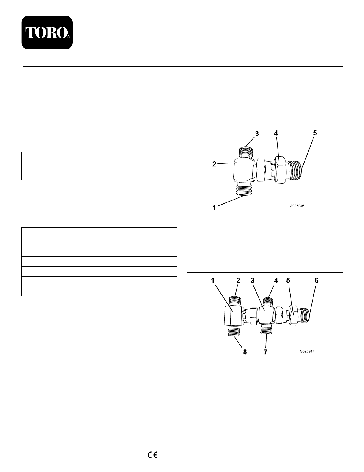
2.AssemblethefrontteeassembliesasshowninFigure1
orFigure2.
Figure1
TM5490
1.Tothefront,leftcutting
unit
2.1/4-inchtee5.Tothe3/8-inchhose
3.Tothefront,rightcutting
unit
4.1/4-inchto3/8-inch
adaptor
Figure2
TM7490
1.1/4-inchswiveltee5.1/4-inchto3/8-inch
©2015—TheToro®Company
8111LyndaleAvenueSouth
Bloomington,MN55420
Registeratwww.T oro.com.
2.Tothefront,rightcutting
unit
3.1/4-inchcrossadaptor7.Totheleft,centercutting
4.Totheright,centercutting
unit
OriginalInstructions(EN)
PrintedintheUK
AllRightsReserved
adaptor
6.Tothe3/8-inchhose
unit
8.Tothefront,leftcutting
unit
*3394-515*A
3.Removethereturnltercaptoletairinandthen
1
2
G028949
3
1
2
3
4
5
6
7
looselyattachit.
4.Notethelocationofthefront-motordrainhoses
attachedtothemanifoldandremovethem.
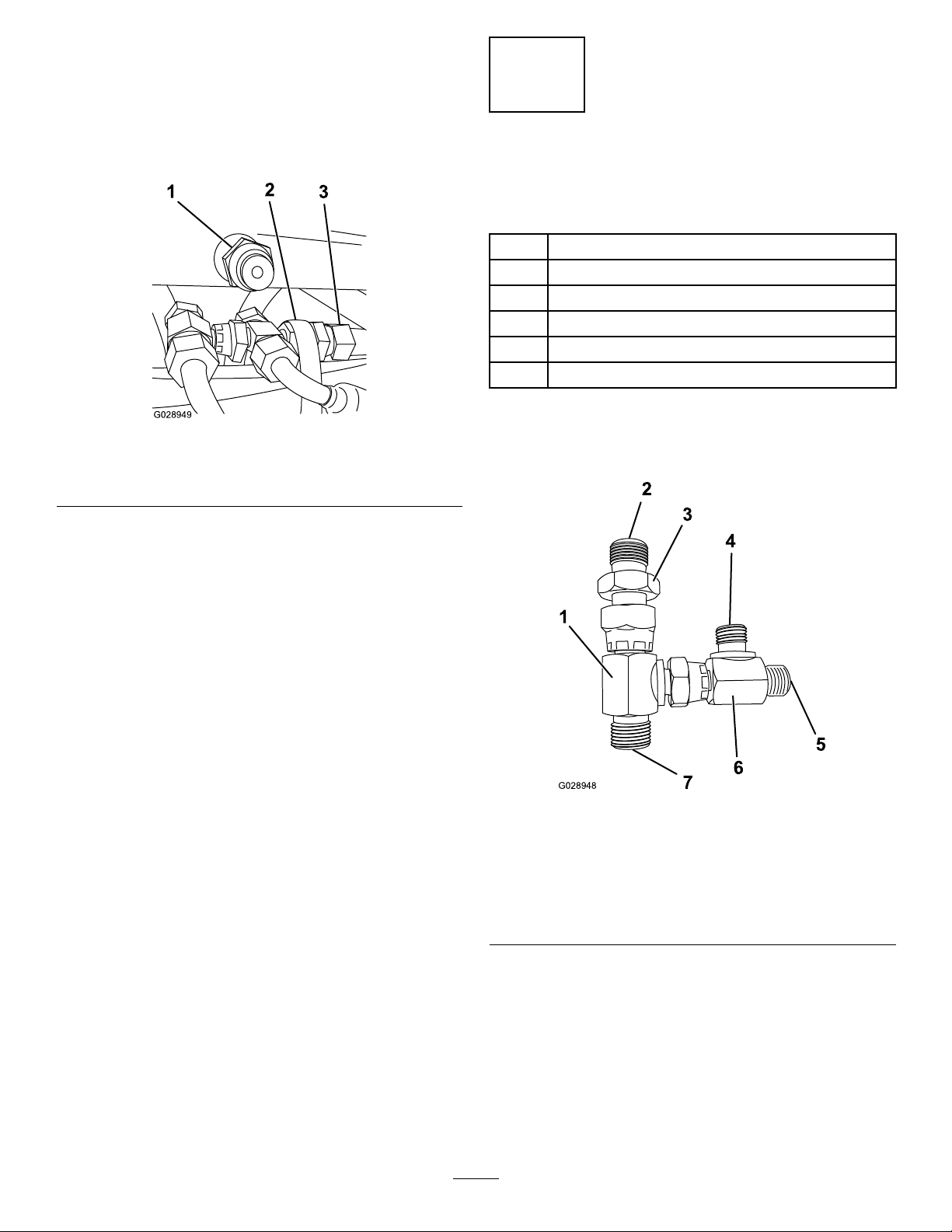
5.Insertblankingcapsintotheholesinthemanifold
(Figure3).
Figure3
1.Blankingcap
2.Cabletie
6.Attachthe3/8-inchhosetothefrontteeassembly.
3.3/8-inchhose
2
InstallingtheRearTee
Assembly
Partsneededforthisprocedure:
1
3/8-inchto1/4-inchswiveltee
1
3/8-inchadaptor
1
1/4-inchswiveltee
2Blankingcaps
1
1/4-inchhose
1
3/8-inchhose
Procedure
1.Assembletherearteeassembly(Figure4).
7.Routethehoseundertheoiltank,layitontopofthe
existinghosebundle,andfeeditoutoftherearofthe
machine.
8.Attachthehosesremovedinstep4tothefronttee
assemblyinthesamelocationstheywerearrangedon
themanifold(Figure1orFigure2).
9.Securethefrontteeassemblytothehosebundlebelow
itwithacabletie(Figure3).
10.Tightenallofthettings.
Figure4
1.3/8-inchto1/4-inchswivel
tee
2.Totheoiltank
3.3/8-inchadaptor7.Tothefronttee
4.Tothecenter,backcutting
unit
2.Removetherearcover.
3.Removethe2motordrainhosesfromtherear
manifold.
5.Totherear,rightcutting
unit
6.1/4-inchswiveltee
4.Insertblankingcapsintotheholesinthemanifold
(Figure5).
2
 Loading...