

Page 1
BladeKit
Model02601/02605HoverPro450/550Machine
ModelNo.111-6800
ModelNo.111-6801
Installation
LooseParts
Usethechartbelowtoverifythatallpartshavebeenshipped.
FormNo.3395-693RevA
InstallationInstructions
ProcedureDescription
Upstopbracket1
1
2
Important:ThiskitisintendedforuseonHoverPro
models02601and02605only.
Insert(M4)
Screw(M4)
Bladebolt1
Blade1
1
InstallingtheUp-StopBracket
Partsneededforthisprocedure:
1Upstopbracket
2
Insert(M4)
2
Screw(M4)
Qty.
Use
2
2
Installtheupstopbracket.
Installtheblade.
Procedure
1.TurnthefuelswitchtotheOffposition.
2.Disconnectthewirefromthesparkplug
3.Tiltthemachineonitsleftsidetogainaccessunder
thedeck.
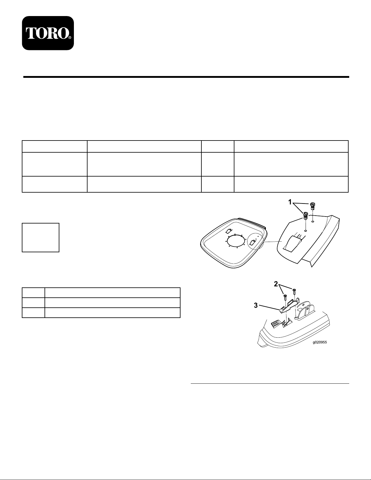
4.Gentlytaptheinserts(M4)intothe2holesinthedeck
asshowninFigure1.
©2015—TheT oro®Company
8111LyndaleAvenueSouth
Bloomington,MN55420
Registeratwww.T oro.com.
Figure1
1.Inserts(M4)
2.Screws(M4)
5.Positiontheup-stopbracketonthetopofthedeckas
showninFigure1andsecureitinplacewith2screws
(M4).
OriginalInstructions(EN)
PrintedintheUK.
AllRightsReserved
3.Upstopbracket
*3395-693*A
Page 2
2
InstallingtheBlade
Partsneededforthisprocedure:
1Bladebolt
1Blade
Procedure
WARNING
Thebladeissharp;contactingthebladecanresult
inseriouspersonalinjury.
•Disconnectthewirefromthesparkplug .
•Weargloveswhenhandlingtheblade.
1.Removethebolt,retainingbolt,andspacerstogain
accesstothebladecarrierassembly .
2.Retainthespacers,anddiscardthebladecarrier
assemblyandthebolt.
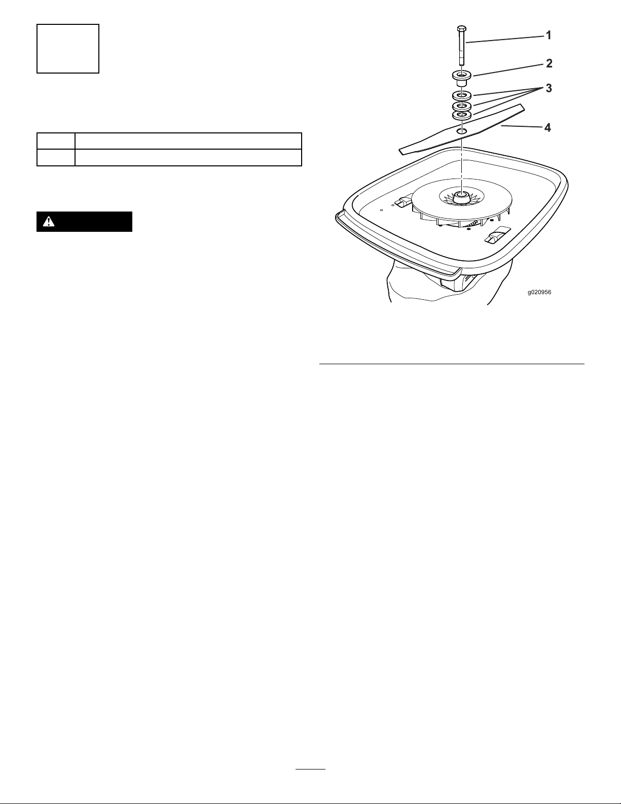
3.Installthebladeusingthesuppliedbladeboltandthe
retainedspacersandretainingboltasshowninFigure
2.RefertotheOperator’sManualforheightadjustment
procedure.
Important:Positionthecurvedendsoftheblade
topointawayfromthemachinesothewords
“GrassSide”areonthebottomofthebladewhen
cutting.
Figure2
1.Bladebolt3.Existingspacers
2.Existingretainingbolt4.Blade
4.Tightenthebladeboltto25N-m(18ft-lb).
2
 Loading...